2003 DODGE RAM engine
[x] Cancel search: enginePage 356 of 2895
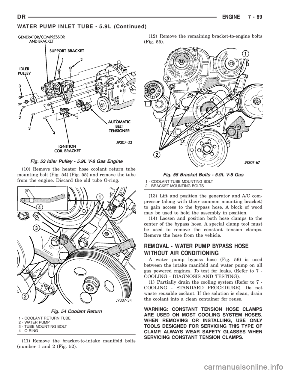
(10) Remove the heater hose coolant return tube
mounting bolt (Fig. 54) (Fig. 55) and remove the tube
from the engine. Discard the old tube O-ring.
(11) Remove the bracket-to-intake manifold bolts
(number 1 and 2 (Fig. 52).(12) Remove the remaining bracket-to-engine bolts
(Fig. 55).
(13) Lift and position the generator and A/C com-
pressor (along with their common mounting bracket)
to gain access to the bypass hose. A block of wood
may be used to hold the assembly in position.
(14) Loosen and position both hose clamps to the
center of the bypass hose. A special clamp tool must
be used to remove the constant tension clamps.
Remove the hose from the vehicle.
REMOVAL - WATER PUMP BYPASS HOSE
WITHOUT AIR CONDITIONING
A water pump bypass hose (Fig. 56) is used
between the intake manifold and water pump on all
gas powered engines. To test for leaks, (Refer to 7 -
COOLING - DIAGNOSIS AND TESTING).
(1) Partially drain the cooling system (Refer to 7 -
COOLING - STANDARD PROCEDURE). Do not
waste reusable coolant. If the solution is clean, drain
the coolant into a clean container for reuse.
WARNING: CONSTANT TENSION HOSE CLAMPS
ARE USED ON MOST COOLING SYSTEM HOSES.
WHEN REMOVING OR INSTALLING, USE ONLY
TOOLS DESIGNED FOR SERVICING THIS TYPE OF
CLAMP. ALWAYS WEAR SAFETY GLASSES WHEN
SERVICING CONSTANT TENSION CLAMPS.
Fig. 53 Idler Pulley - 5.9L V-8 Gas Engine
Fig. 54 Coolant Return
1 - COOLANT RETURN TUBE
2 - WATER PUMP
3 - TUBE MOUNTING BOLT
4 - O-RING
Fig. 55 Bracket Bolts - 5.9L V-8 Gas
1 - COOLANT TUBE MOUNTING BOLT
2 - BRACKET MOUNTING BOLTS
DRENGINE 7 - 69
WATER PUMP INLET TUBE - 5.9L (Continued)
Page 357 of 2895

CAUTION: A number or letter is stamped into the
tongue of the constant tension clamps. If replace-
ment is necessary, use only an original equipment
clamp with a matching number or letter and width.
(2) Loosen both of the bypass hose clamps and
position them to the center of the hose.
(3) Removethe hose from the vehicle.
INSTALLATION
INSTALLATION - WATER PUMP BYPASS HOSE
WITH AIR CONDITIONING
(1) Position the bypass hose clamps to the center
of the bypass hose.
(2) Install the bypass hose to the engine.
(3) Secure both of the hose clamps.
(4) Install the generator-A/C mounting bracket
assembly to the engine. Tighten bolt number 1 (Fig.
53) to 41 N´m (30 ft. lbs.). Tighten bolt number 2
(Fig. 53) to 28 N´m (20 ft. lbs.). Tighten bracket
mounting bolts (Fig. 53) (Fig. 53) to 40 N´m (30 ft.
lbs.).
(5) Install a new O-ring to the heater hose coolant
return tube. Coat the new O-ring with antifreeze
before installation.
(6) Install the coolant return tube and its mount-
ing bolt to the engine.
(7) Connect the throttle body control cables.
(8) Install the oil dipstick mounting bolt.
(9) Install the idler pulley. Tighten the bolt to 41
N´m (30 ft. lbs.) (Fig. 57).
(10) Install the drive belt (Refer to 7 - COOLING/
ACCESSORY DRIVE/DRIVE BELTS - INSTALLA-
TION).CAUTION: When installing the serpentine accessory
drive belt, the belt must be routed correctly. If not,
the engine may overheat due to the water pump
rotating in the wrong direction (Refer to 7 - COOL-
ING/ACCESSORY DRIVE/DRIVE BELTS - INSTALLA-
TION). The correct belt with the correct length must
be used.
(11) Install the air cleaner assembly.
(12) Install the upper radiator hose to the radiator.
(13) Connect the throttle cable to the clip at the
radiator fan shroud.
(14) Connect the wiring harness to the A/C com-
pressor.
(15) Fill the cooling system (Refer to 7 - COOLING
- STANDARD PROCEDURE).
(16) Start and warm the engine. Check for leaks.
INSTALLATION - WATER PUMP BYPASS HOSE
WITHOUT AIR CONDITIONING
(1) Position the bypass hose clamps to the center
of the bypass hose.
(2) Install the bypass hose tothe engine.
(3) Secure both of the hose clamps.
(4) Fill the cooling system (Refer to 7 - COOLING
- STANDARD PROCEDURE).
(5) Start and warm the engine. Check for leaks.
WATER PUMP - 5.7L
REMOVAL
(1) Disconnect negative battery cable.
(2) Drain coolant.
(3) Remove serpentine belt.
(4) Remove fan clutch assembly.
(5) Remove coolant fill bottle.
Fig. 56 Water Pump Bypass Hose - Typical
1 - WATER PUMP BYPASS HOSE
2 - FAN BLADE ASSEMBLY
3 - VISCOUS FAN DRIVE
4 - WATER PUMP AND PULLEY
Fig. 57 Tensioner Mounting
1 - DOWEL PIN HOLE
2 - TENSIONER MOUNTING BRACKET
7 - 70 ENGINEDR
WATER PUMP INLET TUBE - 5.9L (Continued)
Page 358 of 2895
(6) Disconnect washer bottle wiring and hose.
(7) Remove fan shroud assembly.
(8) Remove A/C compressor and genterator brace.
(9) Remove idler pulleys.
(10) Remove belt tensioner assembly.
(11) Remove upper and lower radiator hoses.
(12) Remove heater hoses.
(13) Remove water pump mounting bolts and
remove pump.INSTALLATION
(1) Install water pump and mounting bolts.
Tighten moubting bolts to 24 N´m (18 ft. lbs.).
(2) Install heater hoses.
(3) Install upper and lower radiator hoses.
(4) Install belt tensioner assembly.
(5) Install idler pulleys.
(6) Install A/C compressor and alternator brace.
Tighten bolt and nuts to 28 N´m (21 ft. lbs.).
(7) Install fan shroud assembly.
(8) Connect washer bottle wiring and hose.
(9) Install coolant fill bottle.
(10) Install fan clutch assembly.
(11) Install serpentine belt.
(12) Connect negative battery cable.
(13) Fill coolant.
(14) Pressure test coolant system
DRENGINE 7 - 71
WATER PUMP - 5.7L (Continued)
Page 359 of 2895
TRANSMISSION
TABLE OF CONTENTS
page page
TRANS COOLER
DESCRIPTION
DESCRIPTION........................72
DESCRIPTION........................72
OPERATION...........................72
REMOVAL.............................72
DISASSEMBLY - 5.9L ONLY...............73
ASSEMBLY - 5.9L ONLY..................73
INSTALLATION.........................73TRANS COOLER - 5.9L DIESEL
DESCRIPTION.........................73
OPERATION...........................74
REMOVAL
REMOVALÐAIR TO OIL COOLER.........74
REMOVALÐWATER TO OIL COOLER......74
INSTALLATION
INSTALLATIONÐAIR TO OIL COOLER.....75
INSTALLATION.......................75
TRANS COOLER
DESCRIPTION
DESCRIPTION
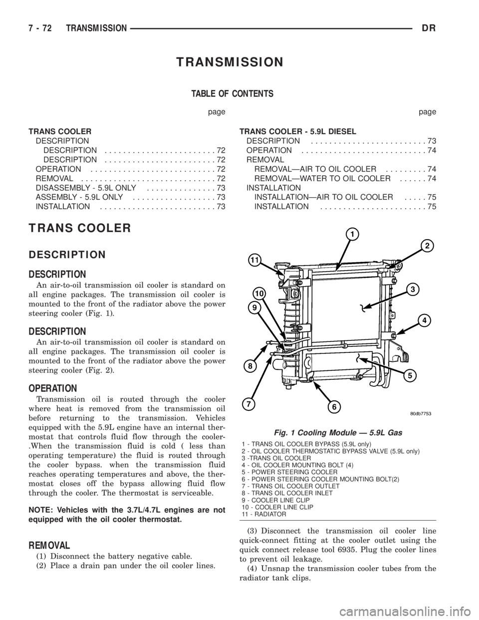
An air-to-oil transmission oil cooler is standard on
all engine packages. The transmission oil cooler is
mounted to the front of the radiator above the power
steering cooler (Fig. 1).
DESCRIPTION
An air-to-oil transmission oil cooler is standard on
all engine packages. The transmission oil cooler is
mounted to the front of the radiator above the power
steering cooler (Fig. 2).
OPERATION
Transmission oil is routed through the cooler
where heat is removed from the transmission oil
before returning to the transmission. Vehicles
equipped with the 5.9L engine have an internal ther-
mostat that controls fluid flow through the cooler-
.When the transmission fluid is cold ( less than
operating temperature) the fluid is routed through
the cooler bypass. when the transmission fluid
reaches operating temperatures and above, the ther-
mostat closes off the bypass allowing fluid flow
through the cooler. The thermostat is serviceable.
NOTE: Vehicles with the 3.7L/4.7L engines are not
equipped with the oil cooler thermostat.
REMOVAL
(1) Disconnect the battery negative cable.
(2) Place a drain pan under the oil cooler lines.(3) Disconnect the transmission oil cooler line
quick-connect fitting at the cooler outlet using the
quick connect release tool 6935. Plug the cooler lines
to prevent oil leakage.
(4) Unsnap the transmission cooler tubes from the
radiator tank clips.
Fig. 1 Cooling Module Ð 5.9L Gas
1 - TRANS OIL COOLER BYPASS (5.9L only)
2 - OIL COOLER THERMOSTATIC BYPASS VALVE (5.9L only)
3 -TRANS OIL COOLER
4 - OIL COOLER MOUNTING BOLT (4)
5 - POWER STEERING COOLER
6 - POWER STEERING COOLER MOUNTING BOLT(2)
7 - TRANS OIL COOLER OUTLET
8 - TRANS OIL COOLER INLET
9 - COOLER LINE CLIP
10 - COOLER LINE CLIP
11 - RADIATOR
7 - 72 TRANSMISSIONDR
Page 360 of 2895
(5) Remove the bolts attaching the transmission
cooler to the radiator.
(6) Remove oil cooler from the vehicle. Take care
not to damage the radiator core or transmission
cooler tubes.
DISASSEMBLY - 5.9L ONLY
NOTE: The transmission oil cooler uses an internal
thermostat to control transmission oil flow through
the cooler. This thermostat is servicable.
(1) Remove the transmission oil cooler (Refer to 7 -
COOLING/TRANSMISSION/TRANS COOLER -
REMOVAL).
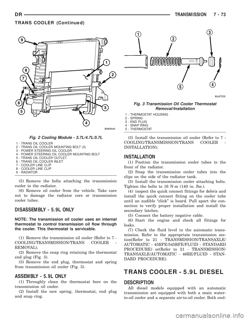
(2) Remove the snap ring retaining the thermostat
end plug (Fig. 3).
(3) Remove the end plug, thermostat and spring
from transmission oil cooler (Fig. 3).
ASSEMBLY - 5.9L ONLY
(1) Throughly clean the thermostat bore on the
transmission oil cooler.
(2) Install the new spring, thermostat, end plug
and snap ring.(3) Install the transmission oil cooler (Refer to 7 -
COOLING/TRANSMISSION/TRANS COOLER -
INSTALLATION).
INSTALLATION
(1) Position the transmission cooler tubes to the
front of the radiator.
(2) Snap the transmission cooler tubes into the
clips on the side of the radiator tank.
(3) Install the transmission cooler attaching bolts.
Tighten the bolts to 16 N´m (140 in. lbs.).
(4) inspect the quick connect fittings for debris and
install the quick connect fitting on the cooler tube
until an audible ªclickº is heard. Pull apart the con-
nection to verify proper installation and install the
secondary latches.
(5) Connect the battery negative cable.
(6) Start the engine and check all fittings for
leaks.
(7) Check the fluid level in the automatic trans-
mission. Refer to the appropriate transmission sec-
tion(Refer to 21 - TRANSMISSION/TRANSAXLE/
AUTOMATIC - 45RFE/545RFE/FLUID - STANDARD
PROCEDURE) or(Refer to 21 - TRANSMISSION/
TRANSAXLE/AUTOMATIC - 46RE/FLUID - STAN-
DARD PROCEDURE).
TRANS COOLER - 5.9L DIESEL
DESCRIPTION
All diesel models equipped with an automatic
transmission are equipped with both a main water-
to-oil cooler and a separate air-to-oil cooler. Both cool-
Fig. 2 Cooling Module - 3.7L/4.7L/5.7L
1 - TRANS OIL COOLER
2 - TRANS OIL COOLER MOUNTING BOLT (3)
3 - POWER STEERING OIL COOLER
4 - POWER STEERING OIL COOLER MOUNTING BOLT
5 - TRANS OIL COOLER OUTLET
6 - TRANS OIL COOLER INLET
7 - COOLER LINE CLIP
8 - COOLER LINE CLIP
9 - RADIATOR
Fig. 3 Transmission Oil Cooler Thermostat
Removal/Installation
1 - THERMOSTAT HOUSING
2 - SPRING
3 - END PLUG
4 - SNAP RING
5 - THERMOSTAT
DRTRANSMISSION 7 - 73
TRANS COOLER (Continued)
Page 361 of 2895
ers are supplied as standard equipment on diesel
engine powered models when equipped with an auto-
matic transmission.
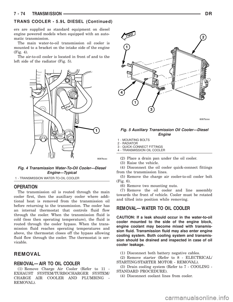
The main water-to-oil transmission oil cooler is
mounted to a bracket on the intake side of the engine
(Fig. 4).
The air-to-oil cooler is located in front of and to the
left side of the radiator (Fig. 5).
OPERATION
The transmission oil is routed through the main
cooler first, then the auxiliary cooler where addi-
tional heat is removed from the transmission oil
before returning to the transmission. The cooler has
an internal thermostat that controls fluid flow
through the cooler. When the transmission fluid is
cold (less then operating temperature), the fluid is
routed through the cooler bypass. When the trans-
mission fluid reaches operating temperatures and
above, the thermostat closes off the bypass allowing
fluid flow through the cooler. The thermostat is ser-
vicable.
REMOVAL
REMOVALÐAIR TO OIL COOLER
(1) Remove Charge Air Cooler (Refer to 11 -
EXHAUST SYSTEM/TURBOCHARGER SYSTEM/
CHARGE AIR COOLER AND PLUMBING -
REMOVAL).(2) Place a drain pan under the oil cooler.
(3) Raise the vehicle.
(4) Disconnect the oil cooler quick-connect fittings
from the transmission lines.
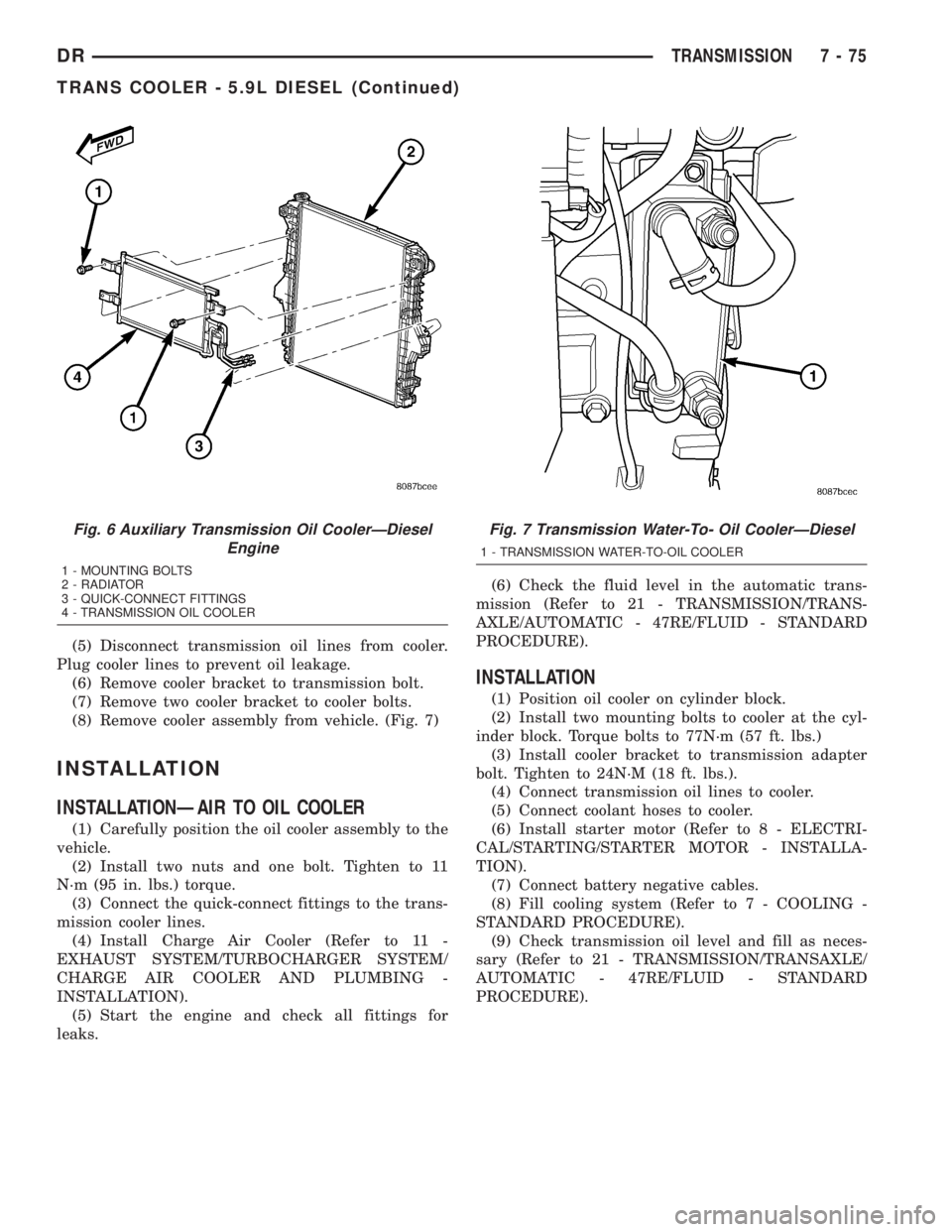
(5) Remove the charge air cooler-to-oil cooler bolt
(Fig. 6).
(6) Remove two mounting nuts.
(7) Remove the oil cooler and line assembly
towards the front of vehicle. Cooler must be rotated
and tilted into position while removing.
REMOVALÐWATER TO OIL COOLER
CAUTION: If a leak should occur in the water-to-oil
cooler mounted to the side of the engine block,
engine coolant may become mixed with transmis-
sion fluid. Transmission fluid may also enter engine
cooling system. Both cooling system and transmis-
sion should be drained and inspected in case of oil
cooler leakage.
(1) Disconnect both battery negative cables.
(2) Remove starter (Refer to 8 - ELECTRICAL/
STARTING/STARTER MOTOR - REMOVAL).
(3) Drain cooling system (Refer to 7 - COOLING -
STANDARD PROCEDURE).
(4) Disconnect coolant lines from cooler.
Fig. 4 Transmission Water-To-Oil CoolerÐDiesel
EngineÐTypical
1 - TRANSMISSION WATER-TO-OIL COOLER
Fig. 5 Auxiliary Transmission Oil CoolerÐDiesel
Engine
1 - MOUNTING BOLTS
2 - RADIATOR
3 - QUICK-CONNECT FITTINGS
4 - TRANSMISSION OIL COOLER
7 - 74 TRANSMISSIONDR
TRANS COOLER - 5.9L DIESEL (Continued)
Page 362 of 2895
(5) Disconnect transmission oil lines from cooler.
Plug cooler lines to prevent oil leakage.
(6) Remove cooler bracket to transmission bolt.
(7) Remove two cooler bracket to cooler bolts.
(8) Remove cooler assembly from vehicle. (Fig. 7)
INSTALLATION
INSTALLATIONÐAIR TO OIL COOLER
(1) Carefully position the oil cooler assembly to the
vehicle.
(2) Install two nuts and one bolt. Tighten to 11
N´m (95 in. lbs.) torque.
(3) Connect the quick-connect fittings to the trans-
mission cooler lines.
(4) Install Charge Air Cooler (Refer to 11 -
EXHAUST SYSTEM/TURBOCHARGER SYSTEM/
CHARGE AIR COOLER AND PLUMBING -
INSTALLATION).
(5) Start the engine and check all fittings for
leaks.(6) Check the fluid level in the automatic trans-
mission (Refer to 21 - TRANSMISSION/TRANS-
AXLE/AUTOMATIC - 47RE/FLUID - STANDARD
PROCEDURE).
INSTALLATION
(1) Position oil cooler on cylinder block.
(2) Install two mounting bolts to cooler at the cyl-
inder block. Torque bolts to 77N´m (57 ft. lbs.)
(3) Install cooler bracket to transmission adapter
bolt. Tighten to 24N´M (18 ft. lbs.).
(4) Connect transmission oil lines to cooler.
(5) Connect coolant hoses to cooler.
(6) Install starter motor (Refer to 8 - ELECTRI-
CAL/STARTING/STARTER MOTOR - INSTALLA-
TION).
(7) Connect battery negative cables.
(8) Fill cooling system (Refer to 7 - COOLING -
STANDARD PROCEDURE).
(9) Check transmission oil level and fill as neces-
sary (Refer to 21 - TRANSMISSION/TRANSAXLE/
AUTOMATIC - 47RE/FLUID - STANDARD
PROCEDURE).
Fig. 6 Auxiliary Transmission Oil CoolerÐDiesel
Engine
1 - MOUNTING BOLTS
2 - RADIATOR
3 - QUICK-CONNECT FITTINGS
4 - TRANSMISSION OIL COOLER
Fig. 7 Transmission Water-To- Oil CoolerÐDiesel
1 - TRANSMISSION WATER-TO-OIL COOLER
DRTRANSMISSION 7 - 75
TRANS COOLER - 5.9L DIESEL (Continued)
Page 368 of 2895
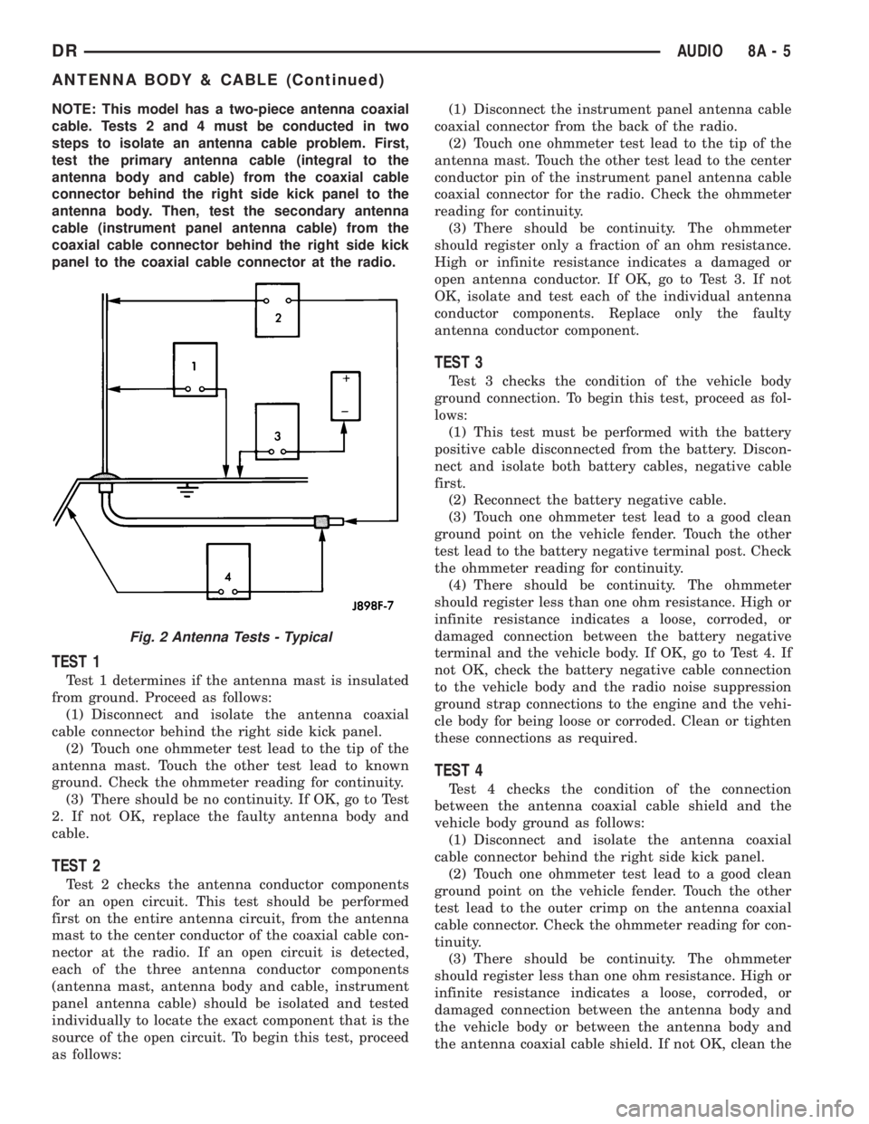
NOTE: This model has a two-piece antenna coaxial
cable. Tests 2 and 4 must be conducted in two
steps to isolate an antenna cable problem. First,
test the primary antenna cable (integral to the
antenna body and cable) from the coaxial cable
connector behind the right side kick panel to the
antenna body. Then, test the secondary antenna
cable (instrument panel antenna cable) from the
coaxial cable connector behind the right side kick
panel to the coaxial cable connector at the radio.
TEST 1
Test 1 determines if the antenna mast is insulated
from ground. Proceed as follows:
(1) Disconnect and isolate the antenna coaxial
cable connector behind the right side kick panel.
(2) Touch one ohmmeter test lead to the tip of the
antenna mast. Touch the other test lead to known
ground. Check the ohmmeter reading for continuity.
(3) There should be no continuity. If OK, go to Test
2. If not OK, replace the faulty antenna body and
cable.
TEST 2
Test 2 checks the antenna conductor components
for an open circuit. This test should be performed
first on the entire antenna circuit, from the antenna
mast to the center conductor of the coaxial cable con-
nector at the radio. If an open circuit is detected,
each of the three antenna conductor components
(antenna mast, antenna body and cable, instrument
panel antenna cable) should be isolated and tested
individually to locate the exact component that is the
source of the open circuit. To begin this test, proceed
as follows:(1) Disconnect the instrument panel antenna cable
coaxial connector from the back of the radio.
(2) Touch one ohmmeter test lead to the tip of the
antenna mast. Touch the other test lead to the center
conductor pin of the instrument panel antenna cable
coaxial connector for the radio. Check the ohmmeter
reading for continuity.
(3) There should be continuity. The ohmmeter
should register only a fraction of an ohm resistance.
High or infinite resistance indicates a damaged or
open antenna conductor. If OK, go to Test 3. If not
OK, isolate and test each of the individual antenna
conductor components. Replace only the faulty
antenna conductor component.
TEST 3
Test 3 checks the condition of the vehicle body
ground connection. To begin this test, proceed as fol-
lows:
(1) This test must be performed with the battery
positive cable disconnected from the battery. Discon-
nect and isolate both battery cables, negative cable
first.
(2) Reconnect the battery negative cable.
(3) Touch one ohmmeter test lead to a good clean
ground point on the vehicle fender. Touch the other
test lead to the battery negative terminal post. Check
the ohmmeter reading for continuity.
(4) There should be continuity. The ohmmeter
should register less than one ohm resistance. High or
infinite resistance indicates a loose, corroded, or
damaged connection between the battery negative
terminal and the vehicle body. If OK, go to Test 4. If
not OK, check the battery negative cable connection
to the vehicle body and the radio noise suppression
ground strap connections to the engine and the vehi-
cle body for being loose or corroded. Clean or tighten
these connections as required.
TEST 4
Test 4 checks the condition of the connection
between the antenna coaxial cable shield and the
vehicle body ground as follows:
(1) Disconnect and isolate the antenna coaxial
cable connector behind the right side kick panel.
(2) Touch one ohmmeter test lead to a good clean
ground point on the vehicle fender. Touch the other
test lead to the outer crimp on the antenna coaxial
cable connector. Check the ohmmeter reading for con-
tinuity.
(3) There should be continuity. The ohmmeter
should register less than one ohm resistance. High or
infinite resistance indicates a loose, corroded, or
damaged connection between the antenna body and
the vehicle body or between the antenna body and
the antenna coaxial cable shield. If not OK, clean the
Fig. 2 Antenna Tests - Typical
DRAUDIO 8A - 5
ANTENNA BODY & CABLE (Continued)