2003 DODGE RAM engine
[x] Cancel search: enginePage 2788 of 2895
NOTE: The air gap is determined by the spacer
shims. When installing an original, or a new clutch
assembly, try the original shims first. When install-
ing a new clutch onto a compressor that previously
did not have a clutch, use a 1.0, 0.50, and 0.13 mil-
limeter (0.040, 0.020, and 0.005 inch) shims from the
new clutch hardware package that is provided with
the new clutch.
(9) To complete the procedure, (Refer to 24 -
HEATING & AIR CONDITIONING/PLUMBING/A/C
COMPRESSOR - INSTALLATION).
A/C COMPRESSOR CLUTCH
RELAY
DESCRIPTION
The compressor clutch relay is a International
Standards Organization (ISO) micro-relay. The termi-
nal designations and functions are the same as a con-
ventional ISO relay. However, the micro-relay
terminal orientation (footprint) is different, the cur-
rent capacity is lower, and the relay case dimensions
are smaller than those of the conventional ISO relay.
The compressor clutch relay is located in the Power
Distribution Center (PDC) in the engine compart-
ment. Refer to the PDC label for relay identification
and location.
OPERATION
The compressor clutch relay is a electromechanical
device that switches battery current to the compres-
sor clutch coil when the Powertrain Control Module
(PCM) grounds the coil side of the relay. The PCM
responds to inputs from the A/C Heater mode control
switch, the A/C low pressure switch, and the A/C
high pressure switch. (Refer to 24 - HEATING & AIR
CONDITIONING/CONTROLS/A/C COMPRESSOR
CLUTCH RELAY - DIAGNOSIS AND TESTING)
The compressor clutch relay cannot be repaired
and, if faulty or damaged, it must be replaced.
DIAGNOSIS AND TESTING - COMPRESSOR
CLUTCH RELAY
RELAY TEST
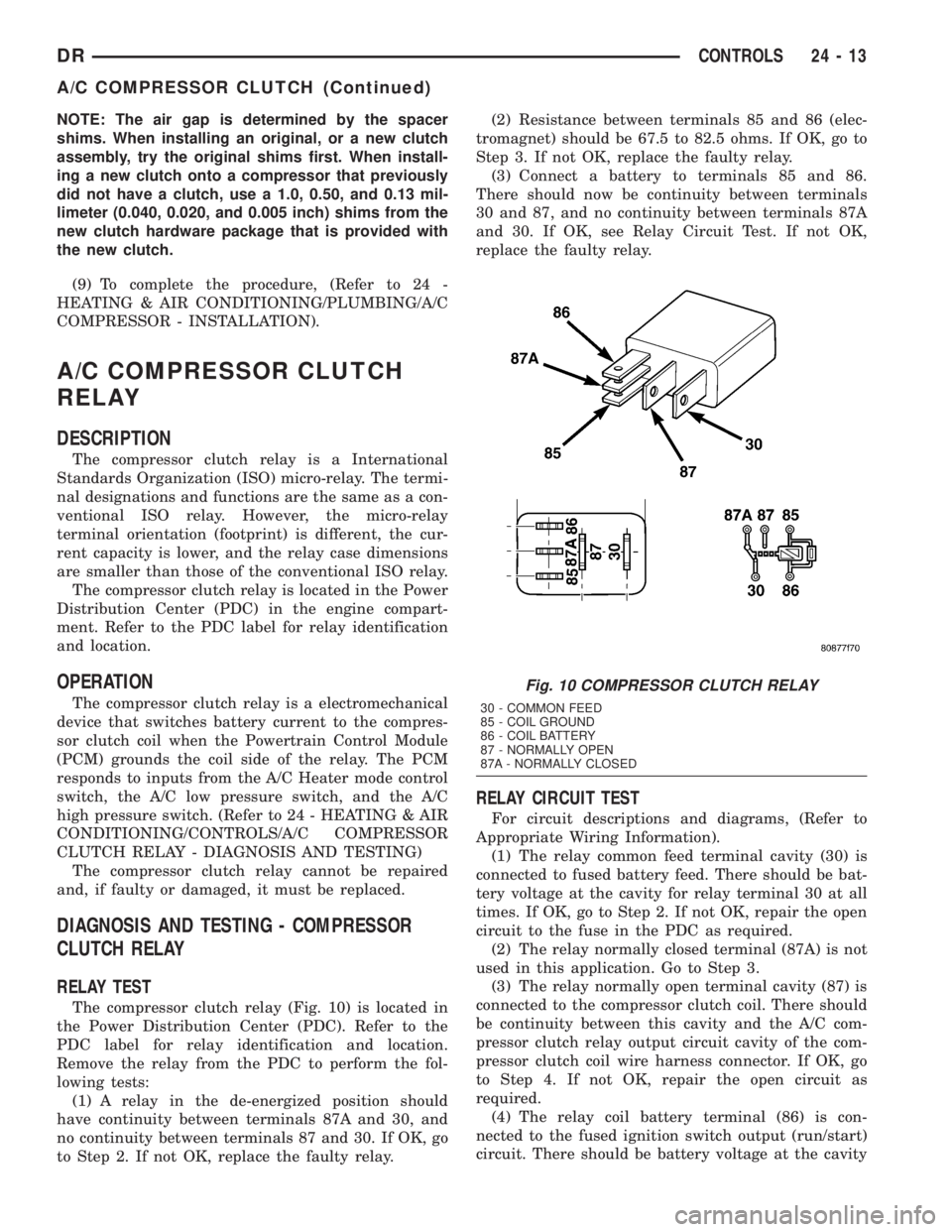
The compressor clutch relay (Fig. 10) is located in
the Power Distribution Center (PDC). Refer to the
PDC label for relay identification and location.
Remove the relay from the PDC to perform the fol-
lowing tests:
(1) A relay in the de-energized position should
have continuity between terminals 87A and 30, and
no continuity between terminals 87 and 30. If OK, go
to Step 2. If not OK, replace the faulty relay.(2) Resistance between terminals 85 and 86 (elec-
tromagnet) should be 67.5 to 82.5 ohms. If OK, go to
Step 3. If not OK, replace the faulty relay.
(3) Connect a battery to terminals 85 and 86.
There should now be continuity between terminals
30 and 87, and no continuity between terminals 87A
and 30. If OK, see Relay Circuit Test. If not OK,
replace the faulty relay.
RELAY CIRCUIT TEST
For circuit descriptions and diagrams, (Refer to
Appropriate Wiring Information).
(1) The relay common feed terminal cavity (30) is
connected to fused battery feed. There should be bat-
tery voltage at the cavity for relay terminal 30 at all
times. If OK, go to Step 2. If not OK, repair the open
circuit to the fuse in the PDC as required.
(2) The relay normally closed terminal (87A) is not
used in this application. Go to Step 3.
(3) The relay normally open terminal cavity (87) is
connected to the compressor clutch coil. There should
be continuity between this cavity and the A/C com-
pressor clutch relay output circuit cavity of the com-
pressor clutch coil wire harness connector. If OK, go
to Step 4. If not OK, repair the open circuit as
required.
(4) The relay coil battery terminal (86) is con-
nected to the fused ignition switch output (run/start)
circuit. There should be battery voltage at the cavity
Fig. 10 COMPRESSOR CLUTCH RELAY
30 - COMMON FEED
85 - COIL GROUND
86 - COIL BATTERY
87 - NORMALLY OPEN
87A - NORMALLY CLOSED
DRCONTROLS 24 - 13
A/C COMPRESSOR CLUTCH (Continued)
Page 2790 of 2895
INSTALLATION
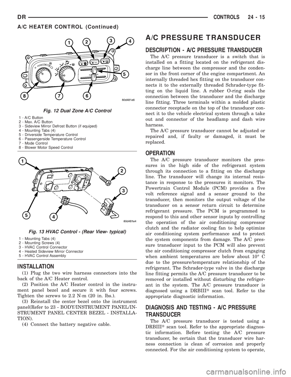
(1) Plug the two wire harness connectors into the
back of the A/C Heater control.
(2) Position the A/C Heater control in the instru-
ment panel bezel and secure it with four screws.
Tighten the screws to 2.2 N´m (20 in. lbs.).
(3) Reinstall the center bezel onto the instrument
panel(Refer to 23 - BODY/INSTRUMENT PANEL/IN-
STRUMENT PANEL CENTER BEZEL - INSTALLA-
TION).
(4) Connect the battery negative cable.
A/C PRESSURE TRANSDUCER
DESCRIPTION - A/C PRESSURE TRANSDUCER
The A/C pressure transducer is a switch that is
installed on a fitting located on the refrigerant dis-
charge line between the compressor and the conden-
sor in the front corner of the engine compartment. An
internally threaded hex fitting on the transducer con-
nects it to the externally threaded Schrader-type fit-
ting on the liquid line. A rubber O-ring seals the
connection between the transducer and the discharge
line fitting. Three terminals within a molded plastic
connector receptacle on the top of the transducer con-
nect it to the vehicle electrical system through a take
out and connector of the headlamp and dash wire
harness.
The A/C pressure transducer cannot be adjusted or
repaired and, if faulty or damaged, it must be
replaced.
OPERATION
The A/C pressure transducer monitors the pres-
sures in the high side of the refrigerant system
through its connection to a fitting on the discharge
line. The transducer will change its internal resis-
tance in response to the pressures it monitors. The
Powertrain Control Module (PCM) provides a five
volt reference signal and a sensor ground to the
transducer, then monitors the output voltage of the
transducer on a sensor return circuit to determine
refrigerant pressure. The PCM is programmed to
respond to this and other sensor inputs by controlling
the operation of the air conditioning compressor
clutch and the radiator cooling fan to help optimize
air conditioning system performance and to protect
the system components from damage. The A/C pres-
sure transducer input to the PCM will also prevent
the air conditioning compressor clutch from engaging
when ambient temperatures are below about 10É C
due to the pressure/temperature relationship of the
refrigerant. The Schrader-type valve in the discharge
line fitting permits the A/C pressure transducer to be
removed or installed without disturbing the refriger-
ant in the system. The A/C pressure transducer is
diagnosed using a DRBIIItscan tool. Refer to the
appropriate diagnostic information.
DIAGNOSIS AND TESTING - A/C PRESSURE
TRANSDUCER
The A/C pressure transducer is tested using a
DRBIIItscan tool. Refer to the appropriate diagnos-
tic information. Before testing the A/C pressure
transducer, be certain that the transducer wire har-
ness connection is clean of corrosion and properly
connected. For the air conditioning system to operate,
Fig. 12 Dual Zone A/C Control
1 - A/C Button
2 - Max. A/C Button
3 - Sideview Mirror Defrost Button (if equiped)
4 - Mounting Tabs (4)
5 - Driverside Temperature Control
6 - Passengerside Temperature Control
7 - Mode Control
8 - Blower Motor Speed Control
Fig. 13 HVAC Control - (Rear View- typical)
1 - Mounting Tabs (4)
2 - Mounting Screws (4)
3 - HVAC Control Connector
4 - Heated Sideview Mirror Connector
5 - HVAC Control Assembly
DRCONTROLS 24 - 15
A/C HEATER CONTROL (Continued)
Page 2803 of 2895
(3) Recover the refrigerant from the refrigerant
system. (Refer to 24 - HEATING & AIR CONDI-
TIONING/PLUMBING - STANDARD PROCEDURE -
REFRIGERANT RECOVERY)
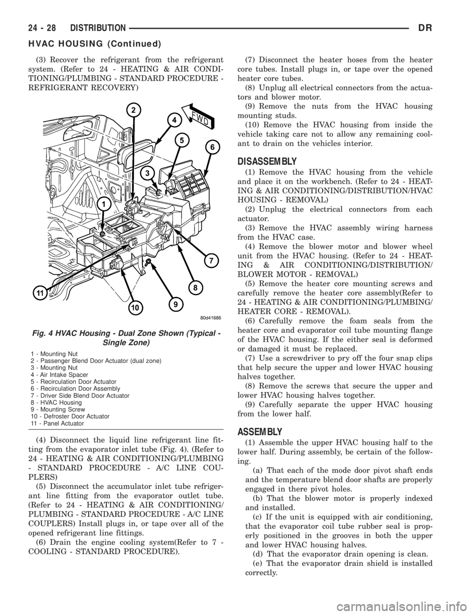
(4) Disconnect the liquid line refrigerant line fit-
ting from the evaporator inlet tube (Fig. 4). (Refer to
24 - HEATING & AIR CONDITIONING/PLUMBING
- STANDARD PROCEDURE - A/C LINE COU-
PLERS)
(5) Disconnect the accumulator inlet tube refriger-
ant line fitting from the evaporator outlet tube.
(Refer to 24 - HEATING & AIR CONDITIONING/
PLUMBING - STANDARD PROCEDURE - A/C LINE
COUPLERS) Install plugs in, or tape over all of the
opened refrigerant line fittings.
(6) Drain the engine cooling system(Refer to 7 -
COOLING - STANDARD PROCEDURE).(7) Disconnect the heater hoses from the heater
core tubes. Install plugs in, or tape over the opened
heater core tubes.
(8) Unplug all electrical connectors from the actua-
tors and blower motor.
(9) Remove the nuts from the HVAC housing
mounting studs.
(10) Remove the HVAC housing from inside the
vehicle taking care not to allow any remaining cool-
ant to drain on the vehicles interior.
DISASSEMBLY
(1) Remove the HVAC housing from the vehicle
and place it on the workbench. (Refer to 24 - HEAT-
ING & AIR CONDITIONING/DISTRIBUTION/HVAC
HOUSING - REMOVAL)
(2) Unplug the electrical connectors from each
actuator.
(3) Remove the HVAC assembly wiring harness
from the HVAC case.
(4) Remove the blower motor and blower wheel
unit from the HVAC housing. (Refer to 24 - HEAT-
ING & AIR CONDITIONING/DISTRIBUTION/
BLOWER MOTOR - REMOVAL)
(5) Remove the heater core mounting screws and
carefully remove the heater core assembly(Refer to
24 - HEATING & AIR CONDITIONING/PLUMBING/
HEATER CORE - REMOVAL).
(6) Carefully remove the foam seals from the
heater core and evaporator coil tube mounting flange
of the HVAC housing. If the either seal is deformed
or damaged it must be replaced.
(7) Use a screwdriver to pry off the four snap clips
that help secure the upper and lower HVAC housing
halves together.
(8) Remove the screws that secure the upper and
lower HVAC housing halves together.
(9) Carefully separate the upper HVAC housing
from the lower half.
ASSEMBLY
(1) Assemble the upper HVAC housing half to the
lower half. During assembly, be certain of the follow-
ing.
(a) That each of the mode door pivot shaft ends
and the temperature blend door shafts are properly
engaged in there pivot holes.
(b) That the blower motor is properly indexed
and installed.
(c) If the unit is equipped with air conditioning,
that the evaporator coil tube rubber seal is prop-
erly positioned in the grooves in both the upper
and lower HVAC housing halves.
(d) That the evaporator drain opening is clean.
(e) That the evaporator drain shield is installed
correctly.
Fig. 4 HVAC Housing - Dual Zone Shown (Typical -
Single Zone)
1 - Mounting Nut
2 - Passenger Blend Door Actuator (dual zone)
3 - Mounting Nut
4 - Air Intake Spacer
5 - Recirculation Door Actuator
6 - Recirculation Door Assembly
7 - Driver Side Blend Door Actuator
8 - HVAC Housing
9 - Mounting Screw
10 - Defroster Door Actuator
11 - Panel Actuator
24 - 28 DISTRIBUTIONDR
HVAC HOUSING (Continued)
Page 2804 of 2895
(2) Install the screws and snap clips that secure
the upper and lower HVAC housing halves to each
other. Tighten the screws to 2.2 N´m (20 in. lbs.).
(3) Install the blower motor and wheel unit in the
HVAC housing. (Refer to 24 - HEATING & AIR CON-
DITIONING/DISTRIBUTION/BLOWER MOTOR -
INSTALLATION)
(4) Install the foam seals on the flanges around
the heater core and evaporator coil tube mounting
flange of the HVAC housing. Repair or replace any
seals as required.
(5) Install the electrical wiring harness for the
acutators. Make sure the wires are routed through
all wiring retainers, replace any retainers that are
damaged or missing.
(6) Connect the wiring harness to each actuator,
making sure each connector is securely attached.
INSTALLATION
WARNING: IF THE VEHICLE IS EQUIPPED WITH AIR
CONDITIONING, REVIEW THE WARNINGS AND
CAUTIONS IN PLUMBING BEFORE PERFORMING
THE FOLLOWING OPERATION. (Refer to 24 - HEAT-
ING & AIR CONDITIONING/PLUMBING - WARNING)
(Refer to 24 - HEATING & AIR CONDITIONING/
PLUMBING - CAUTION) (Refer to 24 - HEATING &
AIR CONDITIONING/PLUMBING - CAUTION -
REFRIGERANT HOSES/LINES/TUBES PRECAU-
TIONS)
(1) Position the HVAC housing to the dash panel.
Be certain that the evaporator condensate drain tube
and the housing mounting studs are inserted into
their correct mounting holes.
(2) Install and tighten the nuts onto the HVAC
housing mounting studs. Tighten the nuts to 6.2 N´m
(55 in.lbs.).
(3) Connect the HVAC system electrical connec-
tors.
(4) Unplug or remove the tape from the heater
core tubes. Connect the heater hoses to the heater
core tubes and fill the engine cooling system(Refer to
7 - COOLING/ENGINE - STANDARD PROCE-
DURE).
(5) Unplug or remove the tape from the liquid line
and the evaporator inlet tube fittings. Connect the
liquid line coupler to the evaporator inlet tube. (Refer
to 24 - HEATING & AIR CONDITIONING/PLUMB-
ING - STANDARD PROCEDURE - A/C LINE COU-
PLERS)(6) Evacuate the refrigerant system. (Refer to 24 -
HEATING & AIR CONDITIONING/PLUMBING -
STANDARD PROCEDURE - REFRIGERANT SYS-
TEM EVACUATE)
(7) Charge the refrigerant system. (Refer to 24 -
HEATING & AIR CONDITIONING/PLUMBING -
STANDARD PROCEDURE - REFRIGERANT SYS-
TEM CHARGE)
(8) Install the instrument panel in the vehicle(Re-
fer to 23 - BODY/INSTRUMENT PANEL - INSTAL-
LATION).
(9) Connect the battery negative cable.
(10) Start the engine and check for proper opera-
tion of the heating and air conditioning systems.
(11) Run the calibration procedure.
INSTRUMENT PANEL DUCTS
REMOVAL
(1) Disconnect and isolate the battery negative
cable.
(2) Remove the HVAC assembly from the vehi-
cle(Refer to 24 - HEATING & AIR CONDITIONING/
DISTRIBUTION/HVAC HOUSING - REMOVAL).
(3) Disasemble the HVAC housing(Refer to 24 -
HEATING & AIR CONDITIONING/DISTRIBUTION/
HVAC HOUSING - DISASSEMBLY).
(4) Remove the panel door actuator from the hous-
ing if not already removed.
(5) With the actuator removed you can take the
door and shift it so that one pivot point will clear the
housing. You can then tilt the door and remove it
from the housing.
INSTALLATION
(1) Take the door and tilt it so one pivot point is
installed. The carfully install the second pivot point.
Check to be sure no binding of the door is occuring,
repair as required.
(2) Reassemble the HVAC housing(Refer to 24 -
HEATING & AIR CONDITIONING/DISTRIBUTION/
HVAC HOUSING - ASSEMBLY).
(3) Install the HVAC assembly into the vehicle(Re-
fer to 24 - HEATING & AIR CONDITIONING/DIS-
TRIBUTION/INSTRUMENT PANEL DUCTS -
INSTALLATION).
(4) Connect the battery negative cable.
DRDISTRIBUTION 24 - 29
HVAC HOUSING (Continued)
Page 2806 of 2895
PLUMBING
TABLE OF CONTENTS
page page
PLUMBING
DESCRIPTION - REFRIGERANT LINE.......32
OPERATION- REFRIGERANT LINES........32
WARNING
SERVICE WARNINGS..................32
CAUTION
SERVICE CAUTIONS..................33
CAUTION - REFRIGERANT HOSES/LINES/
TUBES PRECAUTIONS.................33
STANDARD PROCEDURE
STANDARD PROCEDURE - REFRIGERANT
SYSTEM SERVICE EQUIPMENT..........34
STANDARD PROCEDURE - REFRIGERANT
RECOVERY..........................34
STANDARD PROCEDURE - REFRIGERANT
SYSTEM EVACUATE...................35
STANDARD PROCEDURE - REFRIGERANT
SYSTEM CHARGE.....................35
SPECIFICATIONS - CHARGE CAPACITY.....35
A/C COMPRESSOR
DESCRIPTION
DESCRIPTION........................35
DESCRIPTION - HIGH PRESSURE RELIEF
VALVE..............................35
OPERATION
OPERATION.........................36
OPERATION - HIGH PRESSURE RELIEF
VALVE..............................36
DIAGNOSIS AND TESTING - A/C
COMPRESSOR NOISE.................36
REMOVAL
REMOVAL...........................37
REMOVAL - 5.9L DIESEL ENGINE.........37
INSTALLATION
INSTALLATION.......................38
INSTALLATION - 5.9L DIESEL ENGINE.....39
A/C CONDENSER
DESCRIPTION.........................39
OPERATION...........................39
REMOVAL
REMOVAL - 3.7, 4.7 and 5.7L ENGINES....39
REMOVAL - 5.9L DIESEL ENGINE.........40
REMOVAL - 8.0L Engine................40
INSTALLATION
INSTALLATION - 3.7, 4.7 and 5.7L ENGINES . 41
INSTALLATION - 5.9L DIESEL ENGINE.....42
INSTALLATION - 8.0L Engine.............42A/C CONDENSER FAN
REMOVAL - CONDENSER FAN (GAS ENGINE
ONLY - 3.7, 4.7 & 5.7L).................43
INSTALLATION - CONDENSER FAN (GAS
ENGINE ONLY - 3.7, 4.7 & 5.7L)..........43
A/C DISCHARGE LINE
REMOVAL
REMOVAL...........................43
REMOVAL - 5.9L DIESEL ENGINE.........43
INSTALLATION
INSTALLATION.......................44
INSTALLATION - 5.9L DIESEL ENGINE.....44
LIQUID LINE
REMOVAL.............................45
INSTALLATION.........................45
SUCTION LINE
REMOVAL
REMOVAL...........................46
REMOVAL - 5.9L DIESEL ENGINE.........46
INSTALLATION
INSTALLATION.......................46
INSTALLATION.......................47
A/C EVAPORATOR
DESCRIPTION.........................47
OPERATION...........................47
REMOVAL.............................47
INSTALLATION.........................47
A/C ORIFICE TUBE
DESCRIPTION.........................48
OPERATION...........................48
DIAGNOSIS AND TESTING - FIXED ORIFICE
TUBE...............................48
REMOVAL.............................49
INSTALLATION.........................49
ACCUMULATOR
DESCRIPTION.........................49
OPERATION...........................49
REMOVAL.............................49
INSTALLATION.........................50
HEATER CORE
DESCRIPTION.........................50
OPERATION...........................50
REMOVAL.............................50
INSTALLATION.........................50
REFRIGERANT
DESCRIPTION.........................50
OPERATION...........................50
DIAGNOSIS AND TESTING- REFRIGERANT
SYSTEM LEAKS......................51
DRPLUMBING 24 - 31
Page 2811 of 2895
nents, caused by condenser air flow restriction or an
overcharge of refrigerant.
OPERATION
OPERATION
The compressor is driven by the engine through an
electric clutch, drive rotor and belt arrangement. The
compressor is lubricated by refrigerant oil that is cir-
culated throughout the refrigerant system with the
refrigerant.
The compressor draws in low-pressure refrigerant
vapor from the evaporator through its suction port. It
then compresses the refrigerant into a high-pressure,
high-temperature refrigerant vapor, which is then
pumped to the condenser through the compressor dis-
charge port.
The compressor cannot be repaired. If faulty or
damaged, the entire compressor assembly must be
replaced. The compressor clutch, pulley and clutch
coil are available for service.
OPERATION - HIGH PRESSURE RELIEF VALVE
The high pressure relief valve vents the system
when a discharge pressure of 3445 to 4135 kPa (500
to 600 psi) or above is reached. The valve closes
when a minimum discharge pressure of 2756 kPa
(400 psi) is reached.
The high pressure relief valve vents only enough
refrigerant to reduce the system pressure, and then
re-seats itself. The majority of the refrigerant is con-
served in the system. If the valve vents refrigerant, it
does not mean that the valve is faulty.
The high pressure relief valve is a factory-cali-
brated unit. The valve cannot be adjusted or
repaired, and must not be removed or otherwise dis-
turbed. The valve is only serviced as a part of the
compressor assembly.
DIAGNOSIS AND TESTING - A/C COMPRESSOR
NOISE
When investigating an air conditioning related
noise, you must first know the conditions under
which the noise occurs. These conditions include:
weather, vehicle speed, transmission in gear or neu-
tral, engine speed, engine temperature, and any
other special conditions. Noises that develop during
air conditioning operation can often be misleading.
For example: What sounds like a failed front bearing
or connecting rod, may be caused by loose bolts, nuts,
mounting brackets, or a loose compressor clutch
assembly.
Drive belts are speed sensitive. At different engine
speeds and depending upon belt tension, belts can
develop noises that are mistaken for a compressornoise. Improper belt tension can cause a misleading
noise when the compressor clutch is engaged, which
may not occur when the compressor clutch is disen-
gaged. Check the serpentine drive belt condition and
tension as described in Cooling before beginning this
procedure.
(1) Select a quiet area for testing. Duplicate the
complaint conditions as much as possible. Switch the
compressor on and off several times to clearly iden-
tify the compressor noise. Listen to the compressor
while the clutch is engaged and disengaged. Probe
the compressor with an engine stethoscope or a long
screwdriver with the handle held to your ear to bet-
ter localize the source of the noise.
(2) Loosen all of the compressor mounting hard-
ware and retighten. Tighten the compressor clutch
mounting nut. Be certain that the clutch coil is
mounted securely to the compressor, and that the
clutch plate and rotor are properly aligned and have
the correct air gap. (Refer to 24 - HEATING & AIR
CONDITIONING/CONTROLS/A/C COMPRESSOR
CLUTCH - INSTALLATION)
(3) To duplicate a high-ambient temperature condi-
tion (high head pressure), restrict the air flow
through the condenser. Install a manifold gauge set
to be certain that the discharge pressure does not
exceed 2760 kPa (400 psi).
(4) Check the refrigerant system plumbing for
incorrect routing, rubbing or interference, which can
cause unusual noises. Also check the refrigerant lines
for kinks or sharp bends that will restrict refrigerant
flow, which can cause noises. (Refer to 24 - HEAT-
ING & AIR CONDITIONING/PLUMBING - CAU-
TION)
(5) If the noise is from opening and closing of the
high pressure relief valve, evacuate and recharge the
refrigerant system. (Refer to 24 - HEATING & AIR
CONDITIONING/PLUMBING - STANDARD PRO-
CEDURE - REFRIGERANT SYSTEM EVACUATE)
(Refer to 24 - HEATING & AIR CONDITIONING/
PLUMBING - STANDARD PROCEDURE - REFRIG-
ERANT SYSTEM CHARGE) If the high pressure
relief valve still does not seat properly, replace the
compressor.
(6) If the noise is from liquid slugging on the suc-
tion line. Check the refrigerant oil level and the
refrigerant system charge. (Refer to 24 - HEATING
& AIR CONDITIONING/PLUMBING/REFRIGER-
ANT OIL - STANDARD PROCEDURE) (Refer to 24 -
HEATING & AIR CONDITIONING/PLUMBING -
SPECIFICATIONS - CHARGE CAPACITY) If either
is out of specification range reclaim, evacuate and
recharge the refrigerent system(Refer to 24 - HEAT-
ING & AIR CONDITIONING/PLUMBING/REFRIG-
ERANT - STANDARD PROCEDURE), (Refer to 24 -
HEATING & AIR CONDITIONING/PLUMBING/RE-
24 - 36 PLUMBINGDR
A/C COMPRESSOR (Continued)
Page 2812 of 2895
FRIGERANT - STANDARD PROCEDURE) and
(Refer to 24 - HEATING & AIR CONDITIONING/
PLUMBING/REFRIGERANT - STANDARD PROCE-
DURE). If the liquid slugging condition continues
replace the accumulator(Refer to 24 - HEATING &
AIR CONDITIONING/PLUMBING/ACCUMULATOR
- REMOVAL). If after replaceing the accumulator the
slugging condition still exists then replace the com-
pressor.(Refer to 24 - HEATING & AIR CONDITION-
ING/PLUMBING/A/C COMPRESSOR - REMOVAL)
(7) If the noise continues, replace the compressor
and repeat Step 1.
REMOVAL
REMOVAL
WARNING: REVIEW THE WARNINGS AND CAU-
TIONS IN THE FRONT OF THIS SECTION BEFORE
PERFORMING THE FOLLOWING OPERATION.
(Refer to 24 - HEATING & AIR CONDITIONING/
PLUMBING - WARNING) (Refer to 24 - HEATING &
AIR CONDITIONING/PLUMBING - CAUTION)
The compressor may be removed and repositioned
without disconnecting the refrigerant lines or dis-
charging the refrigerant system. Discharging is not
necessary if servicing the compressor clutch or clutch
coil, the engine, the cylinder head, or the generator.
(1) Recover the refrigerant from the refrigerant
system. (Refer to 24 - HEATING & AIR CONDI-
TIONING/PLUMBING - STANDARD PROCEDURE -
REFRIGERANT RECOVERY)
(2) Disconnect and isolate the battery negative
cable.
(3) Remove the serpentine drive belt(Refer to 7 -
COOLING/ACCESSORY DRIVE/DRIVE BELTS -
REMOVAL).
(4) Unplug the compressor clutch coil wire harness
connector.
(5) Remove the suction and discharge refrigerant
line manifold from the compressor. (Refer to 24 -
HEATING & AIR CONDITIONING/PLUMBING/
SUCTION LINE - REMOVAL) (Refer to 24 - HEAT-
ING & AIR CONDITIONING/PLUMBING/A/C
DISCHARGE LINE - REMOVAL) Install plugs in, or
tape over all of the opened refrigerant fittings.
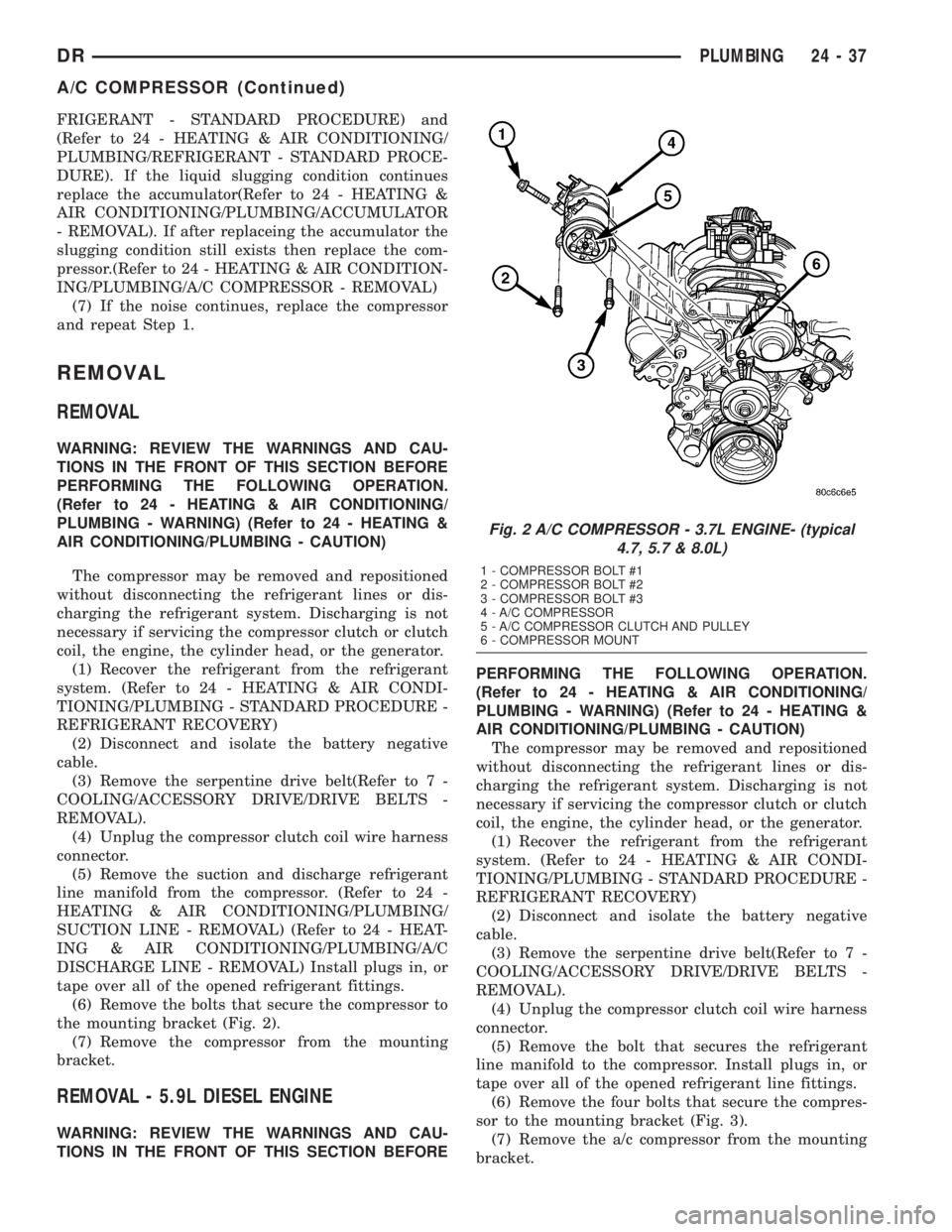
(6) Remove the bolts that secure the compressor to
the mounting bracket (Fig. 2).
(7) Remove the compressor from the mounting
bracket.
REMOVAL - 5.9L DIESEL ENGINE
WARNING: REVIEW THE WARNINGS AND CAU-
TIONS IN THE FRONT OF THIS SECTION BEFOREPERFORMING THE FOLLOWING OPERATION.
(Refer to 24 - HEATING & AIR CONDITIONING/
PLUMBING - WARNING) (Refer to 24 - HEATING &
AIR CONDITIONING/PLUMBING - CAUTION)
The compressor may be removed and repositioned
without disconnecting the refrigerant lines or dis-
charging the refrigerant system. Discharging is not
necessary if servicing the compressor clutch or clutch
coil, the engine, the cylinder head, or the generator.
(1) Recover the refrigerant from the refrigerant
system. (Refer to 24 - HEATING & AIR CONDI-
TIONING/PLUMBING - STANDARD PROCEDURE -
REFRIGERANT RECOVERY)
(2) Disconnect and isolate the battery negative
cable.
(3) Remove the serpentine drive belt(Refer to 7 -
COOLING/ACCESSORY DRIVE/DRIVE BELTS -
REMOVAL).
(4) Unplug the compressor clutch coil wire harness
connector.
(5) Remove the bolt that secures the refrigerant
line manifold to the compressor. Install plugs in, or
tape over all of the opened refrigerant line fittings.
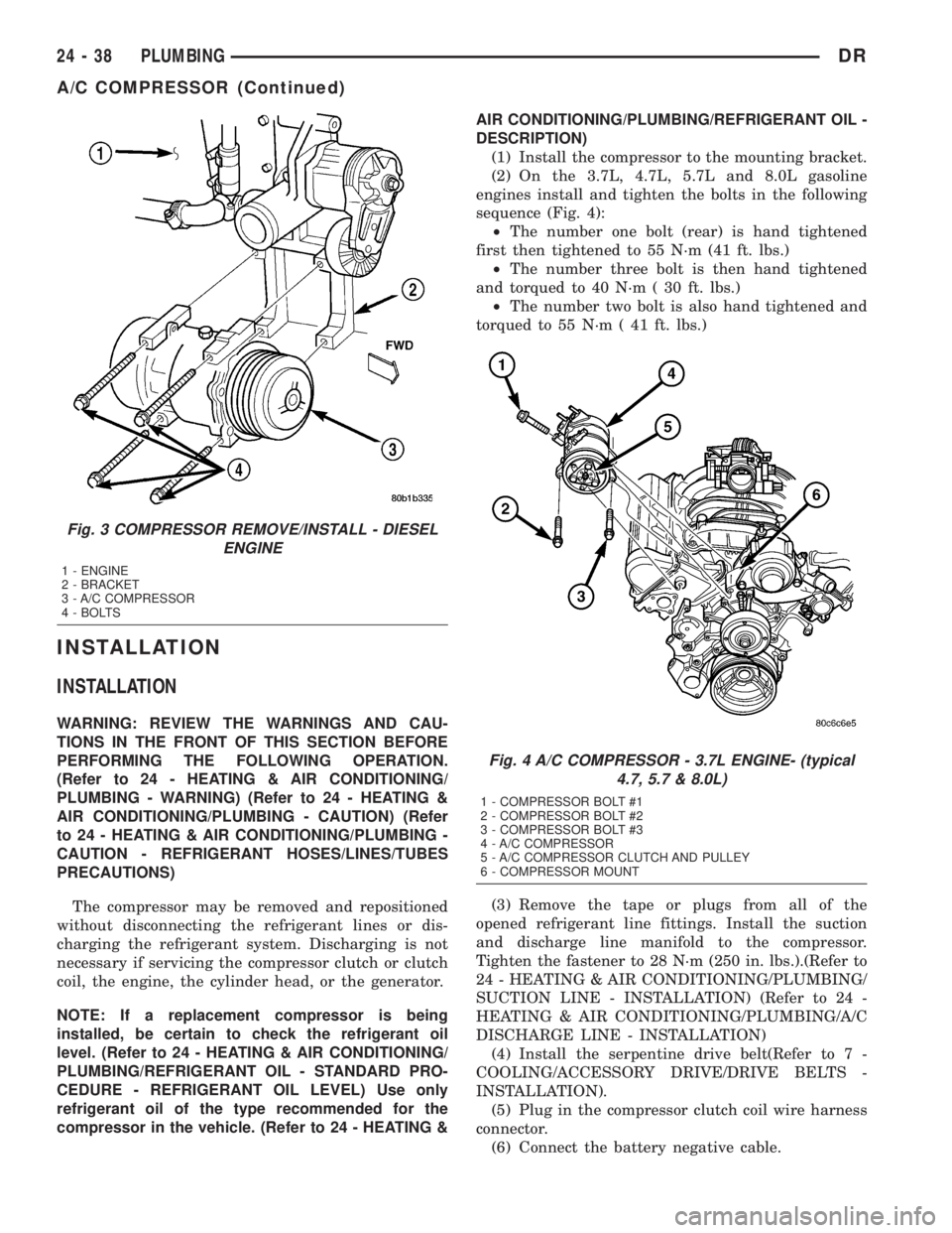
(6) Remove the four bolts that secure the compres-
sor to the mounting bracket (Fig. 3).
(7) Remove the a/c compressor from the mounting
bracket.
Fig. 2 A/C COMPRESSOR - 3.7L ENGINE- (typical
4.7, 5.7 & 8.0L)
1 - COMPRESSOR BOLT #1
2 - COMPRESSOR BOLT #2
3 - COMPRESSOR BOLT #3
4 - A/C COMPRESSOR
5 - A/C COMPRESSOR CLUTCH AND PULLEY
6 - COMPRESSOR MOUNT
DRPLUMBING 24 - 37
A/C COMPRESSOR (Continued)
Page 2813 of 2895
INSTALLATION
INSTALLATION
WARNING: REVIEW THE WARNINGS AND CAU-
TIONS IN THE FRONT OF THIS SECTION BEFORE
PERFORMING THE FOLLOWING OPERATION.
(Refer to 24 - HEATING & AIR CONDITIONING/
PLUMBING - WARNING) (Refer to 24 - HEATING &
AIR CONDITIONING/PLUMBING - CAUTION) (Refer
to 24 - HEATING & AIR CONDITIONING/PLUMBING -
CAUTION - REFRIGERANT HOSES/LINES/TUBES
PRECAUTIONS)
The compressor may be removed and repositioned
without disconnecting the refrigerant lines or dis-
charging the refrigerant system. Discharging is not
necessary if servicing the compressor clutch or clutch
coil, the engine, the cylinder head, or the generator.
NOTE: If a replacement compressor is being
installed, be certain to check the refrigerant oil
level. (Refer to 24 - HEATING & AIR CONDITIONING/
PLUMBING/REFRIGERANT OIL - STANDARD PRO-
CEDURE - REFRIGERANT OIL LEVEL) Use only
refrigerant oil of the type recommended for the
compressor in the vehicle. (Refer to 24 - HEATING &AIR CONDITIONING/PLUMBING/REFRIGERANT OIL -
DESCRIPTION)
(1) Install the compressor to the mounting bracket.
(2) On the 3.7L, 4.7L, 5.7L and 8.0L gasoline
engines install and tighten the bolts in the following
sequence (Fig. 4):
²The number one bolt (rear) is hand tightened
first then tightened to 55 N´m (41 ft. lbs.)
²The number three bolt is then hand tightened
and torqued to 40 N´m ( 30 ft. lbs.)
²The number two bolt is also hand tightened and
torqued to 55 N´m ( 41 ft. lbs.)
(3) Remove the tape or plugs from all of the
opened refrigerant line fittings. Install the suction
and discharge line manifold to the compressor.
Tighten the fastener to 28 N´m (250 in. lbs.).(Refer to
24 - HEATING & AIR CONDITIONING/PLUMBING/
SUCTION LINE - INSTALLATION) (Refer to 24 -
HEATING & AIR CONDITIONING/PLUMBING/A/C
DISCHARGE LINE - INSTALLATION)
(4) Install the serpentine drive belt(Refer to 7 -
COOLING/ACCESSORY DRIVE/DRIVE BELTS -
INSTALLATION).
(5) Plug in the compressor clutch coil wire harness
connector.
(6) Connect the battery negative cable.
Fig. 3 COMPRESSOR REMOVE/INSTALL - DIESEL
ENGINE
1 - ENGINE
2 - BRACKET
3 - A/C COMPRESSOR
4 - BOLTS
Fig. 4 A/C COMPRESSOR - 3.7L ENGINE- (typical
4.7, 5.7 & 8.0L)
1 - COMPRESSOR BOLT #1
2 - COMPRESSOR BOLT #2
3 - COMPRESSOR BOLT #3
4 - A/C COMPRESSOR
5 - A/C COMPRESSOR CLUTCH AND PULLEY
6 - COMPRESSOR MOUNT
24 - 38 PLUMBINGDR
A/C COMPRESSOR (Continued)