2003 DODGE RAM timing belt
[x] Cancel search: timing beltPage 1629 of 2895
(1) Install the push rods in the same order as
removed.
(2) Install rocker arm assemblies in the same
order as removed. Tighten the rocker arm bolts to 53
N´m (40 ft. lbs.) torque.
(3) Install cylinder head cover and gasket (Refer to
9 - ENGINE/CYLINDER HEAD/CYLINDER HEAD
COVER(S) - INSTALLATION).
(4) Connect spark plug wires.
ENGINE BLOCK
CLEANING
Clean cylinder block thoroughly and check all core
hole plugs for evidence of leaking.
INSPECTION
Examine block for cracks or fractures.
The cylinder walls should be checked for out-of-
round and taper with Cylinder Bore Indicator Tool,
Special tool 6879 or equivalent. The cylinder block
should be bored and honed with new pistons and
rings fitted if:
²The cylinder bores show more than 0.127 mm
(0.005 inch) out-of-round.
²The cylinder bores show a taper of more than
0.254 mm (0.010 inch).
²The cylinder walls are badly scuffed or scored.
Boring and honing operation should be closely coor-
dinated with the fitting of pistons and rings so spec-
ified clearances may be maintained.
CAMSHAFT & BEARINGS (IN
BLOCK)
REMOVAL
REMOVALÐCAMSHAFT BEARINGS
This procedure requires that the engine is removed
from the vehicle.
(1) With engine completely disassembled, drive out
rear cam bearing core hole plug.
NOTE: It is not advisable to attempt to replace cam-
shaft bearings unless special removal and installa-
tion tools are available, such as recommended tool
8544 Camshaft Bushing Remover Installer.
(2) Using recommended tool 8544 Camshaft Bush-
ing Remover Installer, Drive out bearing shells.
REMOVALÐCAMSHAFT
(1) Remove rocker arms and push rods (Refer to 9
- ENGINE/CYLINDER HEAD/ROCKER ARM /
ADJUSTER ASSY - REMOVAL). Identify each part
so it can be installed in its original location.
NOTE: The 4 corner tappets can not be removed
without removing the cylinder heads and gaskets.
However, they can be lifted and retained for cam-
shaft removal.
(2) Remove the Bolts retaining the yoke retaining
spider. Remove the yoke retaining spider, tappet
aligning yokes and tappets.
(3) Remove upper and lower intake manifolds
(Refer to 9 - ENGINE/MANIFOLDS/INTAKE MANI-
FOLD - REMOVAL).
(4) Remove timing chain cover (Refer to 9 -
ENGINE/VALVE TIMING/TIMING BELT / CHAIN
COVER(S) - REMOVAL) and timing chain and
sprockets (Refer to 9 - ENGINE/VALVE TIMING/
TIMING BELT/CHAIN AND SPROCKETS -
REMOVAL).
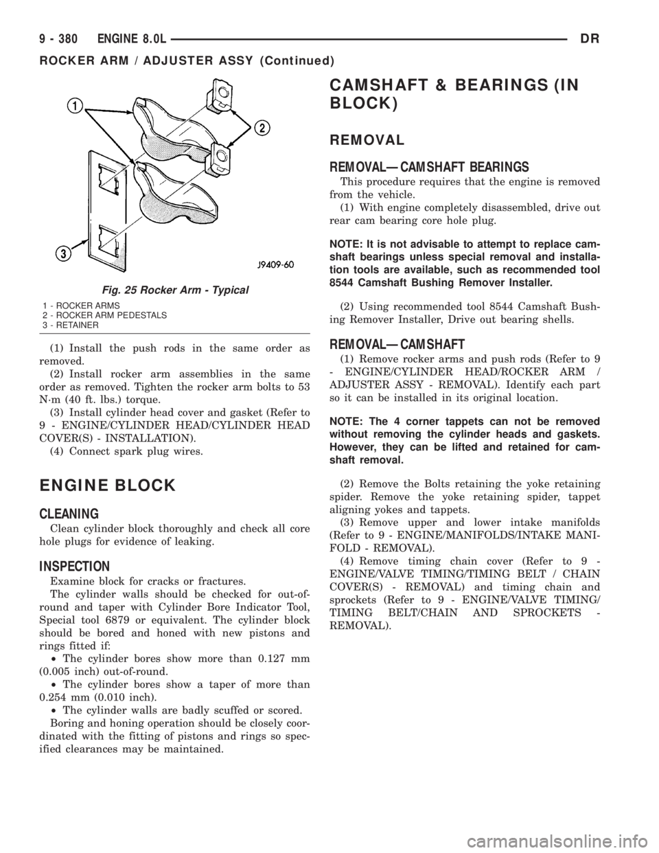
Fig. 25 Rocker Arm - Typical
1 - ROCKER ARMS
2 - ROCKER ARM PEDESTALS
3 - RETAINER
9 - 380 ENGINE 8.0LDR
ROCKER ARM / ADJUSTER ASSY (Continued)
Page 1630 of 2895
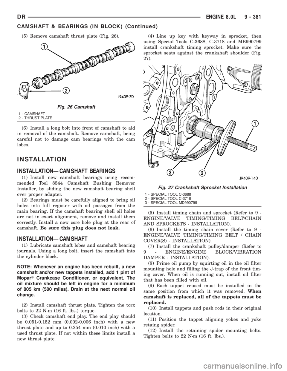
(5) Remove camshaft thrust plate (Fig. 26).
(6) Install a long bolt into front of camshaft to aid
in removal of the camshaft. Remove camshaft, being
careful not to damage cam bearings with the cam
lobes.
INSTALLATION
INSTALLATIONÐCAMSHAFT BEARINGS
(1) Install new camshaft bearings using recom-
mended Tool 8544 Camshaft Bushing Remover
Installer, by sliding the new camshaft bearing shell
over proper adapter.
(2) Bearings must be carefully aligned to bring oil
holes into full register with oil passages from the
main bearing. If the camshaft bearing shell oil holes
are not in exact alignment, remove and install them
correctly. Install a new core hole plug at the rear of
camshaft.Be sure this plug does not leak.
INSTALLATIONÐCAMSHAFT
(1) Lubricate camshaft lobes and camshaft bearing
journals. Using a long bolt, insert the camshaft into
the cylinder block.
NOTE: Whenever an engine has been rebuilt, a new
camshaft and/or new tappets installed, add 1 pint of
MoparTCrankcase Conditioner, or equivalent. The
oil mixture should be left in engine for a minimum
of 805 km (500 miles). Drain at the next normal oil
change.
(2) Install camshaft thrust plate. Tighten the torx
bolts to 22 N´m (16 ft. lbs.) torque.
(3) Check camshaft end play. The end play should
be 0.051-0.152 mm (0.002-0.006 inch) with a new
thrust plate and up to 0.254 mm (0.010 inch) with a
used thrust plate. If not within these limits install a
new thrust plate.(4) Line up key with keyway in sprocket, then
using Special Tools C-3688, C-3718 and MB990799
install crankshaft timing sprocket. Make sure the
sprocket seats against the crankshaft shoulder (Fig.
27).
(5) Install timing chain and sprocket (Refer to 9 -
ENGINE/VALVE TIMING/TIMING BELT/CHAIN
AND SPROCKETS - INSTALLATION).
(6) Install the timing chain cover (Refer to 9 -
ENGINE/VALVE TIMING/TIMING BELT / CHAIN
COVER(S) - INSTALLATION).
(7) Install the crankshaft pulley/damper (Refer to
9 - ENGINE/ENGINE BLOCK/VIBRATION
DAMPER - INSTALLATION).
(8) Prime oil pump by squirting oil in the oil filter
mounting hole and filling the J-trap of the front tim-
ing cover. When oil is running out, install oil filter
that has been filled with oil.
(9) Each tappet reused must be installed in the
same position from which it was removed.When
camshaft is replaced, all of the tappets must be
replaced.
(10) Install tappets and push rods in their original
location.
(11) Position the tappet aligning yokes and yoke
retaing spider.
(12) Install the retaining spider mounting bolts.
Tighten bolts to 22 N´m (16 ft. lbs.).
Fig. 26 Camshaft
1 - CAMSHAFT
2 - THRUST PLATE
Fig. 27 Crankshaft Sprocket Installation
1 - SPECIAL TOOL C-3688
2 - SPECIAL TOOL C-3718
3 - SPECIAL TOOL MD990799
DRENGINE 8.0L 9 - 381
CAMSHAFT & BEARINGS (IN BLOCK) (Continued)
Page 1633 of 2895
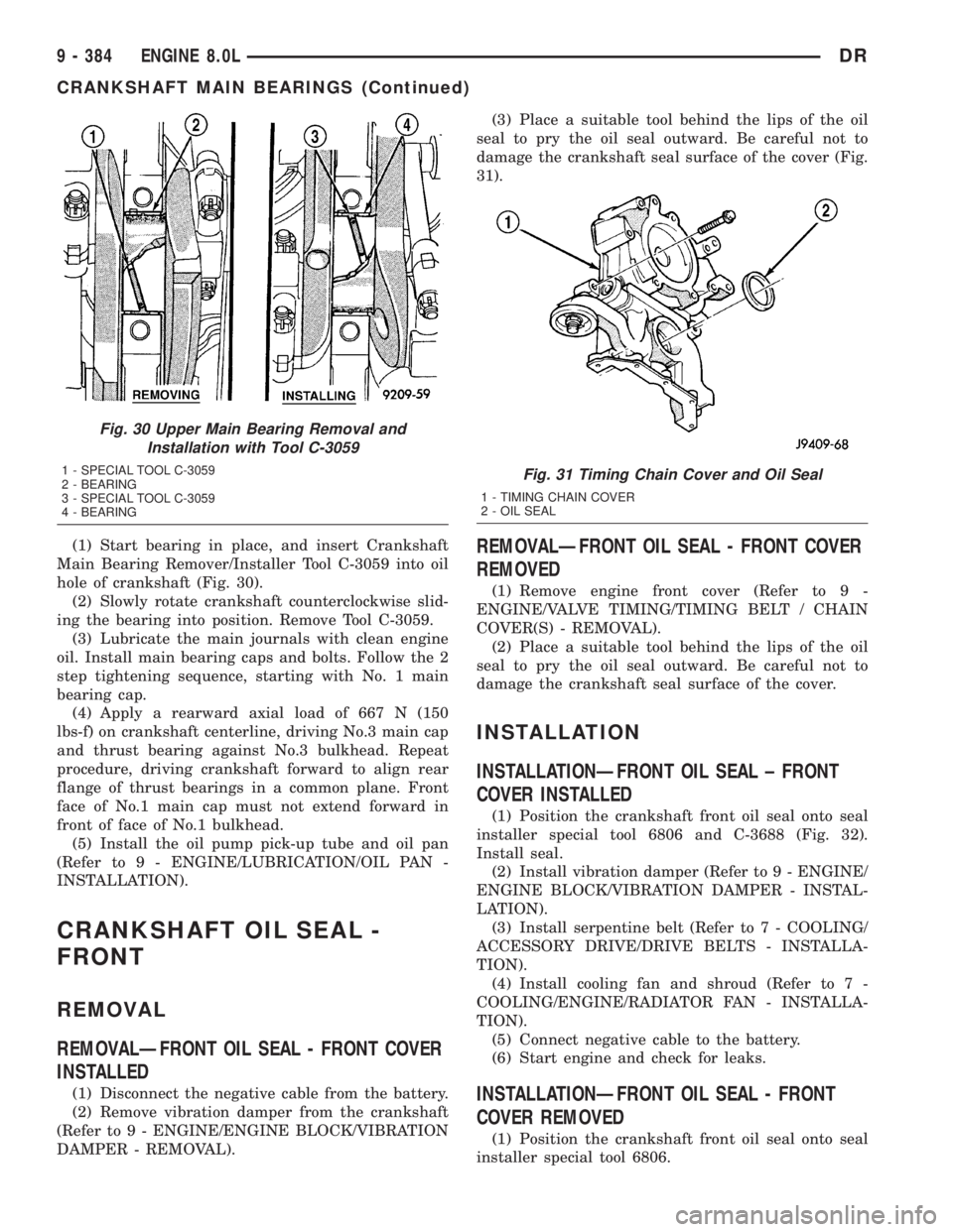
(1) Start bearing in place, and insert Crankshaft
Main Bearing Remover/Installer Tool C-3059 into oil
hole of crankshaft (Fig. 30).
(2) Slowly rotate crankshaft counterclockwise slid-
ing the bearing into position. Remove Tool C-3059.
(3) Lubricate the main journals with clean engine
oil. Install main bearing caps and bolts. Follow the 2
step tightening sequence, starting with No. 1 main
bearing cap.
(4) Apply a rearward axial load of 667 N (150
lbs-f) on crankshaft centerline, driving No.3 main cap
and thrust bearing against No.3 bulkhead. Repeat
procedure, driving crankshaft forward to align rear
flange of thrust bearings in a common plane. Front
face of No.1 main cap must not extend forward in
front of face of No.1 bulkhead.
(5) Install the oil pump pick-up tube and oil pan
(Refer to 9 - ENGINE/LUBRICATION/OIL PAN -
INSTALLATION).
CRANKSHAFT OIL SEAL -
FRONT
REMOVAL
REMOVALÐFRONT OIL SEAL - FRONT COVER
INSTALLED
(1) Disconnect the negative cable from the battery.
(2) Remove vibration damper from the crankshaft
(Refer to 9 - ENGINE/ENGINE BLOCK/VIBRATION
DAMPER - REMOVAL).(3) Place a suitable tool behind the lips of the oil
seal to pry the oil seal outward. Be careful not to
damage the crankshaft seal surface of the cover (Fig.
31).
REMOVALÐFRONT OIL SEAL - FRONT COVER
REMOVED
(1) Remove engine front cover (Refer to 9 -
ENGINE/VALVE TIMING/TIMING BELT / CHAIN
COVER(S) - REMOVAL).
(2) Place a suitable tool behind the lips of the oil
seal to pry the oil seal outward. Be careful not to
damage the crankshaft seal surface of the cover.
INSTALLATION
INSTALLATIONÐFRONT OIL SEAL ± FRONT
COVER INSTALLED
(1) Position the crankshaft front oil seal onto seal
installer special tool 6806 and C-3688 (Fig. 32).
Install seal.
(2) Install vibration damper (Refer to 9 - ENGINE/
ENGINE BLOCK/VIBRATION DAMPER - INSTAL-
LATION).
(3) Install serpentine belt (Refer to 7 - COOLING/
ACCESSORY DRIVE/DRIVE BELTS - INSTALLA-
TION).
(4) Install cooling fan and shroud (Refer to 7 -
COOLING/ENGINE/RADIATOR FAN - INSTALLA-
TION).
(5) Connect negative cable to the battery.
(6) Start engine and check for leaks.
INSTALLATIONÐFRONT OIL SEAL - FRONT
COVER REMOVED
(1) Position the crankshaft front oil seal onto seal
installer special tool 6806.
Fig. 30 Upper Main Bearing Removal and
Installation with Tool C-3059
1 - SPECIAL TOOL C-3059
2 - BEARING
3 - SPECIAL TOOL C-3059
4 - BEARINGFig. 31 Timing Chain Cover and Oil Seal
1 - TIMING CHAIN COVER
2 - OIL SEAL
9 - 384 ENGINE 8.0LDR
CRANKSHAFT MAIN BEARINGS (Continued)
Page 1634 of 2895
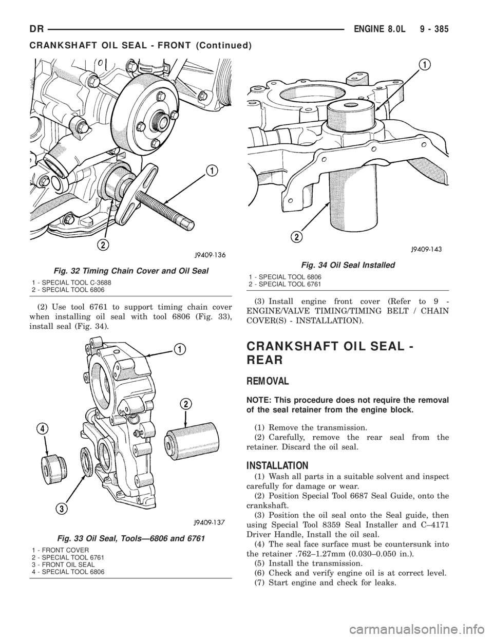
(2) Use tool 6761 to support timing chain cover
when installing oil seal with tool 6806 (Fig. 33),
install seal (Fig. 34).(3) Install engine front cover (Refer to 9 -
ENGINE/VALVE TIMING/TIMING BELT / CHAIN
COVER(S) - INSTALLATION).
CRANKSHAFT OIL SEAL -
REAR
REMOVAL
NOTE: This procedure does not require the removal
of the seal retainer from the engine block.
(1) Remove the transmission.
(2) Carefully, remove the rear seal from the
retainer. Discard the oil seal.
INSTALLATION
(1) Wash all parts in a suitable solvent and inspect
carefully for damage or wear.
(2) Position Special Tool 6687 Seal Guide, onto the
crankshaft.
(3) Position the oil seal onto the Seal guide, then
using Special Tool 8359 Seal Installer and C±4171
Driver Handle, Install the oil seal.
(4) The seal face surface must be countersunk into
the retainer .762±1.27mm (0.030±0.050 in.).
(5) Install the transmission.
(6) Check and verify engine oil is at correct level.
(7) Start engine and check for leaks.
Fig. 32 Timing Chain Cover and Oil Seal
1 - SPECIAL TOOL C-3688
2 - SPECIAL TOOL 6806
Fig. 33 Oil Seal, ToolsÐ6806 and 6761
1 - FRONT COVER
2 - SPECIAL TOOL 6761
3 - FRONT OIL SEAL
4 - SPECIAL TOOL 6806
Fig. 34 Oil Seal Installed
1 - SPECIAL TOOL 6806
2 - SPECIAL TOOL 6761
DRENGINE 8.0L 9 - 385
CRANKSHAFT OIL SEAL - FRONT (Continued)
Page 1647 of 2895
INSTALLATION
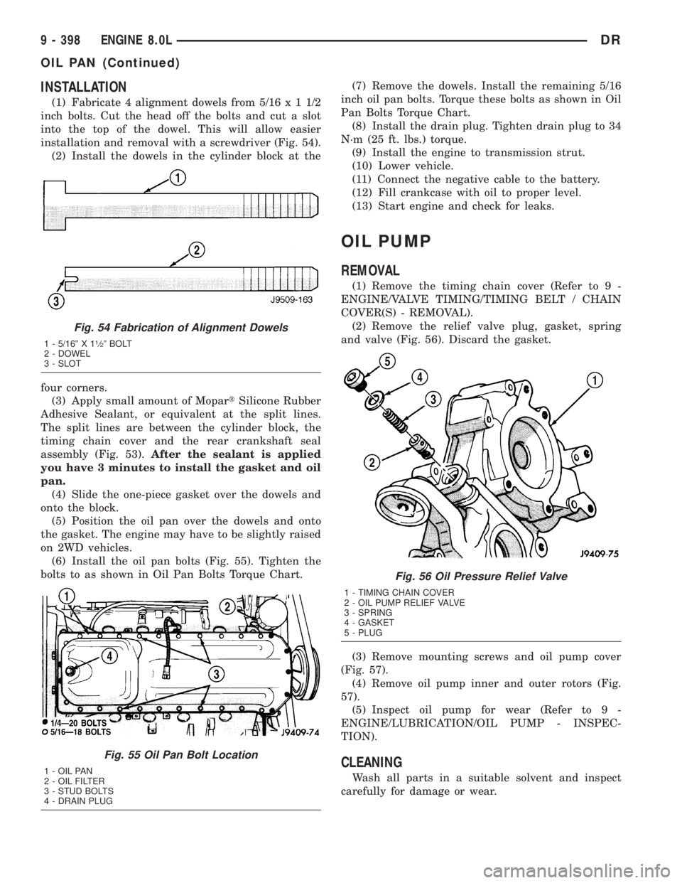
(1) Fabricate 4 alignment dowels from 5/16x11/2
inch bolts. Cut the head off the bolts and cut a slot
into the top of the dowel. This will allow easier
installation and removal with a screwdriver (Fig. 54).
(2) Install the dowels in the cylinder block at the
four corners.
(3) Apply small amount of MopartSilicone Rubber
Adhesive Sealant, or equivalent at the split lines.
The split lines are between the cylinder block, the
timing chain cover and the rear crankshaft seal
assembly (Fig. 53).After the sealant is applied
you have 3 minutes to install the gasket and oil
pan.
(4) Slide the one-piece gasket over the dowels and
onto the block.
(5) Position the oil pan over the dowels and onto
the gasket. The engine may have to be slightly raised
on 2WD vehicles.
(6) Install the oil pan bolts (Fig. 55). Tighten the
bolts to as shown in Oil Pan Bolts Torque Chart.(7) Remove the dowels. Install the remaining 5/16
inch oil pan bolts. Torque these bolts as shown in Oil
Pan Bolts Torque Chart.
(8) Install the drain plug. Tighten drain plug to 34
N´m (25 ft. lbs.) torque.
(9) Install the engine to transmission strut.
(10) Lower vehicle.
(11) Connect the negative cable to the battery.
(12) Fill crankcase with oil to proper level.
(13) Start engine and check for leaks.
OIL PUMP
REMOVAL
(1) Remove the timing chain cover (Refer to 9 -
ENGINE/VALVE TIMING/TIMING BELT / CHAIN
COVER(S) - REMOVAL).
(2) Remove the relief valve plug, gasket, spring
and valve (Fig. 56). Discard the gasket.
(3) Remove mounting screws and oil pump cover
(Fig. 57).
(4) Remove oil pump inner and outer rotors (Fig.
57).
(5) Inspect oil pump for wear (Refer to 9 -
ENGINE/LUBRICATION/OIL PUMP - INSPEC-
TION).
CLEANING
Wash all parts in a suitable solvent and inspect
carefully for damage or wear.
Fig. 54 Fabrication of Alignment Dowels
1 - 5/16º X 11¤2º BOLT
2 - DOWEL
3 - SLOT
Fig. 55 Oil Pan Bolt Location
1 - OIL PAN
2 - OIL FILTER
3 - STUD BOLTS
4 - DRAIN PLUG
Fig. 56 Oil Pressure Relief Valve
1 - TIMING CHAIN COVER
2 - OIL PUMP RELIEF VALVE
3 - SPRING
4 - GASKET
5 - PLUG
9 - 398 ENGINE 8.0LDR
OIL PAN (Continued)
Page 1649 of 2895
Inspect oil pressure relief valve plunger for scoring
and free operation in its bore. Small marks may be
removed with 400-grit wet or dry sandpaper.
The relief valve spring has a free length of approx-
imately 49.5 mm (1.95 inches). The spring should
test between 100 and 109 N (22.5 and 24.5 pounds)
when compressed to 34 mm (1-11/32 inches). Replace
spring that fails to meet these specifications.
If oil pressure was low and pump is within specifi-
cations, inspect for worn engine bearings or other
reasons for oil pressure loss.
INSTALLATION
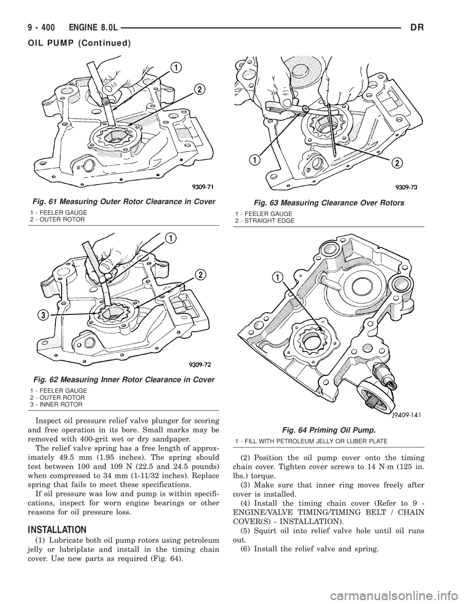
(1) Lubricate both oil pump rotors using petroleum
jelly or lubriplate and install in the timing chain
cover. Use new parts as required (Fig. 64).(2) Position the oil pump cover onto the timing
chain cover. Tighten cover screws to 14 N´m (125 in.
lbs.) torque.
(3) Make sure that inner ring moves freely after
cover is installed.
(4) Install the timing chain cover (Refer to 9 -
ENGINE/VALVE TIMING/TIMING BELT / CHAIN
COVER(S) - INSTALLATION).
(5) Squirt oil into relief valve hole until oil runs
out.
(6) Install the relief valve and spring.
Fig. 61 Measuring Outer Rotor Clearance in Cover
1 - FEELER GAUGE
2 - OUTER ROTOR
Fig. 62 Measuring Inner Rotor Clearance in Cover
1 - FEELER GAUGE
2 - OUTER ROTOR
3 - INNER ROTOR
Fig. 63 Measuring Clearance Over Rotors
1 - FEELER GAUGE
2 - STRAIGHT EDGE
Fig. 64 Priming Oil Pump.
1 - FILL WITH PETROLEUM JELLY OR LUBER PLATE
9 - 400 ENGINE 8.0LDR
OIL PUMP (Continued)
Page 1653 of 2895
REMOVAL
(1) Disconnect the negative cable from the battery.
(2) Raise and support the vehicle.
(3) Remove the bolts and nuts attaching the
exhaust pipe to the engine exhaust manifold..
(4) Lower the vehicle.
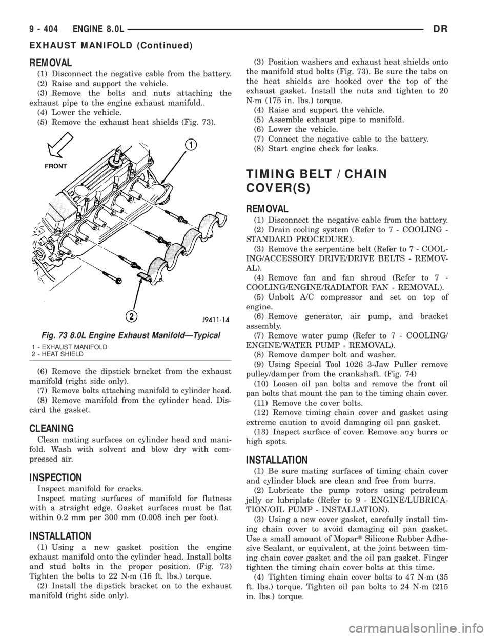
(5) Remove the exhaust heat shields (Fig. 73).
(6) Remove the dipstick bracket from the exhaust
manifold (right side only).
(7)
Remove bolts attaching manifold to cylinder head.
(8) Remove manifold from the cylinder head. Dis-
card the gasket.
CLEANING
Clean mating surfaces on cylinder head and mani-
fold. Wash with solvent and blow dry with com-
pressed air.
INSPECTION
Inspect manifold for cracks.
Inspect mating surfaces of manifold for flatness
with a straight edge. Gasket surfaces must be flat
within 0.2 mm per 300 mm (0.008 inch per foot).
INSTALLATION
(1) Using a new gasket position the engine
exhaust manifold onto the cylinder head. Install bolts
and stud bolts in the proper position. (Fig. 73)
Tighten the bolts to 22 N´m (16 ft. lbs.) torque.
(2) Install the dipstick bracket on to the exhaust
manifold (right side only).(3) Position washers and exhaust heat shields onto
the manifold stud bolts (Fig. 73). Be sure the tabs on
the heat shields are hooked over the top of the
exhaust gasket. Install the nuts and tighten to 20
N´m (175 in. lbs.) torque.
(4) Raise and support the vehicle.
(5) Assemble exhaust pipe to manifold.
(6) Lower the vehicle.
(7) Connect the negative cable to the battery.
(8) Start engine check for leaks.
TIMING BELT / CHAIN
COVER(S)
REMOVAL
(1) Disconnect the negative cable from the battery.
(2) Drain cooling system (Refer to 7 - COOLING -
STANDARD PROCEDURE).
(3) Remove the serpentine belt (Refer to 7 - COOL-
ING/ACCESSORY DRIVE/DRIVE BELTS - REMOV-
AL).
(4) Remove fan and fan shroud (Refer to 7 -
COOLING/ENGINE/RADIATOR FAN - REMOVAL).
(5) Unbolt A/C compressor and set on top of
engine.
(6) Remove generator, air pump, and bracket
assembly.
(7) Remove water pump (Refer to 7 - COOLING/
ENGINE/WATER PUMP - REMOVAL).
(8) Remove damper bolt and washer.
(9) Using Special Tool 1026 3-Jaw Puller remove
pulley/damper from the crankshaft. (Fig. 74)
(10)
Loosen oil pan bolts and remove the front oil
pan bolts that mount the pan to the timing chain cover.
(11) Remove the cover bolts.
(12) Remove timing chain cover and gasket using
extreme caution to avoid damaging oil pan gasket.
(13) Inspect surface of cover. Remove any burrs or
high spots.
INSTALLATION
(1) Be sure mating surfaces of timing chain cover
and cylinder block are clean and free from burrs.
(2) Lubricate the pump rotors using petroleum
jelly or lubriplate (Refer to 9 - ENGINE/LUBRICA-
TION/OIL PUMP - INSTALLATION).
(3) Using a new cover gasket, carefully install tim-
ing chain cover to avoid damaging oil pan gasket.
Use a small amount of MopartSilicone Rubber Adhe-
sive Sealant, or equivalent, at the joint between tim-
ing chain cover gasket and the oil pan gasket. Finger
tighten the timing chain cover bolts at this time.
(4) Tighten timing chain cover bolts to 47 N´m (35
ft. lbs.) torque. Tighten oil pan bolts to 24 N´m (215
in. lbs.) torque.
Fig. 73 8.0L Engine Exhaust ManifoldÐTypical
1 - EXHAUST MANIFOLD
2 - HEAT SHIELD
9 - 404 ENGINE 8.0LDR
EXHAUST MANIFOLD (Continued)
Page 1654 of 2895
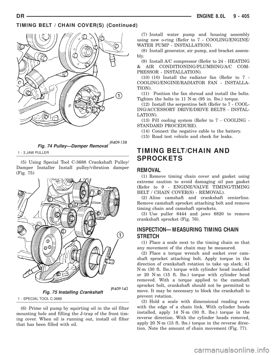
(5) Using Special Tool C-3688 Crankshaft Pulley/
Damper Installer Install pulley/vibration damper
(Fig. 75)
(6) Prime oil pump by squirting oil in the oil filter
mounting hole and filling the J-trap of the front tim-
ing cover. When oil is running out, install oil filter
that has been filled with oil.(7) Install water pump and housing assembly
using new o-ring (Refer to 7 - COOLING/ENGINE/
WATER PUMP - INSTALLATION).
(8) Install generator, air pump, and bracket assem-
bly.
(9) Install A/C compressor (Refer to 24 - HEATING
& AIR CONDITIONING/PLUMBING/A/C COM-
PRESSOR - INSTALLATION).
(10) (10) Install the radiator fan (Refer to 7 -
COOLING/ENGINE/RADIATOR FAN - INSTALLA-
TION).
(11) Position the fan shroud and install the bolts.
Tighten the bolts to 11 N´m (95 in. lbs.) torque.
(12) Install the serpentine belt (Refer to 7 - COOL-
ING/ACCESSORY DRIVE/DRIVE BELTS - INSTAL-
LATION).
(13) Fill cooling system (Refer to 7 - COOLING -
STANDARD PROCEDURE).
(14) Connect the negative cable to the battery.
(15) Road test vehicle and check for leaks.
TIMING BELT/CHAIN AND
SPROCKETS
REMOVAL
(1) Remove timing chain cover and gasket using
extreme caution to avoid damaging oil pan gasket
(Refer to 9 - ENGINE/VALVE TIMING/TIMING
BELT / CHAIN COVER(S) - REMOVAL).
(2) Aline camshaft and crankshaft centerline.
Remove camshaft sprocket attaching bolt and remove
timing chain and camshaft sprockets.
(3) Use puller 6444 and jaws 6820 to remove
crankshaft sprocket (Fig. 76).
INSPECTIONÐMEASURING TIMING CHAIN
STRETCH
(1) Place a scale next to the timing chain so that
any movement of the chain may be measured.
(2) Place a torque wrench and socket over cam-
shaft sprocket attaching bolt. Apply torque in the
direction of crankshaft rotation to take up slack; 41
N´m (30 ft. lbs.) torque with cylinder head installed
or 20 N´m (15 ft. lbs.) torque with cylinder head
removed. With a torque applied to the camshaft
sprocket bolt, crankshaft should not be permitted to
move. It may be necessary to block the crankshaft to
prevent rotation.
(3) Hold a scale with dimensional reading even
with the edge of a chain link. With cylinder heads
installed, apply 14 N´m (30 ft. lbs.) torque in the
reverse direction. With the cylinder heads removed,
apply 20 N´m (15 ft. lbs.) torque in the reverse direc-
tion. Note the amount of chain movement (Fig. 77).
Fig. 74 PulleyÐDamper Removal
1-3JAWPULLER
Fig. 75 Installing Crankshaft
1 - SPECIAL TOOL C-3688
DRENGINE 8.0L 9 - 405
TIMING BELT / CHAIN COVER(S) (Continued)