2003 DODGE RAM engine wiring
[x] Cancel search: engine wiringPage 1788 of 2895
INTAKE AIR HEATER
DESCRIPTION
The intake manifold air heater element assembly
is located in the top of the intake manifold.
OPERATION
The air heater elements are used to heat incoming
air to the intake manifold. This is done to help
engine starting and improve driveability with cool or
cold outside temperatures.
Electrical supply for the 2 air heater elements is
controlled by the Engine Control Module (ECM)
through the 2 air heater relays. Refer to Intake Man-
ifold Air Heater Relays for more information.
Two heavy-duty cables connect the 2 air heater ele-
ments to the 2 air heater relays. Each of these cables
will supply approximately 95 amps at 12 volts to an
individual heating element within the heater block
assembly.
Refer to the Powertrain Diagnostic Procedures
manual for an electrical operation and complete
description of the intake heaters, including pre-heat
and post-heat cycles.
REMOVAL
If servicing either of the heater elements, the
entire block/element assembly must be replaced.
(1) Disconnect both negative battery cables at both
batteries. Cover and isolate ends of both cables.
(2) Remove both the intake manifold air intake
tube (above injection pump), and its rubber connector
hose (Fig. 27).
(3) Lift 2 rubber covers (Fig. 28) to gain access to 2
positive (+) cable nuts. Remove these 2 nuts (Fig. 29)
and remove 2 cables from studs.
(4) Disconnect ground strap (Fig. 28) at heater ele-
ment stud.
(5) Remove wiring harness clips.
(6) Remove engine oil dipstick tube bracket from
air inlet connection and fuel filter housing.
(7) Remove 4 housing mounting bolts (Fig. 28) and
remove heater element assembly.
INSTALLATION
If servicing either of the heater elements, the
entire block/element assembly must be replaced.
(1) Using 2 new gaskets, position element assem-
bly and air housing to intake manifold.
(2) Position ground cable to air housing.
(3) Install 4 housing bolts and tighten to 24 N´m
(18 ft. lbs.) torque.
(4) Connect 2 positive (+) heater cables at cable
mounting studs.Do not allow either of the cable
eyelets to contact any other metal source other
than the cable nuts/studs.
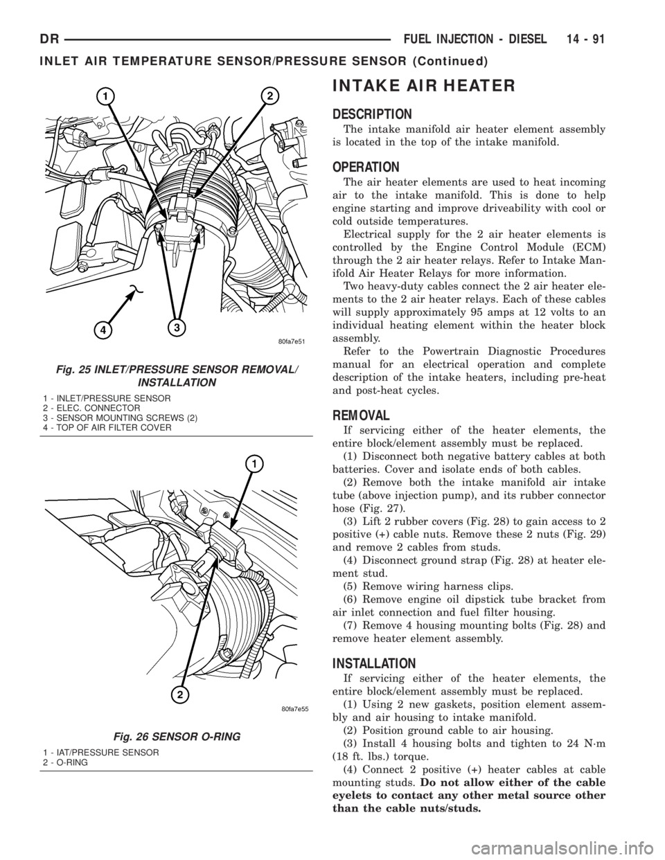
Fig. 25 INLET/PRESSURE SENSOR REMOVAL/
INSTALLATION
1 - INLET/PRESSURE SENSOR
2 - ELEC. CONNECTOR
3 - SENSOR MOUNTING SCREWS (2)
4 - TOP OF AIR FILTER COVER
Fig. 26 SENSOR O-RING
1 - IAT/PRESSURE SENSOR
2 - O-RING
DRFUEL INJECTION - DIESEL 14 - 91
INLET AIR TEMPERATURE SENSOR/PRESSURE SENSOR (Continued)
Page 1790 of 2895
Refer to Powertrain Diagnostic Procedures for an
electrical operation and complete description of the
intake heaters, including pre-heat and post-heat
cycles.
REMOVAL
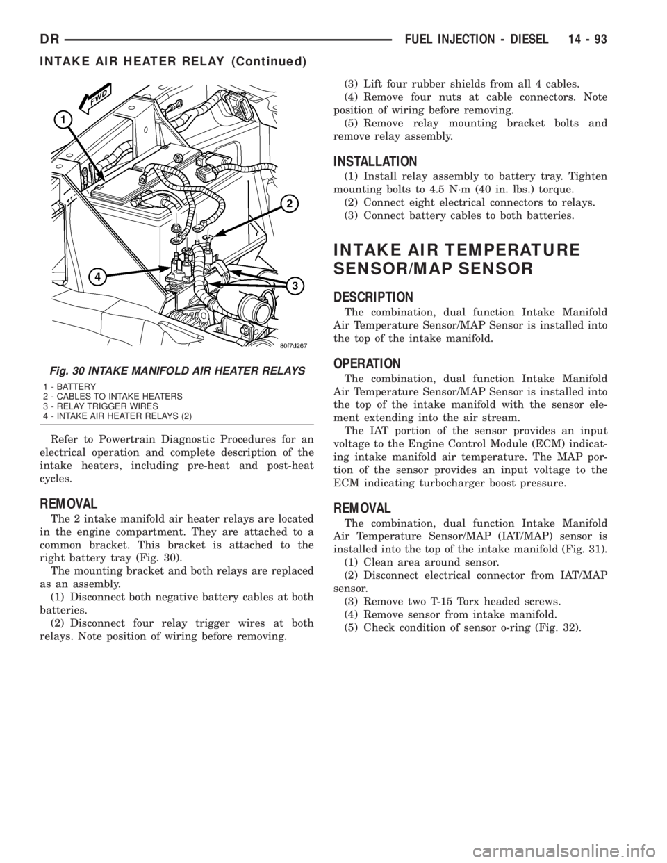
The 2 intake manifold air heater relays are located
in the engine compartment. They are attached to a
common bracket. This bracket is attached to the
right battery tray (Fig. 30).
The mounting bracket and both relays are replaced
as an assembly.
(1) Disconnect both negative battery cables at both
batteries.
(2) Disconnect four relay trigger wires at both
relays. Note position of wiring before removing.(3) Lift four rubber shields from all 4 cables.
(4) Remove four nuts at cable connectors. Note
position of wiring before removing.
(5) Remove relay mounting bracket bolts and
remove relay assembly.
INSTALLATION
(1) Install relay assembly to battery tray. Tighten
mounting bolts to 4.5 N´m (40 in. lbs.) torque.
(2) Connect eight electrical connectors to relays.
(3) Connect battery cables to both batteries.
INTAKE AIR TEMPERATURE
SENSOR/MAP SENSOR
DESCRIPTION
The combination, dual function Intake Manifold
Air Temperature Sensor/MAP Sensor is installed into
the top of the intake manifold.
OPERATION
The combination, dual function Intake Manifold
Air Temperature Sensor/MAP Sensor is installed into
the top of the intake manifold with the sensor ele-
ment extending into the air stream.
The IAT portion of the sensor provides an input
voltage to the Engine Control Module (ECM) indicat-
ing intake manifold air temperature. The MAP por-
tion of the sensor provides an input voltage to the
ECM indicating turbocharger boost pressure.
REMOVAL
The combination, dual function Intake Manifold
Air Temperature Sensor/MAP (IAT/MAP) sensor is
installed into the top of the intake manifold (Fig. 31).
(1) Clean area around sensor.
(2) Disconnect electrical connector from IAT/MAP
sensor.
(3) Remove two T-15 Torx headed screws.
(4) Remove sensor from intake manifold.
(5) Check condition of sensor o-ring (Fig. 32).
Fig. 30 INTAKE MANIFOLD AIR HEATER RELAYS
1 - BATTERY
2 - CABLES TO INTAKE HEATERS
3 - RELAY TRIGGER WIRES
4 - INTAKE AIR HEATER RELAYS (2)
DRFUEL INJECTION - DIESEL 14 - 93
INTAKE AIR HEATER RELAY (Continued)
Page 1990 of 2895
CONDITION POSSIBLE CAUSES CORRECTION
NO 4-3 DOWNSHIFT
WHEN CONTROL SWITCH
IS TURNED OFF1. Control Switch Open/Shorted. 1. Test and replace switch if faulty.
2. Overdrive Solenoid Connector
Shorted.2. Test solenoids and replace if seized or
shorted.
3. PCM Malfunction. 3. Test with DRBTscan tool. Replace PCM
if faulty.
4. Valve Body Stuck Valves. 4. Repair stuck 3-4, lockup or lockup timing
valve.
CLUNK NOISE FROM
DRIVELINE ON CLOSED
THROTTLE 4-3
DOWNSHIFT1. Transmission Fluid Low. 1. Add Fluid.
2. Throttle Cable Mis-adjusted. 2. Adjust cable.
3. Overdrive Clutch Select Spacer
Wrong Spacer.3. Replace overdrive piston thrust plate
spacer.
3-4 UPSHIFT OCCURS
IMMEDIATELY AFTER 2-3
SHIFT1. Overdrive Solenoid Connector or
Wiring Shorted.1. Test connector and wiring for loose
connections, shorts or ground and repair as
needed.
2. TPS Malfunction. 2. Test TPS and replace as necessary.
Check with DRBTscan tool.
3. PCM Malfunction. 3. Test PCM with DRBTscan tool and
replace controller if faulty.
4. Overdrive Solenoid Malfunction. 4. Replace solenoid.
5. Valve Body Malfunction. 5. Remove, disassemble, clean and inspect
valve body components. Make sure all
valves and plugs slide freely in bores.
Polish valves with crocus cloth if needed.
WHINE/NOISE RELATED
TO ENGINE SPEED1. Fluid Level Low. 1. Add fluid and check for leaks.
2. Shift Cable Incorrect Routing. 2. Check shift cable for correct routing.
Should not touch engine or bell housing.
DRAUTOMATIC TRANSMISSION - 46RE 21 - 151
AUTOMATIC TRANSMISSION - 46RE (Continued)
Page 2171 of 2895
CONDITION POSSIBLE CAUSES CORRECTION
NO 4-3 DOWNSHIFT
WHEN CONTROL SWITCH
IS TURNED OFF1. Control Switch Open/Shorted. 1. Test and replace switch if faulty.
2. Overdrive Solenoid Connector
Shorted.2. Test solenoids and replace if seized or
shorted.
3. PCM Malfunction. 3. Test with DRBTscan tool. Replace PCM
if faulty.
4. Valve Body Stuck Valves. 4. Repair stuck 3-4, lockup or lockup timing
valve.
CLUNK NOISE FROM
DRIVELINE ON CLOSED
THROTTLE 4-3
DOWNSHIFT1. Transmission Fluid Low. 1. Add Fluid.
2. Throttle Cable Mis-adjusted. 2. Adjust cable.
3. Overdrive Clutch Select Spacer
Wrong Spacer.3. Replace overdrive piston thrust plate
spacer.
3-4 UPSHIFT OCCURS
IMMEDIATELY AFTER 2-3
SHIFT1. Overdrive Solenoid Connector or
Wiring Shorted.1. Test connector and wiring for loose
connections, shorts or ground and repair as
needed.
2. TPS Malfunction. 2. Test TPS and replace as necessary.
Check with DRBTscan tool.
3. PCM Malfunction. 3. Test PCM with DRBTscan tool and
replace controller if faulty.
4. Overdrive Solenoid Malfunction. 4. Replace solenoid.
5. Valve Body Malfunction. 5. Remove, disassemble, clean and inspect
valve body components. Make sure all
valves and plugs slide freely in bores.
Polish valves with crocus cloth if needed.
WHINE/NOISE RELATED
TO ENGINE SPEED1. Fluid Level Low. 1. Add fluid and check for leaks.
2. Shift Cable Incorrect Routing. 2. Check shift cable for correct routing.
Should not touch engine or bell housing.
21 - 332 AUTOMATIC TRANSMISSION - 48REDR
AUTOMATIC TRANSMISSION - 48RE (Continued)
Page 2398 of 2895
REMOVAL
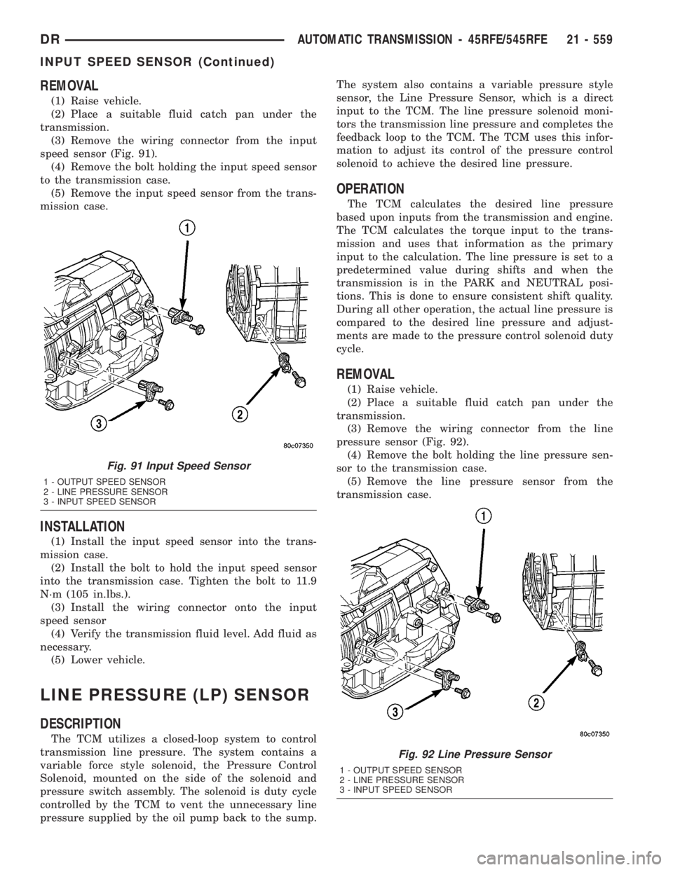
(1) Raise vehicle.
(2) Place a suitable fluid catch pan under the
transmission.
(3) Remove the wiring connector from the input
speed sensor (Fig. 91).
(4) Remove the bolt holding the input speed sensor
to the transmission case.
(5) Remove the input speed sensor from the trans-
mission case.
INSTALLATION
(1) Install the input speed sensor into the trans-
mission case.
(2) Install the bolt to hold the input speed sensor
into the transmission case. Tighten the bolt to 11.9
N´m (105 in.lbs.).
(3) Install the wiring connector onto the input
speed sensor
(4) Verify the transmission fluid level. Add fluid as
necessary.
(5) Lower vehicle.
LINE PRESSURE (LP) SENSOR
DESCRIPTION
The TCM utilizes a closed-loop system to control
transmission line pressure. The system contains a
variable force style solenoid, the Pressure Control
Solenoid, mounted on the side of the solenoid and
pressure switch assembly. The solenoid is duty cycle
controlled by the TCM to vent the unnecessary line
pressure supplied by the oil pump back to the sump.The system also contains a variable pressure style
sensor, the Line Pressure Sensor, which is a direct
input to the TCM. The line pressure solenoid moni-
tors the transmission line pressure and completes the
feedback loop to the TCM. The TCM uses this infor-
mation to adjust its control of the pressure control
solenoid to achieve the desired line pressure.
OPERATION
The TCM calculates the desired line pressure
based upon inputs from the transmission and engine.
The TCM calculates the torque input to the trans-
mission and uses that information as the primary
input to the calculation. The line pressure is set to a
predetermined value during shifts and when the
transmission is in the PARK and NEUTRAL posi-
tions. This is done to ensure consistent shift quality.
During all other operation, the actual line pressure is
compared to the desired line pressure and adjust-
ments are made to the pressure control solenoid duty
cycle.
REMOVAL
(1) Raise vehicle.
(2) Place a suitable fluid catch pan under the
transmission.
(3) Remove the wiring connector from the line
pressure sensor (Fig. 92).
(4) Remove the bolt holding the line pressure sen-
sor to the transmission case.
(5) Remove the line pressure sensor from the
transmission case.
Fig. 91 Input Speed Sensor
1 - OUTPUT SPEED SENSOR
2 - LINE PRESSURE SENSOR
3 - INPUT SPEED SENSOR
Fig. 92 Line Pressure Sensor
1 - OUTPUT SPEED SENSOR
2 - LINE PRESSURE SENSOR
3 - INPUT SPEED SENSOR
DRAUTOMATIC TRANSMISSION - 45RFE/545RFE 21 - 559
INPUT SPEED SENSOR (Continued)
Page 2406 of 2895
into the appropriate oil pump valve body bore (Fig.
102) (Fig. 103).
(4) Place the separator plate onto the oil pump
body (Fig. 101).
(5) Install the screws to hold the separator plate
onto the oil pump body (Fig. 101). Tighten the screws
to 4.5 N´m (40 in.lbs.).
(6) Position the oil pump cover onto the locating
dowels (Fig. 100).
(7) Seat the two oil pump halves together and
install all bolts finger tight.
(8) Torque all bolts down slowly starting in the
center and working outward. The correct torque is
4.5 N´m (40 in.lbs.).
(9) Verify that the oil pump gears rotate freely and
smoothly.
(10) Position the reaction shaft support into the oil
pump (Fig. 100).
(11) Install and torque the bolts to hold the reac-
tion shaft support to the oil pump (Fig. 100). The cor-
rect torque is 12 N´m (105 in.lbs.).
OIL PUMP FRONT SEAL
REMOVAL
(1) Remove transmission from the vehicle.
(2) Remove the torque converter from the trans-
mission.
(3) Using a screw mounted in a slide hammer,
remove the oil pump front seal.
INSTALLATION
(1) Clean seal bore of the oil pump of any residue
or particles from the original seal.
(2) Install new oil seal in the oil pump housing
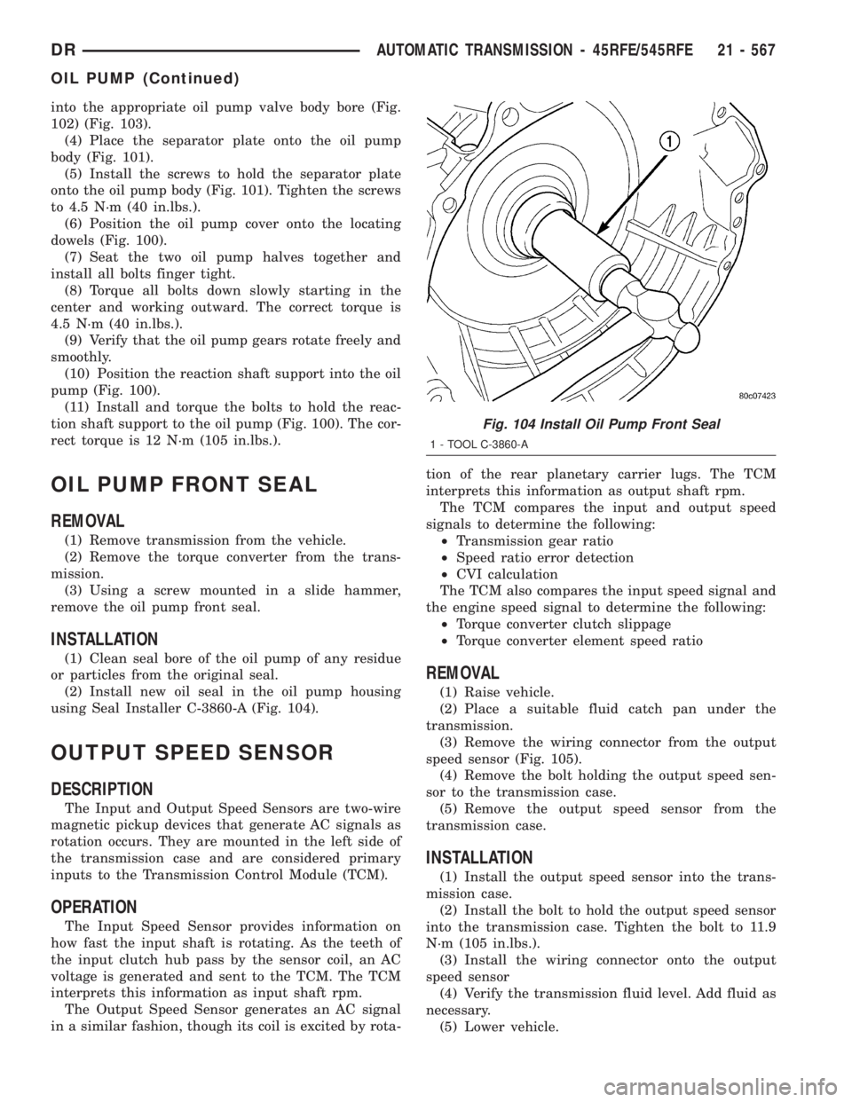
using Seal Installer C-3860-A (Fig. 104).
OUTPUT SPEED SENSOR
DESCRIPTION
The Input and Output Speed Sensors are two-wire
magnetic pickup devices that generate AC signals as
rotation occurs. They are mounted in the left side of
the transmission case and are considered primary
inputs to the Transmission Control Module (TCM).
OPERATION
The Input Speed Sensor provides information on
how fast the input shaft is rotating. As the teeth of
the input clutch hub pass by the sensor coil, an AC
voltage is generated and sent to the TCM. The TCM
interprets this information as input shaft rpm.
The Output Speed Sensor generates an AC signal
in a similar fashion, though its coil is excited by rota-tion of the rear planetary carrier lugs. The TCM
interprets this information as output shaft rpm.
The TCM compares the input and output speed
signals to determine the following:
²Transmission gear ratio
²Speed ratio error detection
²CVI calculation
The TCM also compares the input speed signal and
the engine speed signal to determine the following:
²Torque converter clutch slippage
²Torque converter element speed ratio
REMOVAL
(1) Raise vehicle.
(2) Place a suitable fluid catch pan under the
transmission.
(3) Remove the wiring connector from the output
speed sensor (Fig. 105).
(4) Remove the bolt holding the output speed sen-
sor to the transmission case.
(5) Remove the output speed sensor from the
transmission case.
INSTALLATION
(1) Install the output speed sensor into the trans-
mission case.
(2) Install the bolt to hold the output speed sensor
into the transmission case. Tighten the bolt to 11.9
N´m (105 in.lbs.).
(3) Install the wiring connector onto the output
speed sensor
(4) Verify the transmission fluid level. Add fluid as
necessary.
(5) Lower vehicle.
Fig. 104 Install Oil Pump Front Seal
1 - TOOL C-3860-A
DRAUTOMATIC TRANSMISSION - 45RFE/545RFE 21 - 567
OIL PUMP (Continued)
Page 2782 of 2895
STANDARD PROCEDURE - DIODE
REPLACEMENT
(1) Disconnect the battery negative cable and iso-
late it. If vehicle has a dual batterys remove both
negative cables.
(2) Locate the diode in the harness, and remove
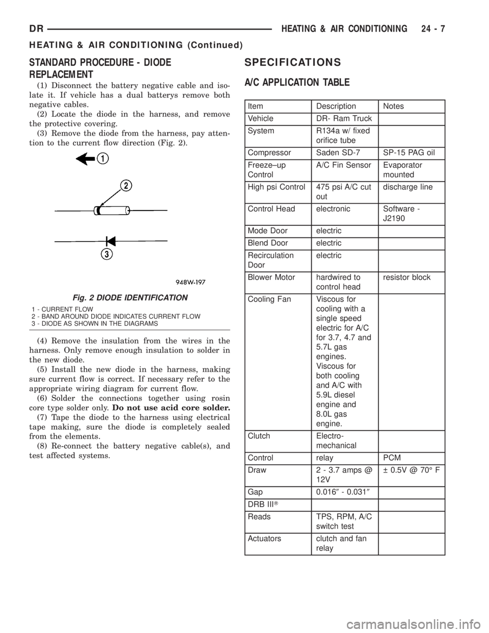
the protective covering.
(3) Remove the diode from the harness, pay atten-
tion to the current flow direction (Fig. 2).
(4) Remove the insulation from the wires in the
harness. Only remove enough insulation to solder in
the new diode.
(5) Install the new diode in the harness, making
sure current flow is correct. If necessary refer to the
appropriate wiring diagram for current flow.
(6) Solder the connections together using rosin
core type solder only.Do not use acid core solder.
(7) Tape the diode to the harness using electrical
tape making, sure the diode is completely sealed
from the elements.
(8) Re-connect the battery negative cable(s), and
test affected systems.
SPECIFICATIONS
A/C APPLICATION TABLE
Item Description Notes
Vehicle DR- Ram Truck
System R134a w/ fixed
orifice tube
Compressor Saden SD-7 SP-15 PAG oil
Freeze±up
ControlA/C Fin Sensor Evaporator
mounted
High psi Control 475 psi A/C cut
outdischarge line
Control Head electronic Software -
J2190
Mode Door electric
Blend Door electric
Recirculation
Doorelectric
Blower Motor hardwired to
control headresistor block
Cooling Fan Viscous for
cooling with a
single speed
electric for A/C
for 3.7, 4.7 and
5.7L gas
engines.
Viscous for
both cooling
and A/C with
5.9L diesel
engine and
8.0L gas
engine.
Clutch Electro-
mechanical
Control relay PCM
Draw 2 - 3.7 amps @
12V 0.5V @ 70É F
Gap 0.0169- 0.0319
DRB IIIT
Reads TPS, RPM, A/C
switch test
Actuators clutch and fan
relay
Fig. 2 DIODE IDENTIFICATION
1 - CURRENT FLOW
2 - BAND AROUND DIODE INDICATES CURRENT FLOW
3 - DIODE AS SHOWN IN THE DIAGRAMS
DRHEATING & AIR CONDITIONING 24 - 7
HEATING & AIR CONDITIONING (Continued)
Page 2785 of 2895
seconds. Refer to Electronic Control Modules for
more information on the JTEC controls.
DIAGNOSIS AND TESTING - A/C COMPRESSOR
CLUTCH COIL
For circuit descriptions and diagrams, (Refer to
Appropriate Wiring Information). The battery must
be fully-charged before performing the following
tests. Refer to Battery for more information.
(1) Connect an ammeter (0 to 10 ampere scale) in
series with the clutch coil terminal. Use a voltmeter
(0 to 20 volt scale) with clip-type leads for measuring
the voltage across the battery and the compressor
clutch coil.
(2) With the A/C Heater mode control switch in
any A/C mode, and the blower motor switch in the
lowest speed position, start the engine and run it at
normal idle.
(3) The compressor clutch coil voltage should read
within 0.2 volts of the battery voltage. If there is
voltage at the clutch coil, but the reading is not
within 0.2 volts of the battery voltage, test the clutch
coil feed circuit for excessive voltage drop and repair
as required. If there is no voltage reading at the
clutch coil, use a DRB IIItscan tool and (Refer to
Appropriate Diagnostic Information) for testing of the
compressor clutch circuit and PCM control. The fol-
lowing components must be checked and repaired as
required before you can complete testing of the clutch
coil:
²Fuses in the junction block and the Power Dis-
tribution Center (PDC)
²A/C heater mode control switch
²Compressor clutch relay
²A/C high pressure transducer switch²JTEC
(4) The compressor clutch coil is acceptable if the
current draw measured at the clutch coil is 2.0 to 3.9
amperes with the electrical system voltage at 11.5 to
12.5 volts. This should only be checked with the work
area temperature at 21É C (70É F). If system voltage
is more than 12.5 volts, add electrical loads by turn-
ing on electrical accessories until the system voltage
drops below 12.5 volts.
(a) If the clutch coil current reading is four
amperes or more, the coil is shorted and should be
replaced.
(b) If the clutch coil current reading is zero, the
coil is open and should be replaced.
STANDARD PROCEDURE - A/C COMPRESSOR
CLUTCH BREAK-IN
After a new compressor clutch has been installed,
cycle the compressor clutch approximately twenty
times (five seconds on, then five seconds off). During
this procedure, set the A/C Heater control to the
Recirculation Mode, the blower motor switch in the
highest speed position, and the engine speed at 1500
to 2000 rpm. This procedure (burnishing) will seat
the opposing friction surfaces and provide a higher
compressor clutch torque capability.
REMOVAL
The refrigerant system can remain fully-charged
during compressor clutch, rotor, or coil replacement.
The compressor clutch can be serviced in the vehicle.
(1) Disconnect and isolate the battery negative
cable.
(2) Remove the serpentine drive belt(Refer to 7 -
COOLING/ACCESSORY DRIVE/DRIVE BELTS -
REMOVAL).
(3) Unplug the compressor clutch coil wire harness
connector.
(4) Remove the bolts that secure the compressor to
the mounting bracket.
(5) Remove the compressor from the mounting
bracket. Support the compressor in the engine com-
partment while servicing the clutch.
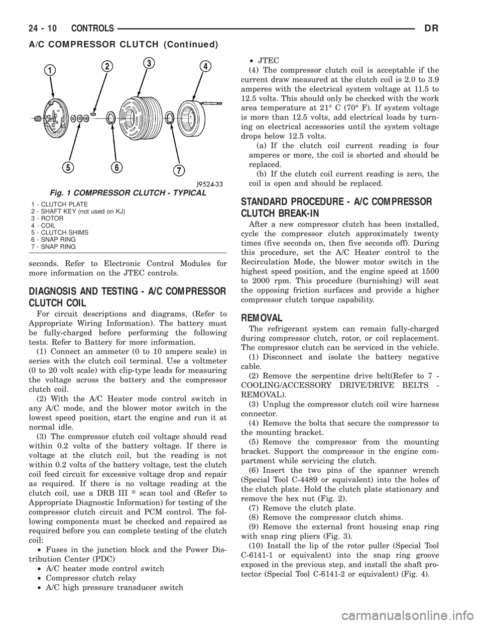
(6) Insert the two pins of the spanner wrench
(Special Tool C-4489 or equivalent) into the holes of
the clutch plate. Hold the clutch plate stationary and
remove the hex nut (Fig. 2).
(7) Remove the clutch plate.
(8) Remove the compressor clutch shims.
(9) Remove the external front housing snap ring
with snap ring pliers (Fig. 3).
(10)
Install the lip of the rotor puller (Special Tool
C-6141-1 or equivalent) into the snap ring groove
exposed in the previous step, and install the shaft pro-
tector (Special Tool C-6141-2 or equivalent) (Fig. 4).
Fig. 1 COMPRESSOR CLUTCH - TYPICAL
1 - CLUTCH PLATE
2 - SHAFT KEY (not used on KJ)
3 - ROTOR
4 - COIL
5 - CLUTCH SHIMS
6 - SNAP RING
7 - SNAP RING
24 - 10 CONTROLSDR
A/C COMPRESSOR CLUTCH (Continued)