2003 DODGE RAM electrical
[x] Cancel search: electricalPage 425 of 2895

²a faulty or improperly adjusted switch that
allows a lamp to stay on. Refer to Ignition-Off Draw
Test in 8, Battery for more information.
INSPECTION
The PCM (Powertrain Control Module), or ECM
(Diesel) monitors critical input and output circuits of
the charging system, making sure they are opera-
tional. A Diagnostic Trouble Code (DTC) is assigned
to each input and output circuit monitored by the
On-Board Diagnostic (OBD) system. Some charging
system circuits are checked continuously, and some
are checked only under certain conditions.
Refer to Diagnostic Trouble Codes in; Powertrain
Control Module; Electronic Control Modules for more
DTC information. This will include a complete list of
DTC's including DTC's for the charging system.
To perform a complete test of the charging system,
refer to the appropriate Powertrain Diagnostic Proce-
dures service manual and the DRBtscan tool. Per-
form the following inspections before attaching the
scan tool.
(1) Inspect the battery condition. Refer to 8, Bat-
tery for procedures.(2) Inspect condition of battery cable terminals,
battery posts, connections at engine block, starter
solenoid and relay. They should be clean and tight.
Repair as required.
(3) Inspect all fuses in both the fuseblock and
Power Distribution Center (PDC) for tightness in
receptacles. They should be properly installed and
tight. Repair or replace as required.
(4) Inspect generator mounting bolts for tightness.
Replace or tighten bolts if required. Refer to the Gen-
erator Removal/Installation section of this group for
torque specifications.
(5) Inspect generator drive belt condition and ten-
sion. Tighten or replace belt as required. Refer to
Belt Tension Specifications in 7, Cooling System.
(6) Inspect automatic belt tensioner (if equipped).
Refer to 7, Cooling System for information.
(7) Inspect generator electrical connections at gen-
erator field, battery output, and ground terminal (if
equipped). Also check generator ground wire connec-
tion at engine (if equipped). They should all be clean
and tight. Repair as required.
SPECIFICATIONS
GENERATOR RATINGS
TYPE PART NUMBER RATED SAE AMPS ENGINES
DENSO 56029700AA 136 3.7L / 4.7L
DENSO 56029701AA 136 5.9L Gas
BOSCH 56041120AC 136 3.7L / 4.7L
BOSCH 56028238AB 136 5.9L Gas
DENSO 56028560AA 136 8.0L
DENSO 56028696AA 136 5.7L Gas/5.9L Diesel
BOSCH 56028699AA 136 5.7L Gas/5.9L Diesel
SPECIFICATIONS - TORQUE - GENERATOR /
CHARGING SYSTEM
DESCRIPTION N´m Ft. Lbs. In. Lbs.
Generator Mounting Bolts - 5.7L 41 30 -
Generator Support Bracket
Bolt/Nuts - 5.7L41 30 -
Generator Mounting Bolts - 8.0L 41 30 -
Generator Upper Mounting Bolt -
5.9L Diesel Engine41 30 -
Generator Upper Mounting Bolt -
5.9L Gas Engine41 30 -
8F - 20 CHARGINGDR
CHARGING (Continued)
Page 426 of 2895

DESCRIPTION N´m Ft. Lbs. In. Lbs.
Generator Lower Pivot Bolt / Nut -
5.9L Gas Engine41 30 -
Generator Vertical Mounting Bolt -
3.7L / 4.7L Engines55 40 -
Generator (long) Horizontal
Mounting Bolt - 3.7L / 4.7L Engines55 40 -
Generator (short) Horizontal
Mounting Bolt - 3.7L / 4.7L Engines74 55 -
Generator B+ Output Cable
Terminal Nut12 - 108
BATTERY TEMPERATURE
SENSOR
DESCRIPTION
The Battery Temperature Sensor (BTS) is attached
to the battery tray located under the battery.
OPERATION
The BTS is used to determine the battery temper-
ature and control battery charging rate. This temper-
ature data, along with data from monitored line
voltage, is used by the PCM (ECM Diesel) to vary the
battery charging rate. System voltage will be higher
at colder temperatures and is gradually reduced at
warmer temperatures.
The PCM sends 5 volts to the sensor and is
grounded through the sensor return line. As temper-
ature increases, resistance in the sensor decreases
and the detection voltage at the PCM increases.
The BTS is also used for OBD II diagnostics. Cer-
tain faults and OBD II monitors are either enabled
or disabled, depending upon BTS input (for example,
disable purge and enable Leak Detection Pump
(LDP) and O2 sensor heater tests). Most OBD II
monitors are disabled below 20ÉF.
REMOVAL
The battery temperature sensor is located under
the vehicle battery and is attached (snapped into) a
mounting hole on battery tray (Fig. 1).
(1) Remove battery. Refer to 8, Battery for proce-
dures.
(2) Pry sensor straight up from battery tray
mounting hole to gain access to electrical connector
(Fig. 1).
(3) Disconnect sensor from engine wire harness
electrical connector.INSTALLATION
The battery temperature sensor is located under
the vehicle battery and is attached (snapped into) a
mounting hole on battery tray.
(1) Pull electrical connector up through mounting
hole in top of battery tray.
(2) Connect sensor.
(3) Snap sensor into battery tray.
(4) Install battery. Refer to 8, Battery for proce-
dures.
Fig. 1 BATTERY TEMPERATURE SENSOR
LOCATION
1 - BATTERY TEMP. SENSOR
2 - BATTERY
3 - SENSOR ELEC. CONNECT.
4 - BATTERY TRAY
DRCHARGING 8F - 21
CHARGING (Continued)
Page 427 of 2895
GENERATOR
DESCRIPTION
The generator is belt-driven by the engine using a
serpentine type drive belt. It is serviced only as a
complete assembly. If the generator fails for any rea-
son, the entire assembly must be replaced.
OPERATION
As the energized rotor begins to rotate within the
generator, the spinning magnetic field induces a cur-
rent into the windings of the stator coil. Once the
generator begins producing sufficient current, it also
provides the current needed to energize the rotor.
The stator winding connections deliver the induced
alternating current to 3 positive and 3 negative
diodes for rectification. From the diodes, rectified
direct current is delivered to the vehicle electrical
system through the generator battery terminal.
Although the generators appear the same exter-
nally, different generators with different output rat-
ings are used on this vehicle. Be certain that the
replacement generator has the same output rating
and part number as the original unit. Refer to Gen-
erator Ratings in the Specifications section at the
back of this group for amperage ratings and part
numbers.
Noise emitting from the generator may be caused
by: worn, loose or defective bearings; a loose or defec-
tive drive pulley; incorrect, worn, damaged or misad-
justed fan drive belt; loose mounting bolts; a
misaligned drive pulley or a defective stator or diode.
REMOVAL
3.7L / 4.7L
WARNING: DISCONNECT NEGATIVE CABLE FROM
BATTERY BEFORE REMOVING BATTERY OUTPUT
WIRE (B+ WIRE) FROM GENERATOR. FAILURE TO
DO SO CAN RESULT IN INJURY OR DAMAGE TO
ELECTRICAL SYSTEM.
(1) Disconnect negative battery cable at battery.
(2) Remove generator drive belt. Refer to 7, Cool-
ing System for procedure.
(3) Unsnap plastic insulator cap from B+ output
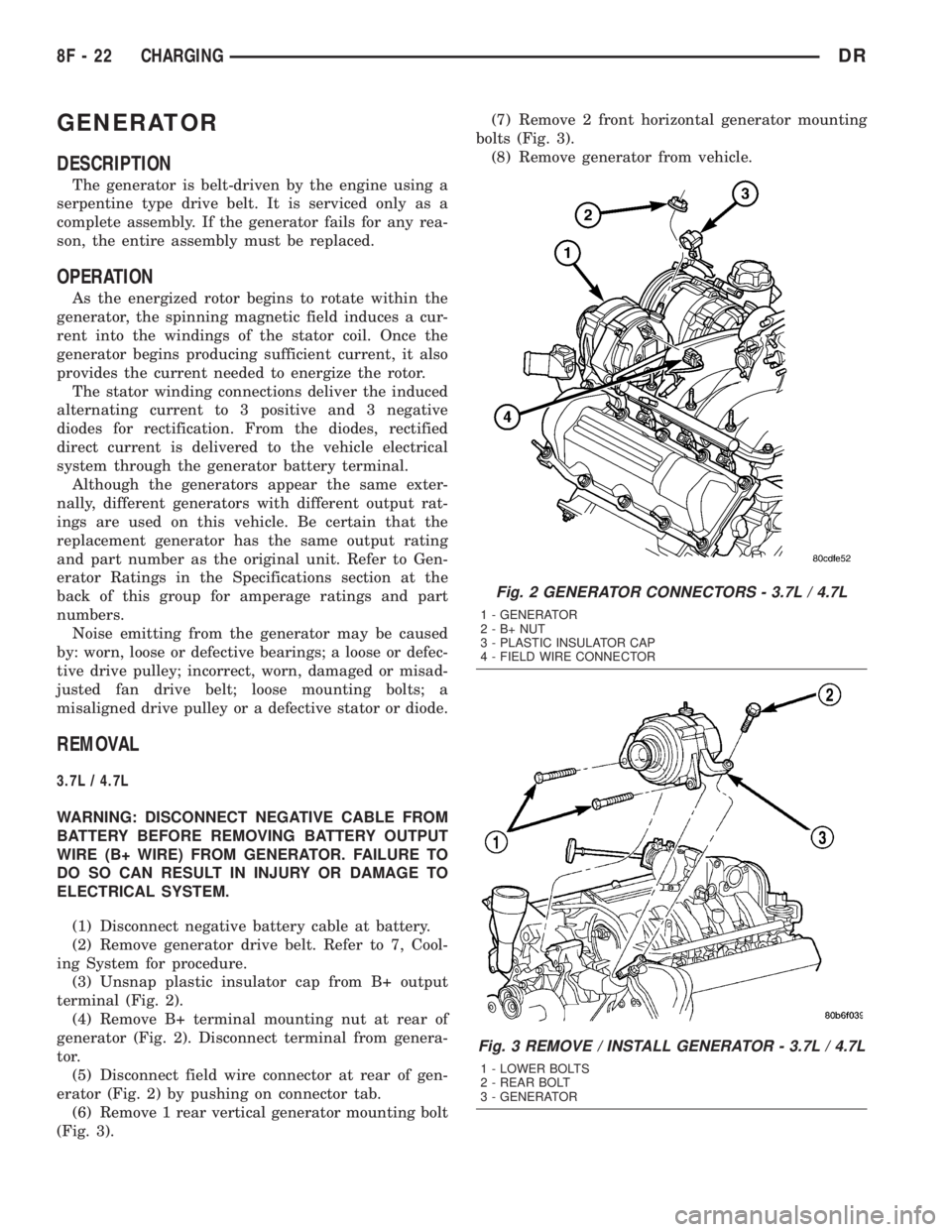
terminal (Fig. 2).
(4) Remove B+ terminal mounting nut at rear of
generator (Fig. 2). Disconnect terminal from genera-
tor.
(5) Disconnect field wire connector at rear of gen-
erator (Fig. 2) by pushing on connector tab.
(6) Remove 1 rear vertical generator mounting bolt
(Fig. 3).(7) Remove 2 front horizontal generator mounting
bolts (Fig. 3).
(8) Remove generator from vehicle.
Fig. 2 GENERATOR CONNECTORS - 3.7L / 4.7L
1 - GENERATOR
2-B+NUT
3 - PLASTIC INSULATOR CAP
4 - FIELD WIRE CONNECTOR
Fig. 3 REMOVE / INSTALL GENERATOR - 3.7L / 4.7L
1 - LOWER BOLTS
2 - REAR BOLT
3 - GENERATOR
8F - 22 CHARGINGDR
Page 428 of 2895
5.7L
WARNING: DISCONNECT NEGATIVE CABLE FROM
BATTERY BEFORE REMOVING BATTERY OUTPUT
WIRE (B+ WIRE) FROM GENERATOR. FAILURE TO
DO SO CAN RESULT IN INJURY OR DAMAGE TO
ELECTRICAL SYSTEM.
(1) Disconnect negative battery cable at battery.
(2) Remove generator drive belt. Refer to 7, Cool-
ing System for procedure.
(3) Unsnap plastic insulator cap from B+ output
terminal.
(4) Remove B+ terminal mounting nut at rear of
generator. Disconnect terminal from generator.
(5) Disconnect field wire connector at rear of gen-
erator by pushing on connector tab.
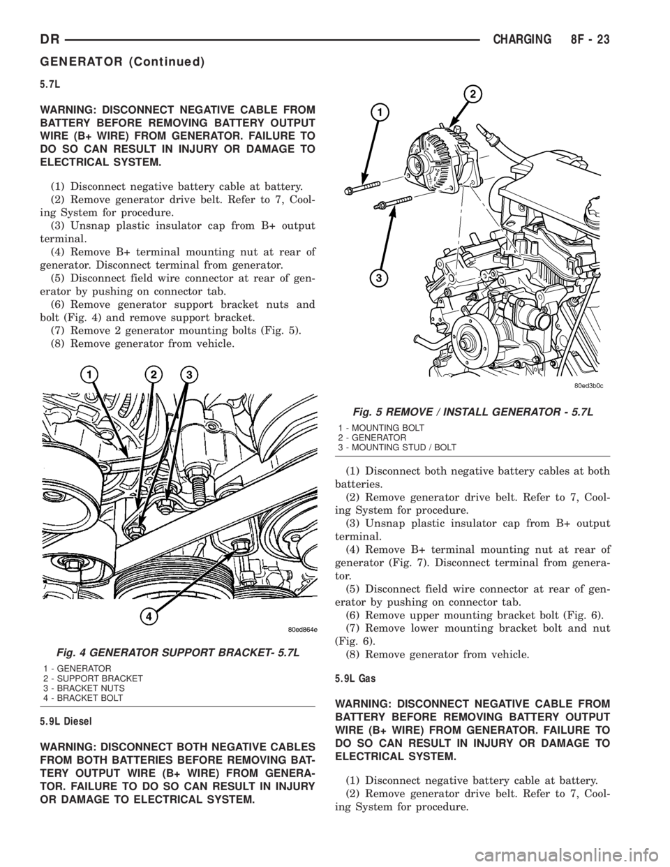
(6) Remove generator support bracket nuts and
bolt (Fig. 4) and remove support bracket.
(7) Remove 2 generator mounting bolts (Fig. 5).
(8) Remove generator from vehicle.
5.9L Diesel
WARNING: DISCONNECT BOTH NEGATIVE CABLES
FROM BOTH BATTERIES BEFORE REMOVING BAT-
TERY OUTPUT WIRE (B+ WIRE) FROM GENERA-
TOR. FAILURE TO DO SO CAN RESULT IN INJURY
OR DAMAGE TO ELECTRICAL SYSTEM.(1) Disconnect both negative battery cables at both
batteries.
(2) Remove generator drive belt. Refer to 7, Cool-
ing System for procedure.
(3) Unsnap plastic insulator cap from B+ output
terminal.
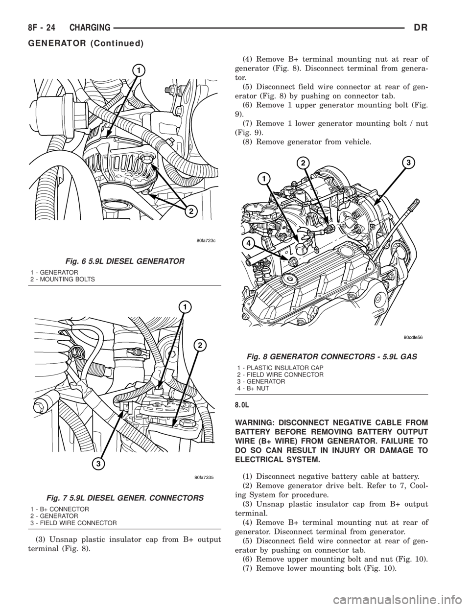
(4) Remove B+ terminal mounting nut at rear of
generator (Fig. 7). Disconnect terminal from genera-
tor.
(5) Disconnect field wire connector at rear of gen-
erator by pushing on connector tab.
(6) Remove upper mounting bracket bolt (Fig. 6).
(7) Remove lower mounting bracket bolt and nut
(Fig. 6).
(8) Remove generator from vehicle.
5.9L Gas
WARNING: DISCONNECT NEGATIVE CABLE FROM
BATTERY BEFORE REMOVING BATTERY OUTPUT
WIRE (B+ WIRE) FROM GENERATOR. FAILURE TO
DO SO CAN RESULT IN INJURY OR DAMAGE TO
ELECTRICAL SYSTEM.
(1) Disconnect negative battery cable at battery.
(2) Remove generator drive belt. Refer to 7, Cool-
ing System for procedure.
Fig. 4 GENERATOR SUPPORT BRACKET- 5.7L
1 - GENERATOR
2 - SUPPORT BRACKET
3 - BRACKET NUTS
4 - BRACKET BOLT
Fig. 5 REMOVE / INSTALL GENERATOR - 5.7L
1 - MOUNTING BOLT
2 - GENERATOR
3 - MOUNTING STUD / BOLT
DRCHARGING 8F - 23
GENERATOR (Continued)
Page 429 of 2895
(3) Unsnap plastic insulator cap from B+ output
terminal (Fig. 8).(4) Remove B+ terminal mounting nut at rear of
generator (Fig. 8). Disconnect terminal from genera-
tor.
(5) Disconnect field wire connector at rear of gen-
erator (Fig. 8) by pushing on connector tab.
(6) Remove 1 upper generator mounting bolt (Fig.
9).
(7) Remove 1 lower generator mounting bolt / nut
(Fig. 9).
(8) Remove generator from vehicle.
8.0L
WARNING: DISCONNECT NEGATIVE CABLE FROM
BATTERY BEFORE REMOVING BATTERY OUTPUT
WIRE (B+ WIRE) FROM GENERATOR. FAILURE TO
DO SO CAN RESULT IN INJURY OR DAMAGE TO
ELECTRICAL SYSTEM.
(1) Disconnect negative battery cable at battery.
(2) Remove generator drive belt. Refer to 7, Cool-
ing System for procedure.
(3) Unsnap plastic insulator cap from B+ output
terminal.
(4) Remove B+ terminal mounting nut at rear of
generator. Disconnect terminal from generator.
(5) Disconnect field wire connector at rear of gen-
erator by pushing on connector tab.
(6) Remove upper mounting bolt and nut (Fig. 10).
(7) Remove lower mounting bolt (Fig. 10).
Fig. 6 5.9L DIESEL GENERATOR
1 - GENERATOR
2 - MOUNTING BOLTS
Fig. 7 5.9L DIESEL GENER. CONNECTORS
1 - B+ CONNECTOR
2 - GENERATOR
3 - FIELD WIRE CONNECTOR
Fig. 8 GENERATOR CONNECTORS - 5.9L GAS
1 - PLASTIC INSULATOR CAP
2 - FIELD WIRE CONNECTOR
3 - GENERATOR
4-B+NUT
8F - 24 CHARGINGDR
GENERATOR (Continued)
Page 441 of 2895
(4) Move starter motor towards front of vehicle far
enough for nose of starter pinion housing to clear
housing. Always support starter motor during this
process. Do not let starter motor hang from wire har-
ness.
(5) Tilt nose downwards and lower starter motor
far enough to access and remove nuts securing
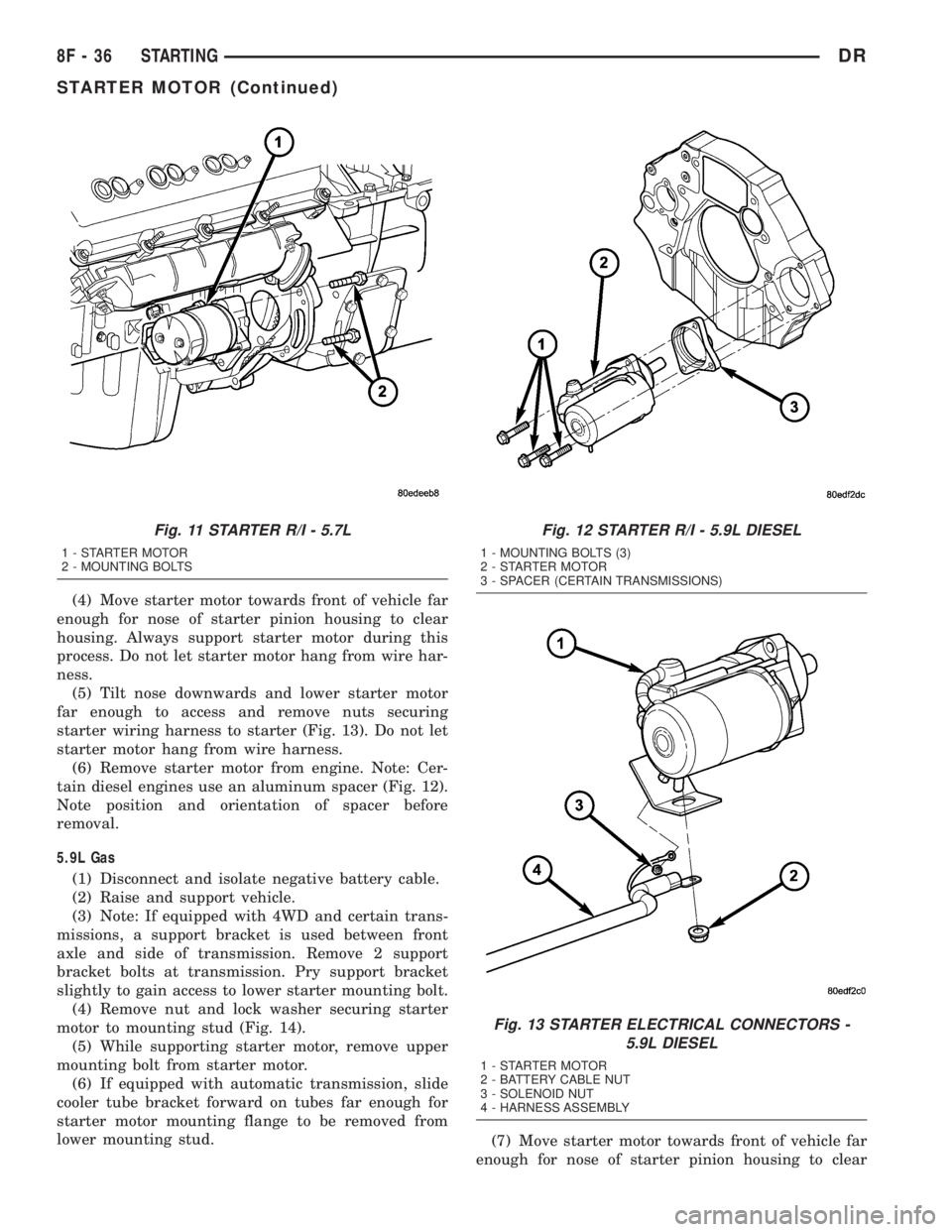
starter wiring harness to starter (Fig. 13). Do not let
starter motor hang from wire harness.
(6) Remove starter motor from engine. Note: Cer-
tain diesel engines use an aluminum spacer (Fig. 12).
Note position and orientation of spacer before
removal.
5.9L Gas
(1) Disconnect and isolate negative battery cable.
(2) Raise and support vehicle.
(3) Note: If equipped with 4WD and certain trans-
missions, a support bracket is used between front
axle and side of transmission. Remove 2 support
bracket bolts at transmission. Pry support bracket
slightly to gain access to lower starter mounting bolt.
(4) Remove nut and lock washer securing starter
motor to mounting stud (Fig. 14).
(5) While supporting starter motor, remove upper
mounting bolt from starter motor.
(6) If equipped with automatic transmission, slide
cooler tube bracket forward on tubes far enough for
starter motor mounting flange to be removed from
lower mounting stud.
(7) Move starter motor towards front of vehicle far
enough for nose of starter pinion housing to clear
Fig. 11 STARTER R/I - 5.7L
1 - STARTER MOTOR
2 - MOUNTING BOLTS
Fig. 12 STARTER R/I - 5.9L DIESEL
1 - MOUNTING BOLTS (3)
2 - STARTER MOTOR
3 - SPACER (CERTAIN TRANSMISSIONS)
Fig. 13 STARTER ELECTRICAL CONNECTORS -
5.9L DIESEL
1 - STARTER MOTOR
2 - BATTERY CABLE NUT
3 - SOLENOID NUT
4 - HARNESS ASSEMBLY
8F - 36 STARTINGDR
STARTER MOTOR (Continued)
Page 443 of 2895
STARTER MOTOR RELAY
DESCRIPTION
The starter relay is an electromechanical device
that switches battery current to the pull-in coil of the
starter solenoid when ignition switch is turned to
Start position. The starter relay is located in the
Power Distribution Center (PDC) in the engine com-
partment. See PDC cover for relay identification and
location.
The starter relay is a International Standards
Organization (ISO) relay. Relays conforming to ISO
specifications have common physical dimensions, cur-
rent capacities, terminal patterns, and terminal func-
tions.
The starter relay cannot be repaired or adjusted. If
faulty or damaged, it must be replaced.
OPERATION
The ISO relay consists of an electromagnetic coil, a
resistor or diode, and three (two fixed and one mov-
able) electrical contacts. The movable (common feed)
relay contact is held against one of the fixed contacts
(normally closed) by spring pressure. When electro-
magnetic coil is energized, it draws the movable con-
tact away from normally closed fixed contact, and
holds it against the other (normally open) fixed con-
tact.
When electromagnetic coil is de-energized, spring
pressure returns movable contact to normally closed
position. The resistor or diode is connected in parallel
with electromagnetic coil within relay, and helps to
dissipate voltage spikes produced when coil is de-en-
ergized.
DIAGNOSIS AND TESTING - STARTER RELAY
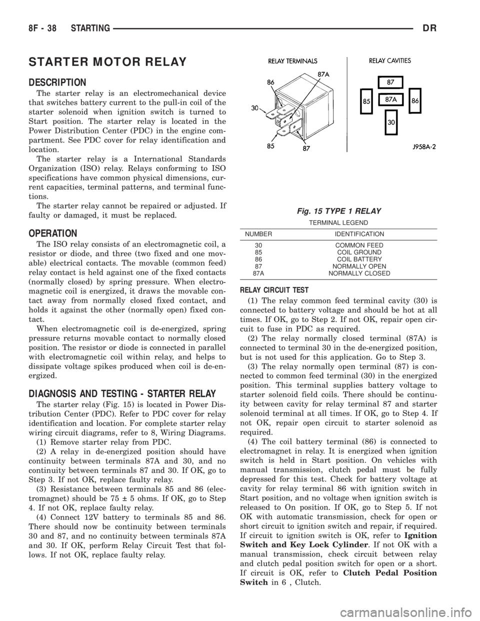
The starter relay (Fig. 15) is located in Power Dis-
tribution Center (PDC). Refer to PDC cover for relay
identification and location. For complete starter relay
wiring circuit diagrams, refer to 8, Wiring Diagrams.
(1) Remove starter relay from PDC.
(2) A relay in de-energized position should have
continuity between terminals 87A and 30, and no
continuity between terminals 87 and 30. If OK, go to
Step 3. If not OK, replace faulty relay.
(3) Resistance between terminals 85 and 86 (elec-
tromagnet) should be 75 5 ohms. If OK, go to Step
4. If not OK, replace faulty relay.
(4) Connect 12V battery to terminals 85 and 86.
There should now be continuity between terminals
30 and 87, and no continuity between terminals 87A
and 30. If OK, perform Relay Circuit Test that fol-
lows. If not OK, replace faulty relay.RELAY CIRCUIT TEST
(1) The relay common feed terminal cavity (30) is
connected to battery voltage and should be hot at all
times. If OK, go to Step 2. If not OK, repair open cir-
cuit to fuse in PDC as required.
(2) The relay normally closed terminal (87A) is
connected to terminal 30 in the de-energized position,
but is not used for this application. Go to Step 3.
(3) The relay normally open terminal (87) is con-
nected to common feed terminal (30) in the energized
position. This terminal supplies battery voltage to
starter solenoid field coils. There should be continu-
ity between cavity for relay terminal 87 and starter
solenoid terminal at all times. If OK, go to Step 4. If
not OK, repair open circuit to starter solenoid as
required.
(4) The coil battery terminal (86) is connected to
electromagnet in relay. It is energized when ignition
switch is held in Start position. On vehicles with
manual transmission, clutch pedal must be fully
depressed for this test. Check for battery voltage at
cavity for relay terminal 86 with ignition switch in
Start position, and no voltage when ignition switch is
released to On position. If OK, go to Step 5. If not
OK with automatic transmission, check for open or
short circuit to ignition switch and repair, if required.
If circuit to ignition switch is OK, refer toIgnition
Switch and Key Lock Cylinder. If not OK with a
manual transmission, check circuit between relay
and clutch pedal position switch for open or a short.
If circuit is OK, refer toClutch Pedal Position
Switchin 6 , Clutch.
Fig. 15 TYPE 1 RELAY
TERMINAL LEGEND
NUMBER IDENTIFICATION
30 COMMON FEED
85 COIL GROUND
86 COIL BATTERY
87 NORMALLY OPEN
87A NORMALLY CLOSED
8F - 38 STARTINGDR
Page 446 of 2895

HEATED SYSTEMS
TABLE OF CONTENTS
page page
HEATED MIRRORS......................... 1 HEATED SEATSYSTEM..................... 3
HEATED MIRRORS
TABLE OF CONTENTS
page page
HEATED MIRRORS
DESCRIPTION - HEATED MIRROR SYSTEM . . . 1
OPERATION - HEATED MIRROR SYSTEM.....1DIAGNOSIS AND TESTING - HEATED
MIRROR SYSTEM......................2
HEATED MIRRORS
DESCRIPTION - HEATED MIRROR SYSTEM
Electrically heated outside rear view mirrors are
an additional factory-installed option on models that
are equipped with factory-installed dual power mir-
rors. Vehicles with this option can be visually identi-
fied by the International Control and Display Symbol
icon for rear window defogger, which appears on thelower inboard corner of each outside mirror glass
(Fig. 1); or, by the heated mirror switch that is
located in the lower left corner of the a/c heater con-
trol unit face plate. The heated mirror system helps
the vehicle operator maintain outside rear view mir-
ror visibility during inclement operating conditions
by keeping both outside mirror glasses clear of ice,
snow, or fog. The heated mirror system for this vehi-
cle includes the following major components:
²The heated mirror switch, including the heated
mirror system solid state electronic control logic and
timer circuitry, the heated mirror relay and the
heated mirror system indicator lamp. All of these
components are integral to the a/c heater control unit
on the instrument panel.
²The two outside mirror heating grids, which are
integral to the power outside mirror units.
Following are general descriptions of the major
components in the heated mirror system. See the
owner's manual in the vehicle glove box for more
information on the features, use and operation of the
heated mirror system.
OPERATION - HEATED MIRROR SYSTEM
The solid state electronic control logic and timer
circuitry for the heated mirror system receives bat-
tery current from a fuse in the Junction Block (JB)
only when the ignition switch is in the On or Start
positions. After the heated mirror system is turned
On, the electronic control logic and timer circuitry
will automatically turn the system off after a pro-
grammed time interval of about fifteen minutes.
After the initial time interval has expired, if the
Fig. 1 HEATED MIRROR- typical
1 - POWER HEATED OUTSIDE REAR VIEW MIRROR
2 - REAR WINDOW DEFOGGER ICON
DRHEATED SYSTEMS 8G - 1