Page 396 of 1184

1F–298 ENGINE CONTROLS
DAEWOO M-150 BL2
Rough, Unstable, or Incorrect Idle, Stalling (Cont’d)
StepActionValue(s)YesNo
12
Is the long term fuel trim reading below the value
specified?
–20%
Go to
“Diagnostic Aids
for DTC P0172”
Go to Step 13
13
Is the long term fuel trim reading above the value
specified?
25%
Go to
“Diagnostic Aids
for DTC P0171”
–
14
1. Disconnect all of the fuel injector harness
connectors at the fuel injectors.
2. Connect an injector test light between the
harness terminals of each fuel injector connector.
3. Note the test light while cranking the engine.
Does the test light blink for all of the fuel injectors?
–
Go to Step 16Go to Step 15
15
1. Repair or replace the faulty injector drive circuit
harness, the connector, or the connector
terminals as needed.
2. If the harness, the connectors, and the terminals
are OK, replace the Engine Control Module
(ECM).
Is the repair complete?
–
System OK
–
16
Measure the resistance of each of the fuel injectors.
Is the resistance within the value specified (the
resistance will increase slightly at higher
temperatures)?
11.6–12.4 ΩGo to Step 18Go to Step 17
17
Replace any fuel injectors with a resistance that is
out of specifications.
Is the repair complete?
–
System OK
–
18Perform an injector diagnosis.
Is the problem found?–Go to Step 19Go to Step 20
19Replace any leaking or restricted fuel injectors.
Is the repair complete?–System OK–
20
1. With the engine OFF, disconnect the fuel
pressure regulator vacuum hose.
2. Thoroughly inspect the fuel pressure regulator
vacuum port and the fuel pressure regulator
vacuum hose for the presence of fuel.
Is the problem found?
–
Go to Step 21Go to Step 22
21Replace the fuel pressure regulator as needed.
Is the repair complete?–System OK–
22
1. Check the ignition system output voltage for all of
the cylinders using a spark tester.
2. Inspect the spark plugs for excessive wear,
insulation cracks, improper gap, or heavy
deposits.
3. Inspect the ignition wires for cracking, hardness,
or improper connections.
4. Replace any ignition wires with a resistance over
the value specified.
Is the problem found?
30000 ΩGo to Step 23Go to Step 24
23
Repair or replace any ignition system components
as needed.
Is the repair complete?
–
System OK
–
Page 398 of 1184

1F–300 ENGINE CONTROLS
DAEWOO M-150 BL2
EXCESSIVE EXHAUST EMISSIONS OR ODORS
Definition: A vehicle fails an emission test. The vehicle
has an excessive rotten egg smell. Excessive odors do
not necessarily indicate excessive emissions.
StepActionValue(s)YesNo
1
Were the Important Preliminary Checks performed?
–
Go to Step 2
Go to
“Important
Preliminary
Checks”
2
1. Run the engine until it reaches operating
temperature.
2. Perform an emission test.
Did the vehicle pass the emission test?
–
System OKGo to Step 3
3
1. Connect the scan tool to the Data Link Connector
(DLC).
2. Road test the vehicle.
3. Monitor the long term fuel trim memory.
Is the long term fuel trim memory within the value
specified?
–20 – 25 %Go to Step 6Go to Step 4
4
Is the long term fuel trim memory below the value
specified?
–20 %
Go to
“Diagnostic Aids
for DTC P0172”
Go to Step 5
5
Is the long term fuel trim memory above the value
specified?
25 %
Go to
“Diagnostic Aids
for DTC P0171”
–
6
1. Check for a properly installed fuel cap.
2. Check the fuel system pressure.
3. Perform an injector diagnosis.
Is the problem found?
–
Go to Step 7Go to Step 8
7
1. Repair or replace any fuel system components as
needed.
2. Perform an emission test.
Did the vehicle pass the emission test?
–
System OK
–
8
1. Check the ignition system for proper operation.
2. Inspect the spark plugs for excessive wear,
insulation cracks, improper gap, or heavy
deposits.
3. Check the ignition wires for cracking, hardness, or
improper connections.
Is the problem found?
–
Go to Step 9Go to Step 10
9
1. Repair or replace any ignition system components
as needed.
2. Perform an emission test.
Did the vehicle pass the emission test?
–
System OK
–
Page 402 of 1184
1F–304 ENGINE CONTROLS
DAEWOO M-150 BL2
REPAIR INSTRUCTIONS
ON-VEHICLE SERVICE
D102F502
D102F501
FUEL PUMP
Tools Required
DW 140–010A Fuel Pump Lock Ring Remover/Installer.
Removal Procedure
Caution: The fuel system is under pressure. To
avoid fuel spillage and the risk of personal injury or
fire, it is necessary to relieve the fuel system pres-
sure before disconnecting the fuel lines.
1. Relieve the fuel system pressure.
�Start the engine and remove the rear seat cushon
(1).
�Remove the fuel pump access cover (2).
�Disconnect the fuel pump assembly electrical con-
nector lock pin (3).
�Disconnect the fuel pump assembly electrical con-
nector (4).
�Crank the engine for an additional 10 seconds.
D102F503
2. Disconnect the fuel lines from the fuel pump.
�Disconnect the fuel outlet line (1).
�Disconnect the fuel tank return line (2).
Page 403 of 1184
ENGINE CONTROLS 1F–305
DAEWOO M-150 BL2
D12F504A
3. Remove the fuel pump assembly from the tank.
�Install the fuel pump lock ring remover/installer DW
140– 010A.
�Turn the fuel tank lock ring counterclockwise (1).
D102F505
�Remove the fuel pump assembly (2).
�Remove the fuel pump gasket (3).
D102F506
Installation Procedure
1. Install in the reverse order of removal.
2. Perform an operational check of the fuel pump.
�Perform an operational check of the ignition switch
ON the 2 seconds fuel pump operation.
D102F507
FUEL PRESSURE REGULATOR
Removal Procedure
Caution: The fuel system is under pressure. To
avoid fuel spillage and the risk of personal injury or
fire, it is necessary to relieve the fuel system pres-
sure before disconnecting the fuel lines.
1. Relieve the fuel system pressure after remove the
fuel pump assembly. Refer to “Fuel Pump” in this
section.
Page 404 of 1184

1F–306 ENGINE CONTROLS
DAEWOO M-150 BL2
D102F508
2. Remove the fuel pressure regulator from the fuel
pump.
�Remove the retainer from the fuel pump assembly
(1).
�Remove the fuel pressure regulator (2).
�Check the O–ring seals for the damage or the rip.
�Use a vacuum gauge to check the diaphram for
damage and the spring for operation.
D102F509
Installation Procedure
1. Install in the reverse order of removal.
�Do not reuse the removed O–ring seals. Replace
the removed O–ring seals with the new ones.
D102F511
D102F510
FUEL FILTER
Removal Procedure
Caution: The fuel system is under pressure. To
avoid fuel spillage and the risk of personal injury or
fire, it is necessary to relieve the fuel system pres-
sure before disconnecting the fuel lines.
1. Relieve the fuel system pressure.
Refer to “Fuel Pump” in this section.
2. Remove the fuel filter from the fuel tank.
�Disconnect the inlet/outlet fuel lines by pushing the
line connector lock and pulling off the hose of the
fuel filter tube (1).
�Remove the screw from the retaining clamp (2).
�Remove the fuel filter (3).
Page 405 of 1184

ENGINE CONTROLS 1F–307
DAEWOO M-150 BL2
D102F512
Installation Procedure
1. Install in the reverse order of removal.
�Install the new fuel filter into the retaining clamp.
Note the flow direction.
�Connect the inlet/outlet lines. Secure the lines with
the connector lock.
�Perform a leak test of the fuel filter.
D102F514
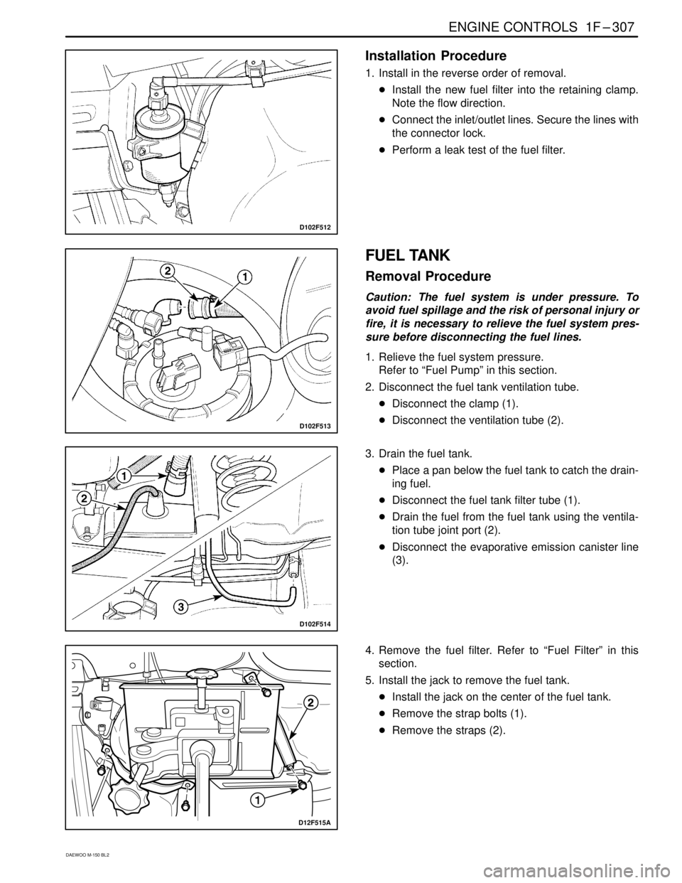
D102F513
FUEL TANK
Removal Procedure
Caution: The fuel system is under pressure. To
avoid fuel spillage and the risk of personal injury or
fire, it is necessary to relieve the fuel system pres-
sure before disconnecting the fuel lines.
1. Relieve the fuel system pressure.
Refer to “Fuel Pump” in this section.
2. Disconnect the fuel tank ventilation tube.
�Disconnect the clamp (1).
�Disconnect the ventilation tube (2).
3. Drain the fuel tank.
�Place a pan below the fuel tank to catch the drain-
ing fuel.
�Disconnect the fuel tank filter tube (1).
�Drain the fuel from the fuel tank using the ventila-
tion tube joint port (2).
�Disconnect the evaporative emission canister line
(3).
D12F515A
4. Remove the fuel filter. Refer to “Fuel Filter” in this
section.
5. Install the jack to remove the fuel tank.
�Install the jack on the center of the fuel tank.
�Remove the strap bolts (1).
�Remove the straps (2).
Page 406 of 1184

1F–308 ENGINE CONTROLS
DAEWOO M-150 BL2
D102F516
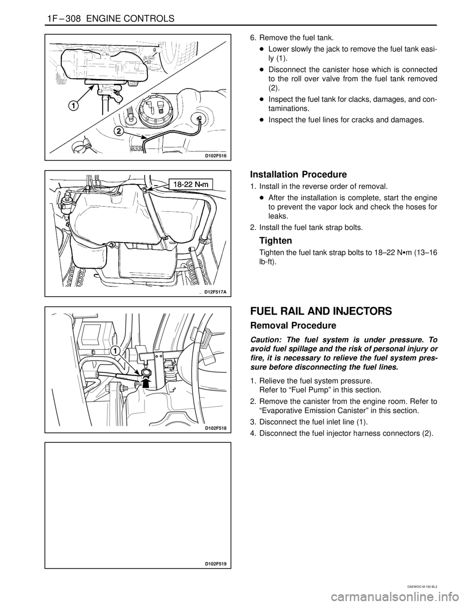
6. Remove the fuel tank.
�Lower slowly the jack to remove the fuel tank easi-
ly (1).
�Disconnect the canister hose which is connected
to the roll over valve from the fuel tank removed
(2).
�Inspect the fuel tank for clacks, damages, and con-
taminations.
�Inspect the fuel lines for cracks and damages.
D12F517A
Installation Procedure
1. Install in the reverse order of removal.
�After the installation is complete, start the engine
to prevent the vapor lock and check the hoses for
leaks.
2. Install the fuel tank strap bolts.
Tighten
Tighten the fuel tank strap bolts to 18–22 N�m (13–16
lb-ft).
D102F519
D102F518
FUEL RAIL AND INJECTORS
Removal Procedure
Caution: The fuel system is under pressure. To
avoid fuel spillage and the risk of personal injury or
fire, it is necessary to relieve the fuel system pres-
sure before disconnecting the fuel lines.
1. Relieve the fuel system pressure.
Refer to “Fuel Pump” in this section.
2. Remove the canister from the engine room. Refer to
“Evaporative Emission Canister” in this section.
3. Disconnect the fuel inlet line (1).
4. Disconnect the fuel injector harness connectors (2).
Page 417 of 1184
ENGINE CONTROLS 1F–319
DAEWOO M-150 BL2
SPECIFICATIONS
FASTENER TIGHTENING SPECIFICATIONS
ApplicationN�mLb-FtLb-In
Camshaft Position Sensor Bolts10–14–89–124
Engine Coolant Temperature (ECT) Sensor8–12–71–106
Crankshaft Position (CKP) Sensor Retaining Bolt5–8–44–71
Electronic Ignition (EI) System Ignition Coil Retaining
Bolts8–12–71–106
Evaporative Emission Canister Protective Cover8–71
Electric Exhaust Gas Recirculation (EEGR) Valve
Retaining Bolts20–3015–22–
Fuel Rail Retaining Bolts18–2213–16–
Fuel Tank Strap Retaining Nuts18–2213–16–
Knock Sensor Bolt15–2511–18–
Intake Air Temperature (IAT) Sensor20–3015–22–
Manifold Absolute Pressure (MAP) Sensor Retaining
Bolt8–12–71–106
Oxygen Sensor35–4426–33–
Heated Oxygen Sensor35–4426–33–
Throttle Body Retaining Bolt9–12–80–106
ECM Mounting Bolts6–8–53–71
SPECIAL TOOLS
SPECIAL TOOLS TABLE
D102F101
Scan Tool
D12F102A
DW–140–010A
Fuel Pump Lock Ring
Remover/Installer