Page 1105 of 1184
DOORS 9P–13
DAEWOO M-150 BL2
D19C580A
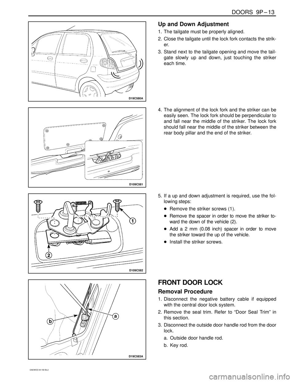
Up and Down Adjustment
1. The tailgate must be properly aligned.
2. Close the tailgate until the lock fork contacts the strik-
er.
3. Stand next to the tailgate opening and move the tail-
gate slowly up and down, just touching the striker
each time.
D109C581
4. The alignment of the lock fork and the striker can be
easily seen. The lock fork should be perpendicular to
and fall near the middle of the striker. The lock fork
should fall near the middle of the striker between the
rear body pillar and the end of the striker.
D109C582
5. If a up and down adjustment is required, use the fol-
lowing steps:
�Remove the striker screws (1).
�Remove the spacer in order to move the striker to-
ward the down of the vehicle (2).
�Add a 2 mm (0.08 inch) spacer in order to move
the striker toward the up of the vehicle.
�Install the striker screws.
D19C583A
FRONT DOOR LOCK
Removal Procedure
1. Disconnect the negative battery cable if equipped
with the central door lock system.
2. Remove the seal trim. Refer to “Door Seal Trim” in
this section.
3. Disconnect the outside door handle rod from the door
lock.
a. Outside door handle rod.
b. Key rod.
Page 1143 of 1184
BODY FRONT END 9R–9
DAEWOO M-150 BL2
D109C538
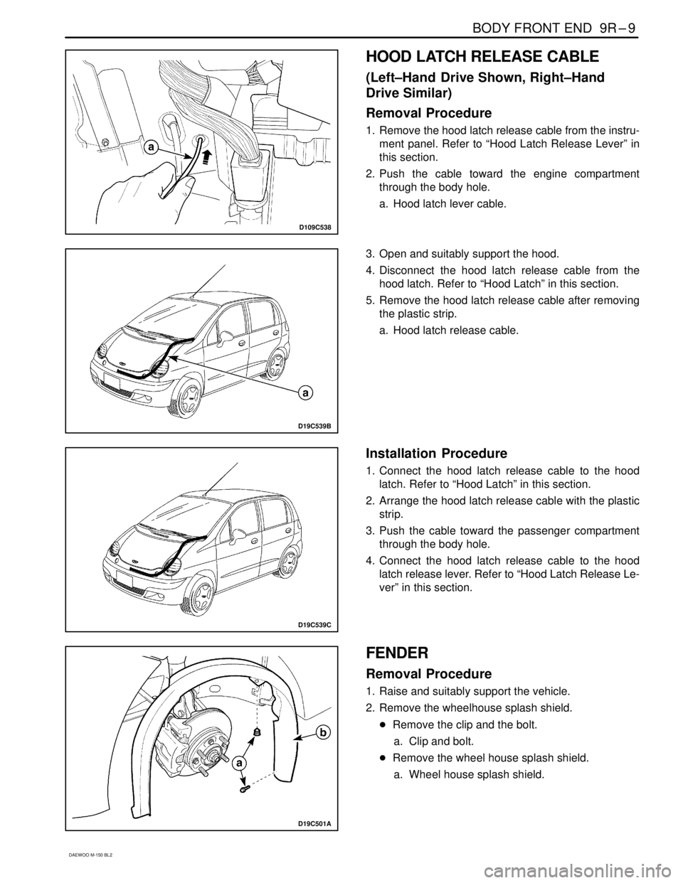
HOOD LATCH RELEASE CABLE
(Left–Hand Drive Shown, Right–Hand
Drive Similar)
Removal Procedure
1. Remove the hood latch release cable from the instru-
ment panel. Refer to “Hood Latch Release Lever” in
this section.
2. Push the cable toward the engine compartment
through the body hole.
a. Hood latch lever cable.
D19C539B
3. Open and suitably support the hood.
4. Disconnect the hood latch release cable from the
hood latch. Refer to “Hood Latch” in this section.
5. Remove the hood latch release cable after removing
the plastic strip.
a. Hood latch release cable.
D19C539C
Installation Procedure
1. Connect the hood latch release cable to the hood
latch. Refer to “Hood Latch” in this section.
2. Arrange the hood latch release cable with the plastic
strip.
3. Push the cable toward the passenger compartment
through the body hole.
4. Connect the hood latch release cable to the hood
latch release lever. Refer to “Hood Latch Release Le-
ver” in this section.
D19C501A
FENDER
Removal Procedure
1. Raise and suitably support the vehicle.
2. Remove the wheelhouse splash shield.
�Remove the clip and the bolt.
a. Clip and bolt.
�Remove the wheel house splash shield.
a. Wheel house splash shield.
Page 1180 of 1184
9T–28 IMMOBILIZER ANTI-THEFT SYSTEM
DAEWOO M–150 BL2
D29T002
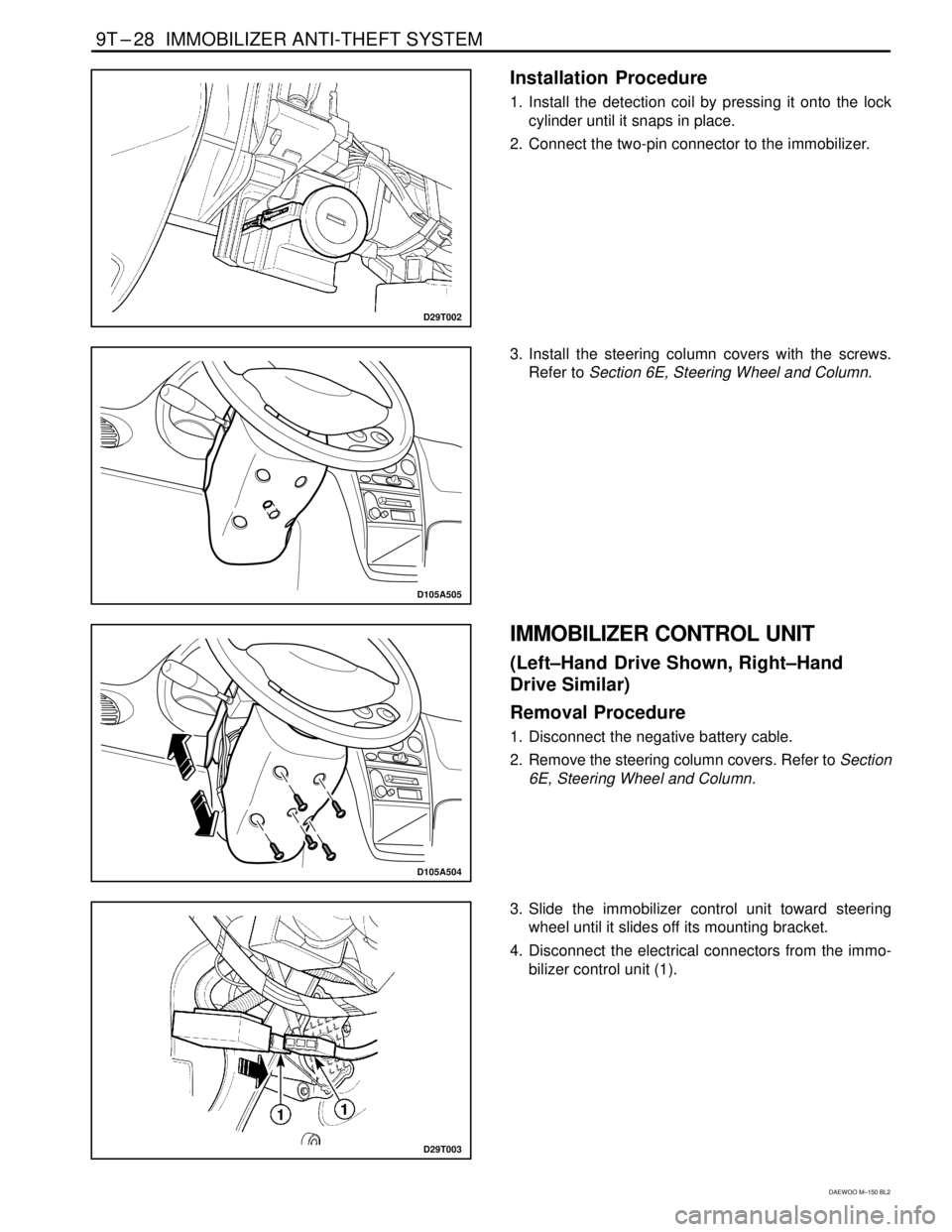
Installation Procedure
1. Install the detection coil by pressing it onto the lock
cylinder until it snaps in place.
2. Connect the two-pin connector to the immobilizer.
D105A505
3. Install the steering column covers with the screws.
Refer to Section 6E, Steering Wheel and Column.
D105A504
IMMOBILIZER CONTROL UNIT
(Left–Hand Drive Shown, Right–Hand
Drive Similar)
Removal Procedure
1. Disconnect the negative battery cable.
2. Remove the steering column covers. Refer to Section
6E, Steering Wheel and Column.
D29T003
3. Slide the immobilizer control unit toward steering
wheel until it slides off its mounting bracket.
4. Disconnect the electrical connectors from the immo-
bilizer control unit (1).