Page 966 of 1184
9D –8 WIPERS/WASHER SYSTEMS
DAEWOO M-150 BL2
D109D526
Installation Procedure
1. Install the wiper motor to the engine room with the
bolts.
a. Wiper motor assembly bolt.
2. Connect the electrical connector.
D109D527
3. Install the wiper linkage to the wiper motor linkage
ball.
b. Wiper linkage ball.
D109D528
4. Install the cowl vent grille. Refer to Section 9R, Body
Front End.
5. Install the windshield wiper arm. Refer to “Windshield
Wiper Arm” in this section.
6. Connect the negative battery cable.
D19D529A
REAR WINDOW WIPER MOTOR
Removal Procedure
1. Disconnect the negative battery cable.
2. Remove the wiper arm from the tailgate. Refer to
“Windshield Wiper Arm” in this section.
3. Remove the tailgate inside trim. Refer to Section 9G,
Interior Trim.
4. Remove the rear wiper motor assembly.
�Disconnect the electrical connector (1).
�Remove the screws (2).
�Remove the rear wiper motor assembly (3).
Page 970 of 1184
9D –12 WIPERS/WASHER SYSTEMS
DAEWOO M-150 BL2
D109D539
Installation Procedure
1. Install the wiper motor to the washer reservoir assem-
bly.
2. Install the washer reservoir assembly.
Refer to “Washer Reservoir” in this section.
3. Connect the negative battery cable.
4. Fill the washer reservoir.
D109D541
WINDSHIELD WASHER NOZZLE
Removal Procedure
1. Remove the cowl vent grille. Refer to Section 9R,
Body Front End.
2. Remove the washer nozzle from the cowl vent grille.
�Disconnect the washer nozzle hose (1).
�Remove the washer nozzle (2).
D109D542
Installation Procedure
1. Install the washer nozzle to the cowl vent grille.
2. Install the washer nozzle hose to the washer nozzle.
3. Install the cowl vent grille. Refer toSec-
tion 9R, Body Front End.
D109D543
REAR WINDOW WASHER NOZZLE
Removal Procedure
1. Remove the washer nozzle from the wiper arm.
�Disconnect the washer nozzle hose (1).
�Remove the washer nozzle (2).
Page 974 of 1184
9D –16 WIPERS/WASHER SYSTEMS
DAEWOO M-150 BL2
SCHEMATIC AND ROUTING DIAGRAMS
WINDSHIELD/REAR WINDOW WIPER AND WASHER SYSTEM
D19D208B
Page 976 of 1184

9E–2 INSTRUMENTATION/DRIVER INFORMATION
DAEWOO M-150 BL2
DESCRIPTION AND OPERATION
CIGAR LIGHTER
The cigar lighter is located in the front portion of the in-
strument panel. To use the lighter, push it in completely.
When the lighter is hot, it will release itself from contact
with the heating element. The lighter and the heating
element can be damaged if the lighter is not allowed to
release itself fully from the heating element. Cigar lighter
is not equipped with the lamp.
ASHTRAY
The ashtray is located in the lower portion of the instru-
ment panel. In case of cleaning the ashtray up, remove
the ashtray by pushing the upper button and clean it up.
The ashtray lamp is optional.
INSTRUMENT PANEL VENTS
The center and the side vents in the instrument panel
can be adjusted up and down and from side to side. The
side vents can also be aimed toward the side windows in
order to defog them.
GLOVE BOX
The glove box can be opened by pulling up on the latch
handle. The glove box must be removed in order to gain
access to the passenger-side airbag module.
DIGITAL CLOCK
The digital clock is located in the instrument panel, be-
low the defroster grille. The clock is capable of a 12 –
hour display.
INSTRUMENT CLUSTER
The instrument cluster is located above the steering col-
umn and in the instrument cluster trim panel. The instru-
ment cluster contains the instruments that provide the
driver with vehicle performance information. The instru-
ment cluster contains a speedometer, an odometer, a
trip odometer, a temperature gauge, a fuel gauge, and
several indicator lamps. For replacement of the indicator
lamp bulbs contained in the instrument cluster, refer to
“Instrument Cluster Indicator Lamps Specifications” in
this section.
SPEEDOMETER/ODOMETER/TRIP
ODOMETER
The speedometer measures the speed of the vehicle. It
consists of an instrument cluster gauge connected to
the vehicle speed sensor on the transaxle output shaft.
The odometer measures the total distance the vehicle
has traveled since it was manufactured. It consists of an
instrument cluster gauge connected to the vehicle
speed sensor on the transaxle output shaft.
The trip odometer measures the distance the vehicle
has traveled since the odometer was last reset. It con-
sists of an instrument cluster gauge connected to the
vehicle speed sensor on the transaxle output shaft. The
trip odometer can be reset to zero at any time so that the
driver can record the distance traveled from any starting
point.
FUEL GAUGE
The fuel gauge consists of an instrument cluster gauge
connected to a sending unit in the fuel tank.
The fuel gauge indicates the quantity of fuel in the tank
without the ignition switch position.
TEMPERATURE GAUGE
The temperature gauge consists of an instrument clus-
ter gauge connected to a temperature sensor that is in
contact with the circulating engine coolant.
The temperature gauge indicates the temperature of the
coolant. Prolonged driving or idling in very hot weather
may cause the pointer to move beyond the center of the
gauge. The engine is overheating if the pointer moves
into the red zone at the upper limit of the gauge.
INSTRUMENT CLUSTER INDICATOR
LAMPS
The instrument cluster contains indicator lamps that in-
dicate the functioning of certain systems or the exis-
tence of potential problems with the operation of the
vehicle. The indicator lamps are replaceable. For re-
placement of the indicator lamps contained in the instru-
ment cluster, refer to “Instrument Cluster Indicator
Lamps Specifications” in this section.
Page 978 of 1184
9E–4 INSTRUMENTATION/DRIVER INFORMATION
DAEWOO M-150 BL2
INSTRUMENT CLUSTER
D109B404
1. Instrument Cluster Lens
2. Instrument Cluster Window Plate
3. Speedometer Gauge
4. Fuel Gauge5. Temperature Gauge
6. Instrument Cluster Case
7. Fronted Circuit Plate
8. Instrument Cluster Bulb
Page 993 of 1184

INSTRUMENT/DRIVER INFORMATION 9E–19
DAEWOO M-150 BL2
D19B710A
7. Install the passenger’s airbag module blank cover to
the instrument panel with the screws.
Tighten
Tighten the screws to 1.5–2 N.m (13–18 lb-in).
a. Passenger’s airbag module blank cover screw
8. Install the instrument cluster brackets to the instru-
ment panel with the screws.
9. Install the instrument panel assembly. Refer to “In-
strument Panel” in this section.
10. Connect the negative battery cable.
D109B711
INSTRUMENT CLUSTER INDICATOR
LAMPS
Removal Procedure
1. Disconnect the negative battery cable.
2. Remove the instrument cluster from the instrument
panel. Refer to “Instrument Cluster” in this section.
3. Remove the indicator bulbs from the rear of the clus-
ter.
D109B712
Installation Procedure
1. Install the indicator bulb.
2. Install the instrument cluster to the instrument panel.
Refer to “Instrument Cluster” in this section.
3. Connect the negative battery cable.
D109B713
SPEEDOMETER/ODOMETER/TRIP
ODOMETER
Removal Procedure
1. Disconnect the negative battery cable.
2. Remove the instrument cluster from the instrument
panel. Refer to “Instrument Cluster” in this section.
3. Remove the instrument cluster lens and the face
plate.
a. Window plate.
Page 994 of 1184
9E –20 INSTRUMENT/DRIVER INFORMATION
DAEWOO M-150 BL2
D109B714
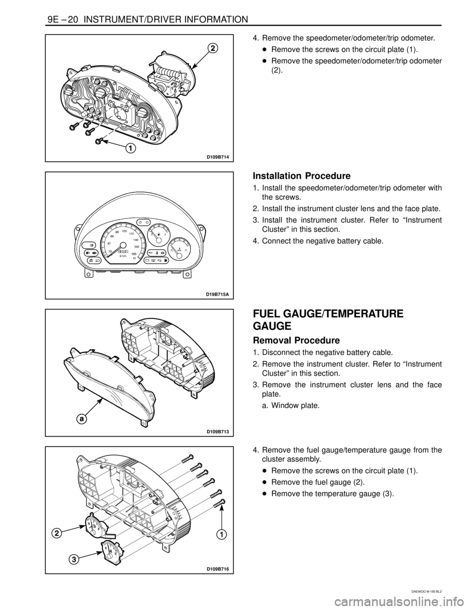
4. Remove the speedometer/odometer/trip odometer.
�Remove the screws on the circuit plate (1).
�Remove the speedometer/odometer/trip odometer
(2).
D19B715A
Installation Procedure
1. Install the speedometer/odometer/trip odometer with
the screws.
2. Install the instrument cluster lens and the face plate.
3. Install the instrument cluster. Refer to “Instrument
Cluster” in this section.
4. Connect the negative battery cable.
D109B713
FUEL GAUGE/TEMPERATURE
GAUGE
Removal Procedure
1. Disconnect the negative battery cable.
2. Remove the instrument cluster. Refer to “Instrument
Cluster” in this section.
3. Remove the instrument cluster lens and the face
plate.
a. Window plate.
D109B716
4. Remove the fuel gauge/temperature gauge from the
cluster assembly.
�Remove the screws on the circuit plate (1).
�Remove the fuel gauge (2).
�Remove the temperature gauge (3).
Page 1014 of 1184

9G –2 INTERIOR TRIM
DAEWOO M-150 BL2
DESCRIPTION AND OPERATION
INTERIOR TRIM PANELS
The interior trim panels are molded plastic and fasten
with screws or plastic clips.
PRESSURE RELIEF VENT
When all the windows are closed and the ventilation sys-
tem is on, the addition of outside air to the interior of the
vehicle causes a positive pressure within the vehicle. In
order to relieve the pressure, air is released through one
pressure relief vents. The pressure relief vent is located
in the luggage compartment, behind the spare wheel.
FLOOR CONSOLE
The floor console fits over the tunnel in the floor of the
vehicle and extends from under the center of the instru-
ment panel to the front seat area. The floor console con-
tains the transaxle shift lever and a cupholder.
The sensing and diagnosis module (SDM) for the airbag
system is located under the floor console.
PARKING BRAKE CABLE COVER
The parking brake cable cover should be removed to ad-
just the free play of the parking brake cable.
FLOOR CARPET
The molded one-piece floor carpet goes over both the
front and the rear floor pans.