Page 642 of 1184
FIVE-SPEED MANUAL TRANSAXLE 5B–17
DAEWOO M-150 BL2
D103B522
4. Remove the select lever.
�Remove the bolts (1).
�Remove the select lever (2).
D103B523
5. Remove the shift interlock bolt.
Important: Certainly remove the shift interlock bolt.
Otherwise, the gear shift control case can not be re-
moved.
D103B524
6. Remove the gear shift control case assembly.
�Remove the bolts (1).
Important: Make sure the gear shift lever is in NEU-
TRAL.
�Remove the gear shift control case assembly (2).
�Remove the gasket (3).
D103B525
7. Remove the shift lever.
�Position the gear shift control case assembly to the
vice with a protector.
�Remove the lever pin with a pin punch and a ham-
mer (1).
�Remove the shift lever (2).
�Remove the boot (3).
Page 704 of 1184

DAEWOO M-150 BL2
SECTION 6C
POWER STEERING GEAR
CAUTION: Disconnect the negative battery cable before removing or installing any electrical unit or when a
tool or equipment could easily come in contact with exposed electrical terminals. Disconnecting this cable
will help prevent personal injury and damage to the vehicle. The ignition must also be in B unless otherwise
noted.
TABLE OF CONTENTS
Description and Operation 6C-2. . . . . . . . . . . . . . . . . .
Power Rack and Pinion 6C-2. . . . . . . . . . . . . . . . . . . .
Diagnostic Information and Procedures 6C-3. . . . .
Power Rack and Pinion Steering Gear 6C-3. . . . . . .
Adjust the Free Load of the Steering Gear 6C-5. . .
Repair Instructions 6C-6. . . . . . . . . . . . . . . . . . . . . . . . .
On-Vehicle Service 6C-6. . . . . . . . . . . . . . . . . . . . . . . . . .
Rack and Pinion Assembly 6C-6. . . . . . . . . . . . . . . . .
Power Steering Gear Rack and Pinion Boot 6C-7. . . Unit Repair 6C-8. . . . . . . . . . . . . . . . . . . . . . . . . . . . . . . . .
Tie Rod End Boot 6C-8. . . . . . . . . . . . . . . . . . . . . . . . .
Hydraulic Cylinder Lines 6C-8. . . . . . . . . . . . . . . . . . . .
Rack and Pinion Steering Gear 6C-9. . . . . . . . . . . . . .
Assembly
Specifications 6C-13. . . . . . . . . . . . . . . . . . . . . . . . . . . .
General Specifications 6C-13. . . . . . . . . . . . . . . . . . . .
Fastener Tightening Specifications 6C-13. . . . . . . . . .
Page 710 of 1184
.
D15C537A
Installation Procedure
1. Install in the reverse order of removal.
2. Install the power steering gear bracket")
POWER STEERING GEAR 6C–7
DAEWOO M-150 BL2
D105C536
6. Remove the packing (5).
D15C537A
Installation Procedure
1. Install in the reverse order of removal.
2. Install the power steering gear bracket with the bolt.
Tighten
Tighten the bracket bolts to 50–55 N�m (36–41 lb-ft).
D15C512A
21–35 N�m21–35 N�m3. Connect the steering pipe. Refer to Section 6A, Pow-
er Steering System.
Tighten
Tighten the power steering pressure line fitting (1) to
21–35 N�m (16–25 lb-ft) (1).
Tighten the return line fitting to 21–35 N�m (16–25 lb-
ft) (2).
Important: When adding fluid or making a complete
fluid change, always use DEXRON� II or III power
steering fluid. Failure to use the proper fluid will cause
hose and seal change and fluid leaks.
4. Fill the fluid reservoir with power steering fluid.
5. Inspect for leaks. If there are leaks, correct the cause
of the leaks and bleed the system. Refer to Section
6A, Power Steering System.
POWER STEERING GEAR RACK
AND PINION BOOT
Refer to Section 6D, Manual Steering Gear.
Page 711 of 1184
6C –8 POWER STEERING GEAR
DAEWOO M-150 BL2
UNIT REPAIR
TIE ROD END BOOT
Refer to Section 6D, Manual Steering Gear.
D105C701
HYDRAULIC CYLINDER LINES
(Left–Hand Drive Shown, Right–Hand
Drive Similar)
Disassembly Procedure
1. Remove the rack and pinion steering assembly from
the vehicle. Refer to “Rack and Pinion Assembly” in
this section.
2. Disconnect the cylinder lines from the rack and pinion
housing.
�Remove the fitting (1).
�Remove the fitting (2).
D15C715A
Assembly Procedure
1. Connect the cylinder lines to the rack and pinion
housing.
2. Install the power steering line fittings at the pinion
valve end.
Tighten
Tighten the power steering line fittings to 25–35 N�m
(18–25 lb-ft) (1).
3. Install the power steering line fittings at the cylinder
end.
Tighten
Tighten the power steering line fittings to 25–35 N�m
(18–25 lb-ft) (2).
4. Install the rack and pinion steering assembly to the
vehicle. Refer to “Rack and Pinion Assembly” in this
section.
Page 713 of 1184
6C –10 POWER STEERING GEAR
DAEWOO M-150 BL2
D105C706
Important: Hit the drift using a hammer when the lower
pinion is vertical with the drift.
�Remove the bearing by hitting the bearing with the
flated drift and rubber hammer (6).
D105C707
�Remove the pinion shaft seal (7).
�Remove the needle bearing (8).
�Remove the retaining ring (9).
Important: The power steering gear housing and the
rack gear in this vehicle is not serviceable as unit.
The faulty parts must be replaced as whole units.
D105C708
Inspection Procedure
1. Inspect the tie rod ends and the ball joints for dam-
age. Refer to Section 6D, Manual Steering Gear.
2. Inspect the tie rod ends and the rack/pinion boot for
cracks or abnormal wear. Refer to Section 6D, Manu-
al Steering Gear.
3. Inspect the metal part for damage.
�Inspect the pinion gear for damage or wear (1).
D105C709
�Inspect the rack gear for damage or wear (2).
�Inspect the steering gear housing for damage or
wear(3).
Page 717 of 1184

DAEWOO M-150 BL2
SECTION 6D
MANUAL STEERING GEAR
CAUTION: Disconnect the negative battery cable before removing or installing any electrical unit or when a
tool or equipment could easily come in contact with exposed electrical terminals. Disconnecting this cable
will help prevent personal injury and damage to the vehicle. The ignition must also be in B unless otherwise
noted.
TABLE OF CONTENTS
Description and Operation 6D-2. . . . . . . . . . . . . . . . . .
Manual Rack and Pinion 6D-2. . . . . . . . . . . . . . . . . . . .
Component Locator 6D-3. . . . . . . . . . . . . . . . . . . . . . . .
Manual Rack and Pinion Steering Gear 6D-3. . . . . . .
Diagnostic Information and Procedures 6D-4. . . . .
Manual Rack and Pinion Steering Gear 6D-4. . . . . . .
Straight-Ahead Check 6D-5. . . . . . . . . . . . . . . . . . . . . .
Steering Wheel Restoration 6D-6. . . . . . . . . . . . . . . . .
Check The Turning Resistance of the
Tie Rod End or Tie Rod 6D-6. . . . . . . . . . . . . . . . . . . .
Adjust the Free Load of the Steering Gear 6D-6. . . .
Repair Instructions 6D-7. . . . . . . . . . . . . . . . . . . . . . . . . On-Vehicle Service 6D-7. . . . . . . . . . . . . . . . . . . . . . . . . .
Tie Rod End 6D-7. . . . . . . . . . . . . . . . . . . . . . . . . . . . . .
Rack and Pinion Boot 6D-8. . . . . . . . . . . . . . . . . . . . . .
Rack and Pinion Steering Gear Assembly 6D-9. . . .
Unit Repair 6D-11. . . . . . . . . . . . . . . . . . . . . . . . . . . . . . . .
Tie Rod End Boot 6D-11. . . . . . . . . . . . . . . . . . . . . . . .
Rack and Pinion 6D-11. . . . . . . . . . . . . . . . . . . . . . . . . .
Specifications 6D-17. . . . . . . . . . . . . . . . . . . . . . . . . . . .
General Specifications 6D-17. . . . . . . . . . . . . . . . . . . .
Fastener Tightening Specifications 6D-17. . . . . . . . . .
Special Tools and Equipment 6D-18. . . . . . . . . . . . . .
Special Tools Table 6D-18. . . . . . . . . . . . . . . . . . . . . . .
Page 719 of 1184
MANUAL STEERING GEAR 6D–3
DAEWOO M-150 BL2
COMPONENT LOCATOR
MANUAL RACK AND PINION STEERING GEAR
(Left–Hand Drive Shown, Right–Hand Drive Similar)
D105B401
1. Manual Steering Gear
2. Steering Gear Bracket
3. Cotter Pin
4. Castellated Nut
5. Tie Rod End
6. Tie Rod End Lock Nut
7. Rack and Pinion Boot Clamp
8. Rack and Pinion Boot
9. Rack and Pinion Boot Wire Clamp
10. Tie Rod
11. Shock Damper Ring
12. Steering Rack Gear13. Bulkhead Retainer
14. Bulkhead Bushing
15. Steering Gear Housing
16. Steering Gear Bracket Bushing
17. Packing
18. Dust Cover
19. Pinion Plug
20. Steering Pinion Gear
21. Roller Bearing
22. Rack Bearing
23. Adjuster Spring
24. Adjuster Plug
Page 724 of 1184
6D –8 MANUAL STEERING GEAR
DAEWOO M-150 BL2
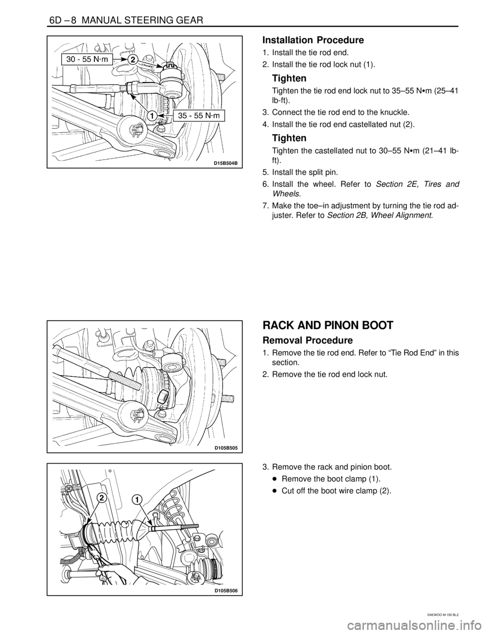
D15B504B
Installation Procedure
1. Install the tie rod end.
2. Install the tie rod lock nut (1).
Tighten
Tighten the tie rod end lock nut to 35–55 N�m (25–41
lb-ft).
3. Connect the tie rod end to the knuckle.
4. Install the tie rod end castellated nut (2).
Tighten
Tighten the castellated nut to 30–55 N�m (21–41 lb-
ft).
5. Install the split pin.
6. Install the wheel. Refer to Section 2E, Tires and
Wheels.
7. Make the toe–in adjustment by turning the tie rod ad-
juster. Refer to Section 2B, Wheel Alignment.
D105B505
RACK AND PINON BOOT
Removal Procedure
1. Remove the tie rod end. Refer to “Tie Rod End” in this
section.
2. Remove the tie rod end lock nut.
D105B506
3. Remove the rack and pinion boot.
�Remove the boot clamp (1).
�Cut off the boot wire clamp (2).


D105B401
1. Manual Steering Gear
2. Steering")