Page 423 of 1184

DAEWOO M-150 BL2
SECTION 1G
ENGINE EXHAUST
TABLE OF CONTENTS
Description and Operation 1G-2. . . . . . . . . . . . . . . . . .
Exhaust System 1G-2. . . . . . . . . . . . . . . . . . . . . . . . . . .
Muffler 1G-2. . . . . . . . . . . . . . . . . . . . . . . . . . . . . . . . . . .
Catalytic Converter 1G-2. . . . . . . . . . . . . . . . . . . . . . . .
Component Locator 1G-3. . . . . . . . . . . . . . . . . . . . . . . .
Exhaust System 1G-3. . . . . . . . . . . . . . . . . . . . . . . . . . . Repair Instruction 1G-4. . . . . . . . . . . . . . . . . . . . . . . . . .
On-Vehicle Service 1G-4. . . . . . . . . . . . . . . . . . . . . . . . . .
Exhaust Pipe/Catalytic Converter 1G-4. . . . . . . . . . . .
Pup-up Catalitic Converter 1G-5. . . . . . . . . . . . . . . . . .
Front Muffler 1G-7. . . . . . . . . . . . . . . . . . . . . . . . . . . . . .
Rear Muffler 1G-8. . . . . . . . . . . . . . . . . . . . . . . . . . . . . .
Specifications 1G-9. . . . . . . . . . . . . . . . . . . . . . . . . . . . .
Fastener Tightening Specifications 1G-9. . . . . . . . . . .
Page 424 of 1184

1G – 2 ENGINE EXHAUST
DAEWOO M-150 BL2
DESCRIPTION AND OPERATION
EXHAUST SYSTEM
Notice: When you are inspecting or replacing exhaust
system components, make sure there is adequate clear-
ance from all points on the underbody to avoid possible
overheating of the floor pan and possible damage to the
passenger compartment insulation and trim materials.
Check the complete exhaust system and the nearby
body areas and tailgate for broken, damaged, missing or
mispositioned parts, open seams, holes, loose connec-
tions or other deterioration which could permit exhaust
fumes to seep into the luggage or passenger compart-
ment. Dust or water in the luggage may be an indication
of a problem in one of these areas. Any defects should
be corrected immediately.
MUFFLER
The muffler reduces the temperature, pressure, and
noise of the exhaust gas.
Aside from the exhaust manifold connection, the ex-
haust system uses a flange and seal joint design op-
posed to a slip joint coupling design with clamp. If holes,
open seams or any deterioration is discovered upon in-
spection of the front muffler and pipe assembly, thecomplete assembly should be replaced. The same pro-
cedure is applicable to the rear muffler assembly.
Heat shields in the front and rear muffler assembly posi-
tions, as well as for the catalytic converter and front ex-
haust pipe, protect the vehicle and the environment from
high temperatures the exhaust system develops.
CATALYTIC CONVERTER
Notice: When jacking or lifting the vehicle from the body
side rails, be certain that the lift pads do not contact the
catalytic converter as this could damage the catalytic
converter.
Notice: The catalytic converter requires the use of un-
leaded fuel only, or damage to the catalyst will result.
The catalytic converter is an emission control device
added to the exhaust system to reduce pollutants from
the exhaust pipes.
The oxidation catalyst is coated with a catalytic material
containing platinum and palladium, which reduces levels
of hydrocarbon (HC) and carbon monoxide (CO) from
the exhaust gas. The three-way catalyst has coatings
which contain platinum and rhodium, which additionally
lower the levels of oxides of nitrogen (NOx).
Page 425 of 1184
ENGINE EXHAUST 1G–3
DAEWOO M-150 BL2
COMPONENT LOCATOR
EXHAUST SYSTEM
D12G4011
1 Pup-up Catalytic Converter
2 Front Exhaust Pipe/Catalytic Converter
Assembly3 Front Muffler Pipe
4 Rear Muffler Pipe
Page 426 of 1184
1G–4 ENGINE EXHAUST
DAEWOO M-150 BL2
REPAIR INSTRUCTIONS
ON–VEHICLE SERVICE
MAA1G010
EXHAUST PIPE/CATALYTIC
CONVERTER
Caution : Make sure to confirm that the components
is cool. And do work.
Removal Procedure
1. Remove the floor console. Refer to Section 9G, Inte-
rior Trim, if equipped Heated Oxygen Sensor (HO2S).
2. Disconnect HO2S connector.
D102G501
3. Remove the front exhaust pipe from the exhaust
manifold or pup-up catalytic converter.
�Remove the nuts (1).
�Remove the gasket (2).
4. Check the gasket for damage or crack.
D102G502
5. Remove the front exhaust pipe from the front muffler
pipe.
�Remove the nuts (1).
Page 427 of 1184

ENGINE EXHAUST 1G–5
DAEWOO M-150 BL2
D102G503
6. Remove the front exhaust pipe and the catalytic con-
verter assembly.
a. Front exhaust pipe.
b. Catalytic converter.
7. Clean the sealing surfaces on the front exhaust pipe
flange and the exhaust manifold.
8. Check the exhaust pipe and the catalytic coverter for
holes, damage, open seams, or other deterioration
which could permit exhaust fumes to seep into the
passenger compartment.
D12G504A
25–35 N�m
25–35 N�m
Installation Procedure
1. Using the nuts and the gasket, secure the front ex-
haust pipe and the catalytic converter assembly to
the exhaust manifold.
Tighten
Tighten the nuts to 25–35 N�m (18–25 lb-ft).
a. Front exhaust pipe nut.
2. Install the front exhaust pipe and the catalytic con-
verter assembly to the front muffler pipe flange. Use
the nuts to secure the front exhaust pipe and the cat-
alytic converter assembly.
Tighten
Tighten the nuts to 25–35 N�m (18–25 lb-ft).
b. Front muffler pipe nut.
Notice : Make sure not to contact the components with
the underbody.
3. Connect the Heated Oxygen Sensor (HO2S) connec-
tor.
4. Install the floor console. Refer to Section 9G, Interior
Trim.
D102G501
PUP-UP CATALITIC CONVERTER
Removal Procedure
1. Remove the front exhaust pipe from the pup-up cata-
litic converter.
�Remove the nuts (1).
�Remove the gasket (2).
2. Check the gasket for damage or leak.
Page 431 of 1184
ENGINE EXHAUST 1G–9
DAEWOO M-150 BL2
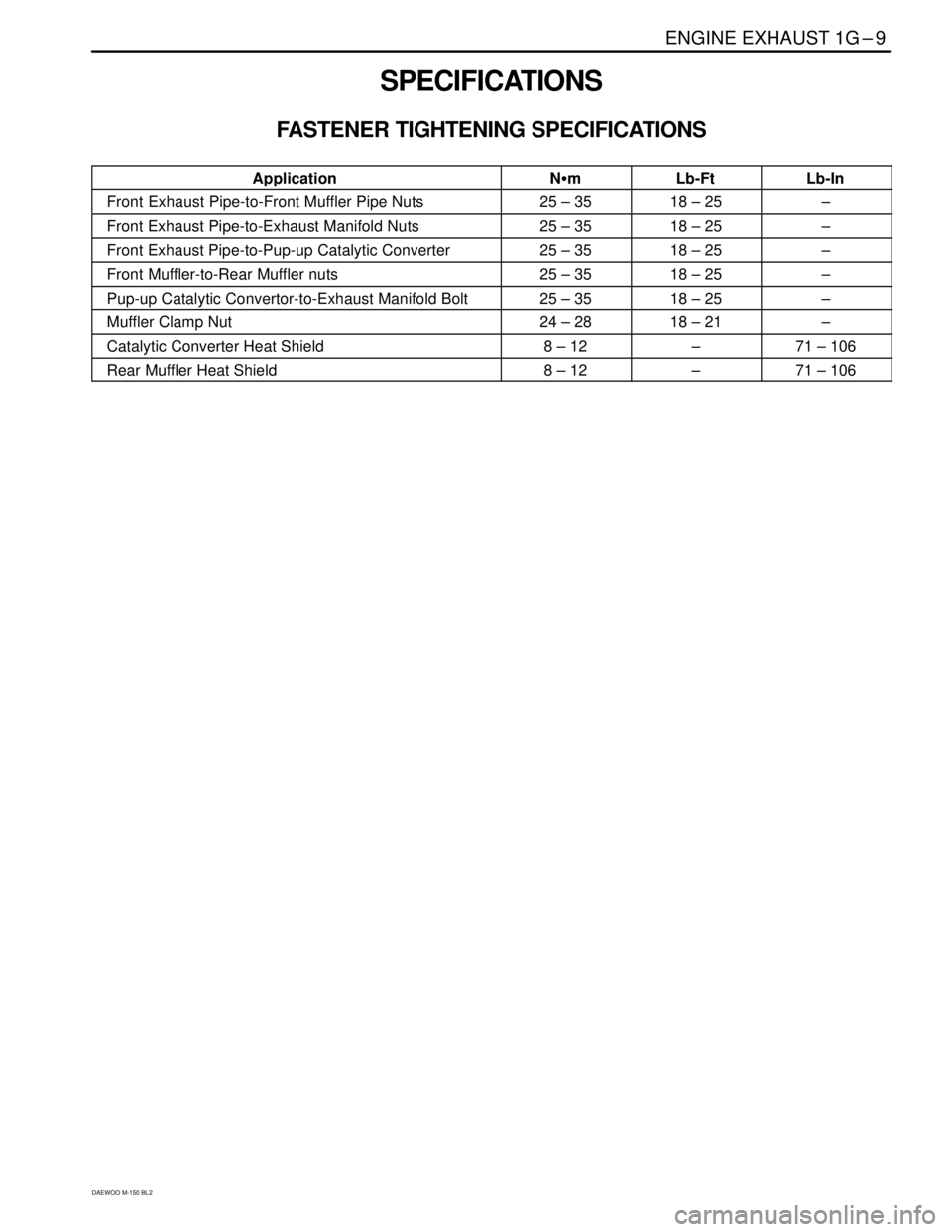
SPECIFICATIONS
FASTENER TIGHTENING SPECIFICATIONS
ApplicationN�mLb-FtLb-In
Front Exhaust Pipe-to-Front Muffler Pipe Nuts25 – 3518 – 25–
Front Exhaust Pipe-to-Exhaust Manifold Nuts25 – 3518 – 25–
Front Exhaust Pipe-to-Pup-up Catalytic Converter25 – 3518 – 25–
Front Muffler-to-Rear Muffler nuts25 – 3518 – 25–
Pup-up Catalytic Convertor-to-Exhaust Manifold Bolt25 – 3518 – 25–
Muffler Clamp Nut24 – 2818 – 21–
Catalytic Converter Heat Shield8 – 12–71 – 106
Rear Muffler Heat Shield8 – 12–71 – 106
Page 1081 of 1184

FRAME AND UNDERBODY 9N–3
DAEWOO M-150 BL2
REPAIR INSTRUCTIONS
ON–VEHICLE SERVICE
ALIGNMENT CHECKING
An accurate method of determining the alignment of the
underbody uses a measuring tram gauge. The tram
gauge set used to perform the recommended measuring
checks must include a vertical pointer able to reach
457 mm (18 inches).
Two types of measurements can be made with a tram
gauge: direct point-to-point measurements and mea-
surements calculated on a horizontal plane (datum line)
parallel to the underbody. Point-to-point measurements
are generally taken on steering and suspension engine
compartment parts and simply require the vertical point-
ers to be set equally.
For horizontal plane measurements, the vertical pointers
must be set as specified for each point to be measured.
Dimensions-to-gauge holes are measured to the center
of the holes and flush to the adjacent surface metal un-
less otherwise specified. It is recommended that the di-
agonal dimensions to the cross-body be checked on
both sides in order to verify the dimensional accuracy of
the vehicle underbody.
FLOOR PAN INSULATORS
The floor pan insulators have been designed for the
higher floor pan temperatures that result from the use
of the catalytic converter in the exhaust system. There-
fore, when servicing a vehicle, it is essential that any in-sulators that may have been disturbed or removed be
reinstalled in the original sequence and location. Also, if
an insulator needs to be replaced, use only the insula-
tion specified for that location on the floor pan.
When servicing or replacing interior insulators, observe
the following instructions.
�Install the insulators in the original position and se-
quence. Butt the pieces together in order to avoid
gapping or overlapping.
�If it is necessary to replace an insulator, use only the
specified insulation.
�Use the original part to determine the amount of re-
placement material required and as a template for
cutting and fitting the new piece to the floor pan.
�When installing the insulator, do not enlarge any cut-
outs or holes that are used for the attachment of interi-
or parts such as the instrument panel or the floor
console.
�Route the cross-body harness for interior parts over
the floor pan insulators. Clip it in the original location.
�Do not apply spray-on deadeners or trim adhesives to
the top of the floor pan at the area directly over the
catalytic converter or the muffler.
Any insulator service repair or replacement should be
the same thickness, size, and location as the original
installation in the vehicle.