2003 CHRYSLER CARAVAN differential
[x] Cancel search: differentialPage 1516 of 2177
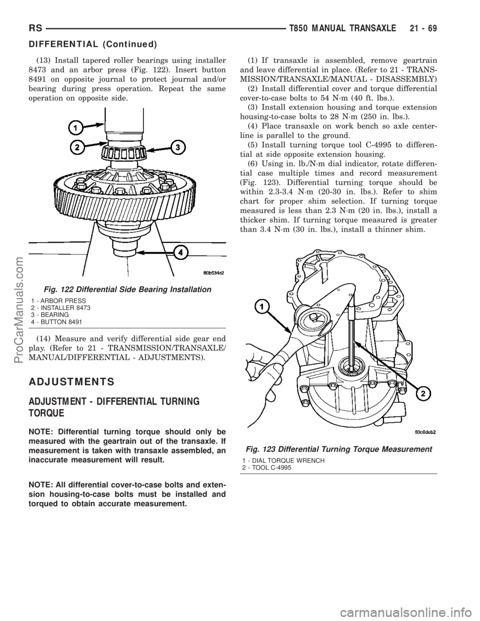
(13) Install tapered roller bearings using installer
8473 and an arbor press (Fig. 122). Insert button
8491 on opposite journal to protect journal and/or
bearing during press operation. Repeat the same
operation on opposite side.
(14) Measure and verify differential side gear end
play. (Refer to 21 - TRANSMISSION/TRANSAXLE/
MANUAL/DIFFERENTIAL - ADJUSTMENTS).
ADJUSTMENTS
ADJUSTMENT - DIFFERENTIAL TURNING
TORQUE
NOTE: Differential turning torque should only be
measured with the geartrain out of the transaxle. If
measurement is taken with transaxle assembled, an
inaccurate measurement will result.
NOTE: All differential cover-to-case bolts and exten-
sion housing-to-case bolts must be installed and
torqued to obtain accurate measurement.(1) If transaxle is assembled, remove geartrain
and leave differential in place. (Refer to 21 - TRANS-
MISSION/TRANSAXLE/MANUAL - DISASSEMBLY)
(2) Install differential cover and torque differential
cover-to-case bolts to 54 N´m (40 ft. lbs.).
(3) Install extension housing and torque extension
housing-to-case bolts to 28 N´m (250 in. lbs.).
(4) Place transaxle on work bench so axle center-
line is parallel to the ground.
(5) Install turning torque tool C-4995 to differen-
tial at side opposite extension housing.
(6) Using in. lb./N´m dial indicator, rotate differen-
tial case multiple times and record measurement
(Fig. 123). Differential turning torque should be
within 2.3-3.4 N´m (20-30 in. lbs.). Refer to shim
chart for proper shim selection. If turning torque
measured is less than 2.3 N´m (20 in. lbs.), install a
thicker shim. If turning torque measured is greater
than 3.4 N´m (30 in. lbs.), install a thinner shim.
Fig. 122 Differential Side Bearing Installation
1 - ARBOR PRESS
2 - INSTALLER 8473
3 - BEARING
4 - BUTTON 8491
Fig. 123 Differential Turning Torque Measurement
1 - DIAL TORQUE WRENCH
2 - TOOL C-4995
RST850 MANUAL TRANSAXLE21-69
DIFFERENTIAL (Continued)
ProCarManuals.com
Page 1517 of 2177
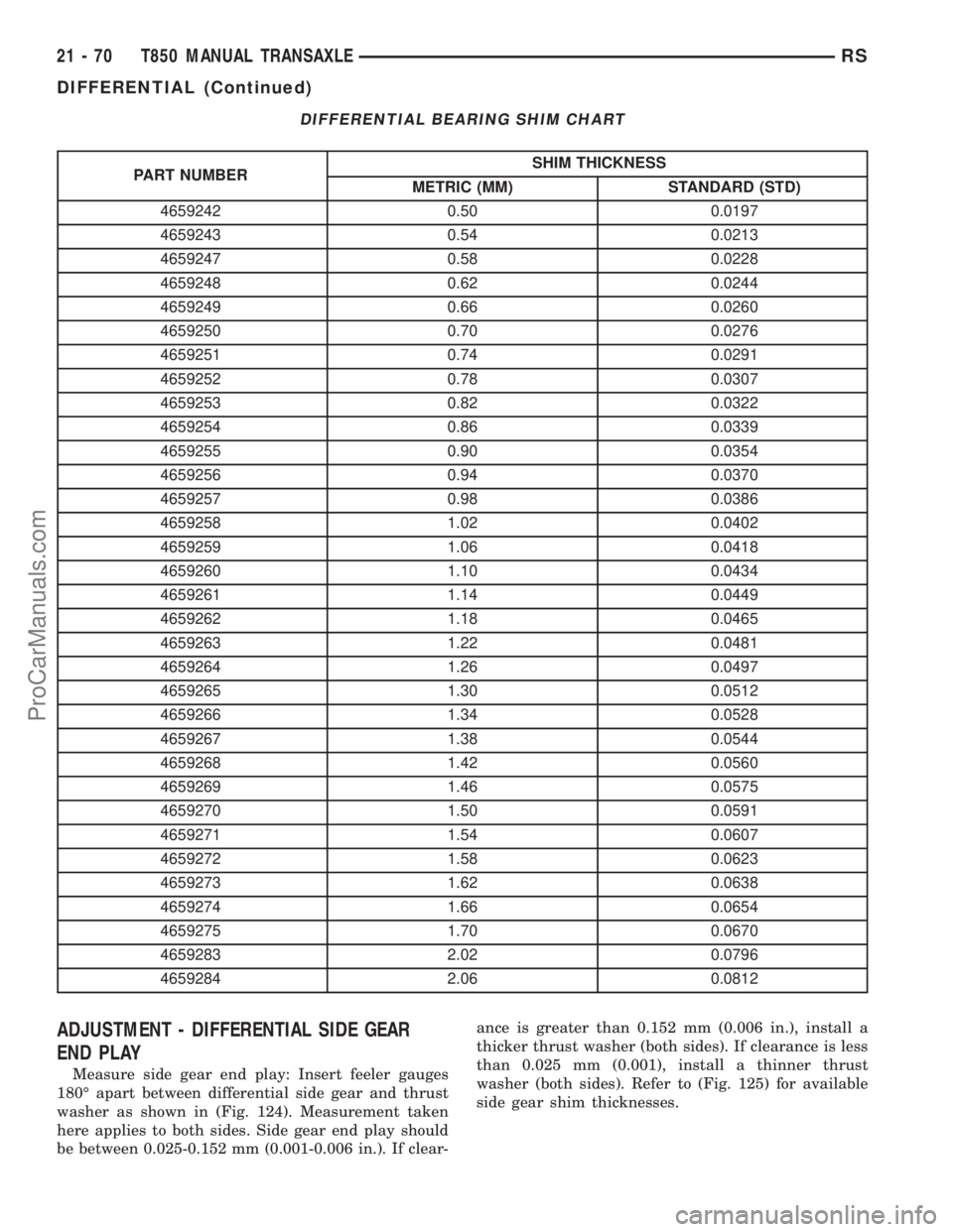
DIFFERENTIAL BEARING SHIM CHART
PART NUMBERSHIM THICKNESS
METRIC (MM) STANDARD (STD)
4659242 0.50 0.0197
4659243 0.54 0.0213
4659247 0.58 0.0228
4659248 0.62 0.0244
4659249 0.66 0.0260
4659250 0.70 0.0276
4659251 0.74 0.0291
4659252 0.78 0.0307
4659253 0.82 0.0322
4659254 0.86 0.0339
4659255 0.90 0.0354
4659256 0.94 0.0370
4659257 0.98 0.0386
4659258 1.02 0.0402
4659259 1.06 0.0418
4659260 1.10 0.0434
4659261 1.14 0.0449
4659262 1.18 0.0465
4659263 1.22 0.0481
4659264 1.26 0.0497
4659265 1.30 0.0512
4659266 1.34 0.0528
4659267 1.38 0.0544
4659268 1.42 0.0560
4659269 1.46 0.0575
4659270 1.50 0.0591
4659271 1.54 0.0607
4659272 1.58 0.0623
4659273 1.62 0.0638
4659274 1.66 0.0654
4659275 1.70 0.0670
4659283 2.02 0.0796
4659284 2.06 0.0812
ADJUSTMENT - DIFFERENTIAL SIDE GEAR
END PLAY
Measure side gear end play: Insert feeler gauges
180É apart between differential side gear and thrust
washer as shown in (Fig. 124). Measurement taken
here applies to both sides. Side gear end play should
be between 0.025-0.152 mm (0.001-0.006 in.). If clear-ance is greater than 0.152 mm (0.006 in.), install a
thicker thrust washer (both sides). If clearance is less
than 0.025 mm (0.001), install a thinner thrust
washer (both sides). Refer to (Fig. 125) for available
side gear shim thicknesses.
21 - 70 T850 MANUAL TRANSAXLERS
DIFFERENTIAL (Continued)
ProCarManuals.com
Page 1518 of 2177
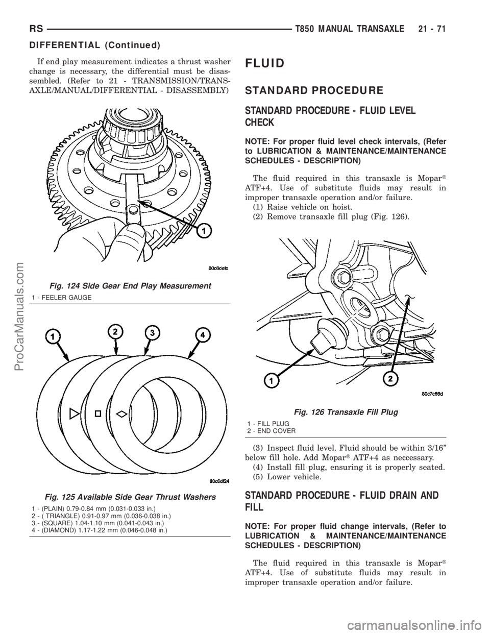
If end play measurement indicates a thrust washer
change is necessary, the differential must be disas-
sembled. (Refer to 21 - TRANSMISSION/TRANS-
AXLE/MANUAL/DIFFERENTIAL - DISASSEMBLY)FLUID
STANDARD PROCEDURE
STANDARD PROCEDURE - FLUID LEVEL
CHECK
NOTE: For proper fluid level check intervals, (Refer
to LUBRICATION & MAINTENANCE/MAINTENANCE
SCHEDULES - DESCRIPTION)
The fluid required in this transaxle is Mopart
ATF+4. Use of substitute fluids may result in
improper transaxle operation and/or failure.
(1) Raise vehicle on hoist.
(2) Remove transaxle fill plug (Fig. 126).
(3) Inspect fluid level. Fluid should be within 3/16º
below fill hole. Add MopartATF+4 as neccessary.
(4) Install fill plug, ensuring it is properly seated.
(5) Lower vehicle.
STANDARD PROCEDURE - FLUID DRAIN AND
FILL
NOTE: For proper fluid change intervals, (Refer to
LUBRICATION & MAINTENANCE/MAINTENANCE
SCHEDULES - DESCRIPTION)
The fluid required in this transaxle is Mopart
ATF+4. Use of substitute fluids may result in
improper transaxle operation and/or failure.
Fig. 124 Side Gear End Play Measurement
1 - FEELER GAUGE
Fig. 125 Available Side Gear Thrust Washers
1 - (PLAIN) 0.79-0.84 mm (0.031-0.033 in.)
2 - ( TRIANGLE) 0.91-0.97 mm (0.036-0.038 in.)
3 - (SQUARE) 1.04-1.10 mm (0.041-0.043 in.)
4 - (DIAMOND) 1.17-1.22 mm (0.046-0.048 in.)
Fig. 126 Transaxle Fill Plug
1 - FILL PLUG
2 - END COVER
RST850 MANUAL TRANSAXLE21-71
DIFFERENTIAL (Continued)
ProCarManuals.com
Page 1519 of 2177
FLUID DRAIN
(1) Raise vehicle on hoist.
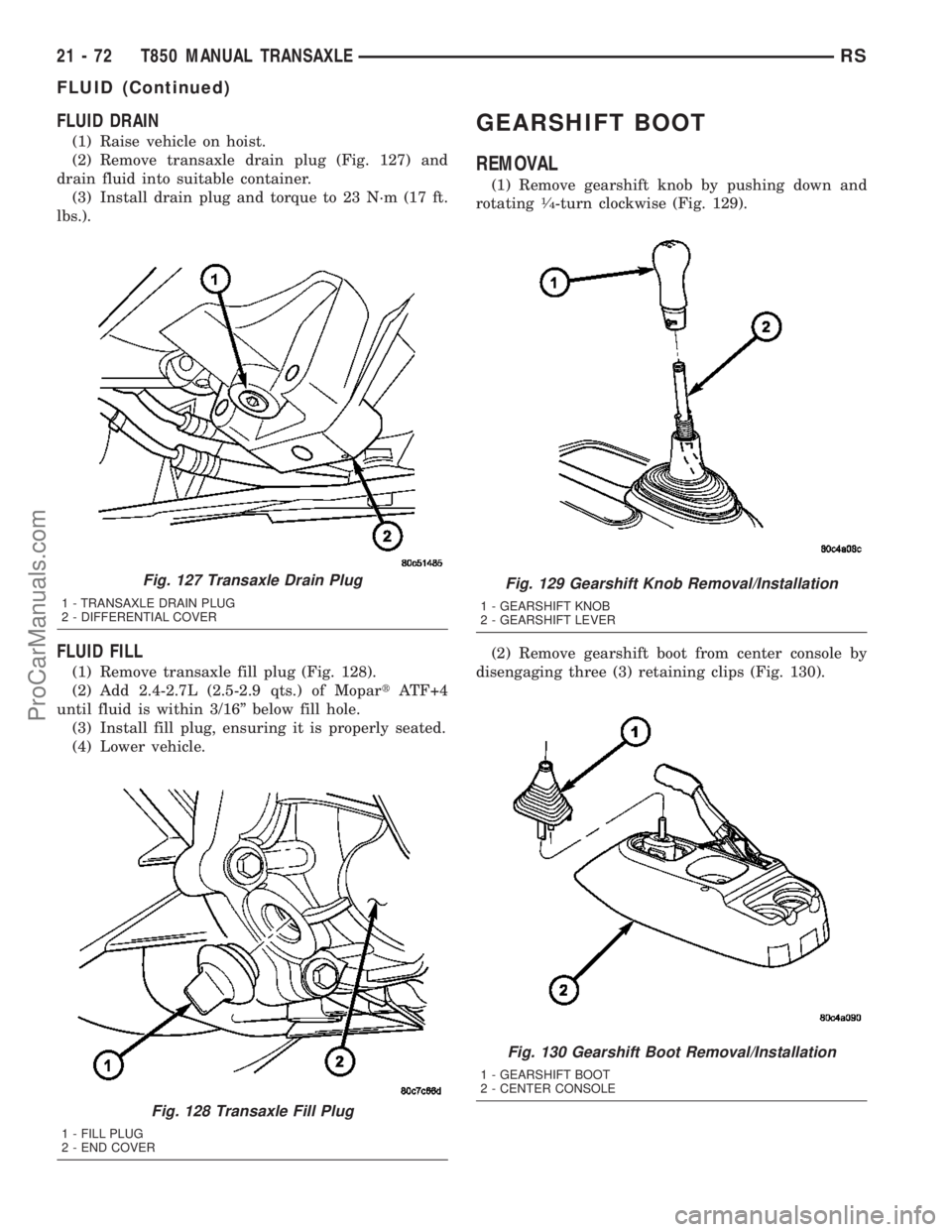
(2) Remove transaxle drain plug (Fig. 127) and
drain fluid into suitable container.
(3) Install drain plug and torque to 23 N´m (17 ft.
lbs.).
FLUID FILL
(1) Remove transaxle fill plug (Fig. 128).
(2) Add 2.4-2.7L (2.5-2.9 qts.) of MopartATF+4
until fluid is within 3/16º below fill hole.
(3) Install fill plug, ensuring it is properly seated.
(4) Lower vehicle.
GEARSHIFT BOOT
REMOVAL
(1) Remove gearshift knob by pushing down and
rotating1¤4-turn clockwise (Fig. 129).
(2) Remove gearshift boot from center console by
disengaging three (3) retaining clips (Fig. 130).
Fig. 127 Transaxle Drain Plug
1 - TRANSAXLE DRAIN PLUG
2 - DIFFERENTIAL COVER
Fig. 128 Transaxle Fill Plug
1 - FILL PLUG
2 - END COVER
Fig. 129 Gearshift Knob Removal/Installation
1 - GEARSHIFT KNOB
2 - GEARSHIFT LEVER
Fig. 130 Gearshift Boot Removal/Installation
1 - GEARSHIFT BOOT
2 - CENTER CONSOLE
21 - 72 T850 MANUAL TRANSAXLERS
FLUID (Continued)
ProCarManuals.com
Page 1547 of 2177
INTERMEDIATE SHAFT
DESCRIPTION
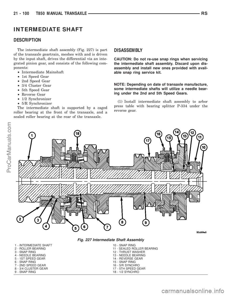
The intermediate shaft assembly (Fig. 227) is part
of the transaxle geartrain, meshes with and is driven
by the input shaft, drives the differential via an inte-
grated pinion gear, and consists of the following com-
ponents:
²Intermediate Mainshaft
²1st Speed Gear
²2nd Speed Gear
²3/4 Cluster Gear
²5th Speed Gear
²Reverse Gear
²1/2 Synchronizer
²5/R Synchronizer
The intermediate shaft is supported by a caged
roller bearing at the front of the transaxle, and a
sealed roller bearing at the rear of the transaxle.DISASSEMBLY
CAUTION: Do not re-use snap rings when servicing
the intermediate shaft assembly. Discard upon dis-
assembly and install new ones provided with avail-
able snap ring service kit.
NOTE: Depending on date of transaxle manufacture,
some intermediate shafts will utilize a needle bear-
ing under the 2nd and 5th Speed Gears.
(1) Install intermediate shaft assembly to arbor
press table with bearing splitter P-334 under the
reverse gear.
Fig. 227 Intermediate Shaft Assembly
1 - INTERMEDIATE SHAFT 10 - SNAP RING
2 - ROLLER BEARING 11 - SEALED ROLLER BEARING
3 - SNAP RING 12 - THRUST WASHER
4 - NEEDLE BEARING 13 - NEEDLE BEARING
5 - 1ST SPEED GEAR 14 - REVERSE GEAR
6 - SNAP RING 15 - SNAP RING
7 - 2ND SPEED GEAR 16 - 5/R SYNCHRO
8 - 3/4 CLUSTER GEAR 17 - 5TH SPEED GEAR
9 - SNAP RING 18 - 1/2 SYNCHRO
21 - 100 T850 MANUAL TRANSAXLERS
ProCarManuals.com
Page 1563 of 2177
41TE AUTOMATIC TRANSAXLE
TABLE OF CONTENTS
page page
41TE AUTOMATIC TRANSAXLE
DESCRIPTION........................117
OPERATION..........................119
DIAGNOSIS AND TESTING
DIAGNOSIS AND TESTING - 41TE
TRANSAXLE GENERAL DIAGNOSIS......119
DIAGNOSIS AND TESTING - ROAD TEST . . 119
DIAGNOSIS AND TESTING - HYDRAULIC
PRESSURE TESTS...................120
DIAGNOSIS AND TESTING - CLUTCH AIR
PRESSURE TESTS...................122
DIAGNOSIS AND TESTING - TORQUE
CONVERTER HOUSING FLUID LEAKAGE . . 123
REMOVAL............................124
DISASSEMBLY........................125
ASSEMBLY...........................144
INSTALLATION........................166
SCHEMATICS AND DIAGRAMS
41TE TRANSAXLE HYDRAULIC
SCHEMATICS.......................169
SPECIFICATIONS - 41TE TRANSAXLE......181
SPECIAL TOOLS
41TE AUTOMATIC TRANSAXLE.........183
ACCUMULATOR
DESCRIPTION........................188
OPERATION..........................189
AUTOSTICK SWITCH
DESCRIPTION........................189
OPERATION..........................189
DRIVING CLUTCHES
DESCRIPTION........................190
OPERATION..........................190
FINAL DRIVE
DISASSEMBLY........................190
ASSEMBLY...........................195
ADJUSTMENTS
ADJUSTMENT - DIFFERENTIAL BEARING
PRELOAD..........................199
FLUID
STANDARD PROCEDURE
FLUID LEVEL AND CONDITION CHECK . . . 201
STANDARD PROCEDURE - FLUID AND
FILTER SERVICE.....................203
GEAR SHIFT CABLE
REMOVAL............................204
INSTALLATION........................205
ADJUSTMENTS
GEARSHIFT CABLE ADJUSTMENT.......206HOLDING CLUTCHES
DESCRIPTION........................207
OPERATION..........................207
INPUT CLUTCH ASSEMBLY
DISASSEMBLY........................208
ASSEMBLY...........................216
OIL PUMP
DESCRIPTION........................230
OPERATION..........................230
DISASSEMBLY........................230
ASSEMBLY...........................232
PLANETARY GEARTRAIN
DESCRIPTION........................232
OPERATION..........................232
SEAL - OIL PUMP
REMOVAL............................232
INSTALLATION........................233
SHIFT INTERLOCK SOLENOID
DESCRIPTION........................233
OPERATION..........................233
DIAGNOSIS AND TESTING - BRAKE/
TRANSMISSION SHIFT INTERLOCK
SOLENOID..........................235
REMOVAL............................235
INSTALLATION........................236
SOLENOID/PRESSURE SWITCH ASSY
DESCRIPTION........................237
OPERATION..........................237
REMOVAL............................238
INSTALLATION........................239
SPEED SENSOR - INPUT
DESCRIPTION........................239
OPERATION..........................240
REMOVAL............................240
INSTALLATION........................240
SPEED SENSOR - OUTPUT
DESCRIPTION........................241
OPERATION..........................241
REMOVAL............................241
INSTALLATION........................242
TORQUE CONVERTER
DESCRIPTION........................242
OPERATION..........................245
REMOVAL............................247
INSTALLATION........................247
TRANSMISSION CONTROL RELAY
DESCRIPTION........................247
OPERATION..........................248
21 - 116 41TE AUTOMATIC TRANSAXLERS
ProCarManuals.com
Page 1564 of 2177
TRANSMISSION RANGE SENSOR
DESCRIPTION........................248
OPERATION..........................248
REMOVAL............................249
INSTALLATION........................249
TRD LINK
DESCRIPTION........................249
OPERATION..........................249VALVE BODY
DESCRIPTION........................250
OPERATION..........................250
REMOVAL............................251
DISASSEMBLY........................252
ASSEMBLY...........................257
INSTALLATION........................262
41TE AUTOMATIC
TRANSAXLE
DESCRIPTION
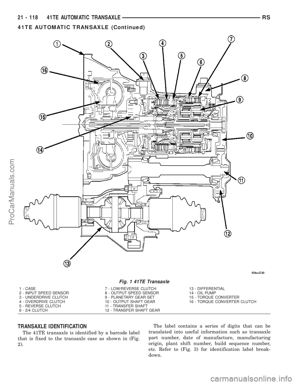
The 41TE (Fig. 1) is a four-speed transaxle that is
a conventional hydraulic/mechanical assembly with
an integral differential, and is controlled with adap-
tive electronic controls and monitors. The hydraulic
system of the transaxle consists of the transaxle
fluid, fluid passages, hydraulic valves, and various
line pressure control components. An input clutch
assembly which houses the underdrive, overdrive,
and reverse clutches is used. It also utilizes separate
holding clutches: 2nd/4th gear and Low/Reverse. The
primary mechanical components of the transaxle con-
sist of the following:
²Three multiple disc input clutches
²Two multiple disc holding clutches
²Four hydraulic accumulators
²Two planetary gear sets
²Hydraulic oil pump
²Valve body
²Solenoid/Pressure switch assembly
²Integral differential assemblyControl of the transaxle is accomplished by fully
adaptive electronics. Optimum shift scheduling is
accomplished through continuous real-time sensor
feedback information provided to the Powertrain
Control Module (PCM) or Transmission Control Mod-
ule (TCM).
The PCM/TCM is the heart of the electronic control
system and relies on information from various direct
and indirect inputs (sensors, switches, etc.) to deter-
mine driver demand and vehicle operating condi-
tions. With this information, the PCM/TCM can
calculate and perform timely and quality shifts
through various output or control devices (solenoid
pack, transmission control relay, etc.).
The PCM/TCM also performs certain self-diagnos-
tic functions and provides comprehensive information
(sensor data, DTC's, etc.) which is helpful in proper
diagnosis and repair. This information can be viewed
with the DRB scan tool.
RS41TE AUTOMATIC TRANSAXLE21 - 117
ProCarManuals.com
Page 1565 of 2177
TRANSAXLE IDENTIFICATION
The 41TE transaxle is identified by a barcode label
that is fixed to the transaxle case as shown in (Fig.
2).The label contains a series of digits that can be
translated into useful information such as transaxle
part number, date of manufacture, manufacturing
origin, plant shift number, build sequence number,
etc. Refer to (Fig. 3) for identification label break-
down.
Fig. 1 41TE Transaxle
1 - CASE 7 - LOW/REVERSE CLUTCH 13 - DIFFERENTIAL
2 - INPUT SPEED SENSOR 8 - OUTPUT SPEED SENSOR 14 - OIL PUMP
3 - UNDERDRIVE CLUTCH 9 - PLANETARY GEAR SET 15 - TORQUE CONVERTER
4 - OVERDRIVE CLUTCH 10 - OUTPUT SHAFT GEAR 16 - TORQUE CONVERTER CLUTCH
5 - REVERSE CLUTCH 11 - TRANSFER SHAFT
6 - 2/4 CLUTCH 12 - TRANSFER SHAFT GEAR
21 - 118 41TE AUTOMATIC TRANSAXLERS
41TE AUTOMATIC TRANSAXLE (Continued)
ProCarManuals.com