Page 1508 of 2177

AXLE SEALS
REMOVAL
(1) Raise vehicle on hoist.
(2) Remove one or both front halfshaft assemblies.
(Refer to 3 - DIFFERENTIAL & DRIVELINE/HALF
SHAFT - REMOVAL)
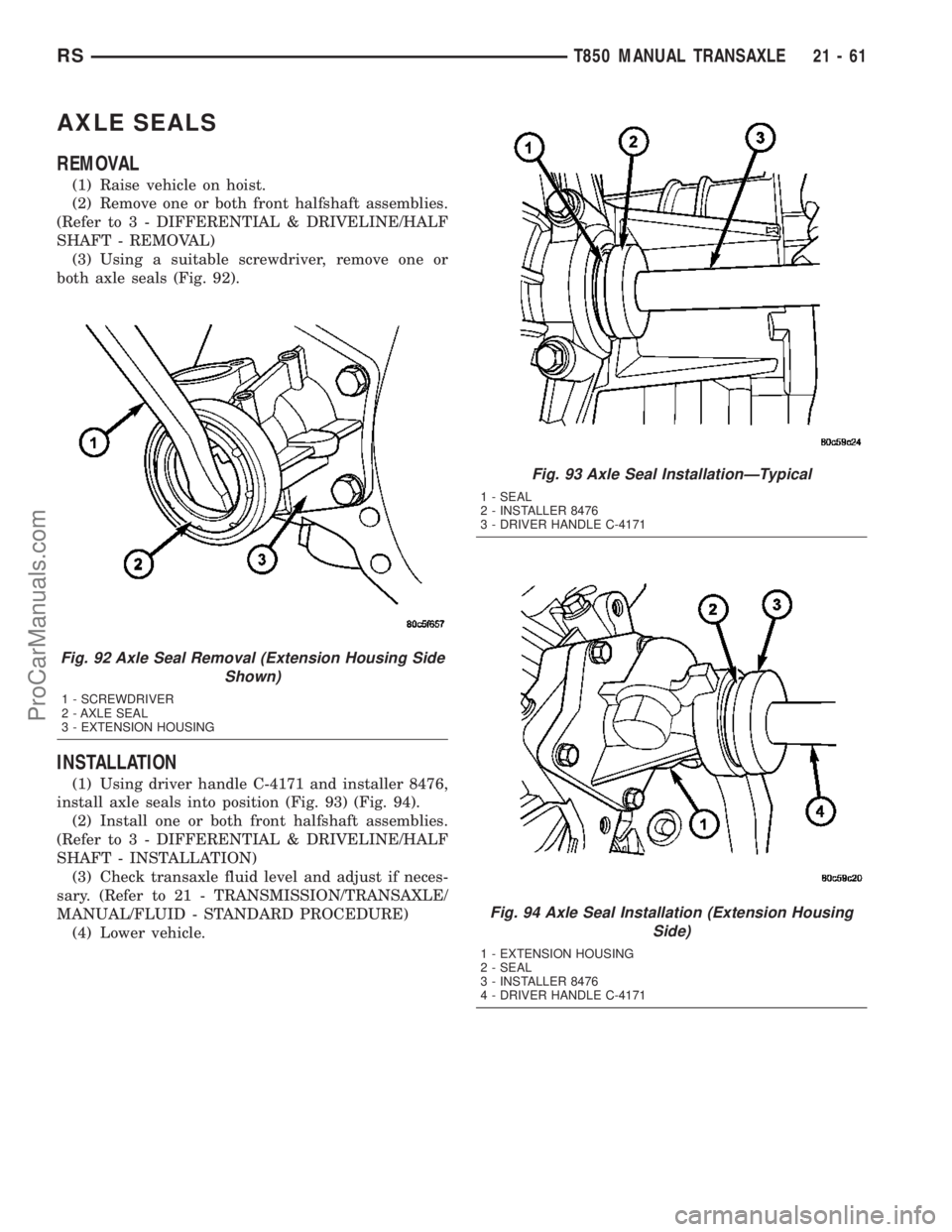
(3) Using a suitable screwdriver, remove one or
both axle seals (Fig. 92).
INSTALLATION
(1) Using driver handle C-4171 and installer 8476,
install axle seals into position (Fig. 93) (Fig. 94).
(2) Install one or both front halfshaft assemblies.
(Refer to 3 - DIFFERENTIAL & DRIVELINE/HALF
SHAFT - INSTALLATION)
(3) Check transaxle fluid level and adjust if neces-
sary. (Refer to 21 - TRANSMISSION/TRANSAXLE/
MANUAL/FLUID - STANDARD PROCEDURE)
(4) Lower vehicle.
Fig. 92 Axle Seal Removal (Extension Housing Side
Shown)
1 - SCREWDRIVER
2 - AXLE SEAL
3 - EXTENSION HOUSING
Fig. 93 Axle Seal InstallationÐTypical
1 - SEAL
2 - INSTALLER 8476
3 - DRIVER HANDLE C-4171
Fig. 94 Axle Seal Installation (Extension Housing
Side)
1 - EXTENSION HOUSING
2 - SEAL
3 - INSTALLER 8476
4 - DRIVER HANDLE C-4171
RST850 MANUAL TRANSAXLE21-61
ProCarManuals.com
Page 1509 of 2177

BACK-UP LAMP SWITCH
REMOVAL
(1) Raise vehicle on hoist.
(2) Disconnect back-up lamp switch connector.
(3) Remove back-up lamp switch (Fig. 95).
INSTALLATION
(1) Install back-up lamp switch (Fig. 95) and
torque to 23 N´m (17 ft. lbs.) using Tool 8827.
(2) Connect back-up lamp switch connector.
(3) Lower vehicle.
DIFFERENTIAL
DESCRIPTION
The T850 differential is a conventional open design.
It consists of a ring gear and a two-piece differential
case. The differential case contains the pinion and side
gears, three floating pinion shafts, and a pinion shaft
retaining ring (Fig. 96). The differential case is sup-
ported in the transaxle by tapered roller bearings.
OPERATION
The differential assembly is driven by the interme-
diate shaft via the ring gear. The ring gear drives the
differential case, and the case drives the halfshafts
through the differential gears. The differential pinion
and side gears are supported in the case by pinion
shafts and thrust washers. Differential pinion and
side gears make it possible for front wheels to rotate
at different speeds while cornering.
DISASSEMBLY
(1) Remove differential side bearings:
(a) Install button 8491-1 to differential case (Fig.
97).(b) Set up Tool 5048 (5048-1, -4, -6) as shown in
(Fig. 98).
(c) Remove differential side bearing (Fig. 99).
Same procedure/tools work for both sides.
Fig. 95 Back-Up Lamp Switch
1 - BACK-UP LAMP SWITCH
Fig. 96 Differential Assembly
1 - RING GEAR
2 - SUPPORT PLATE
3 - SIDE GEAR (2)
4 - PINION GEAR (4)
5 - BOLT (12)
6 - PINION SHAFT (2-SHORT)
7 - PINION SHAFT (1-LONG)
8 - THRUST WASHER (2)
9 - RETAINING RING
10 - DIFFERENTIAL CASE
Fig. 97 Tool 8491
1 - TOOL 8491
21 - 62 T850 MANUAL TRANSAXLERS
ProCarManuals.com
Page 1510 of 2177
(2) Remove ring gear-to-case bolts (Fig. 100) and
remove ring gear.
(3) Using three ring gear bolts as forcing screws
(Fig. 101), separate differential support from case
(Fig. 102).
Fig. 98 Puller 5048
1 - 5048-1 FORCING SCREW
2 - 5048-4 COLLETS
3 - 5048-6 SLEEVE
Fig. 99 Differential Side Bearing Removal
1 - TOOL 5048
Fig. 100 Ring Gear-to-Differential Case Bolts
1 - BOLT (12)
2 - DIFFERENTIAL SUPPORT
3 - RING GEAR
Fig. 101 Separate Differential Case Halves
1 - BOLT (3)
2 - DIFFERENTIAL CASE
3 - DIFFERENTIAL SUPPORT
RST850 MANUAL TRANSAXLE21-63
DIFFERENTIAL (Continued)
ProCarManuals.com
Page 1511 of 2177
(4) Remove side gear thrust washer (Fig. 103).(5) Remove side gear (Fig. 104).
(6) Remove long pinion shaft (Fig. 105).
Fig. 102 Differential Support Plate
1 - DIFFERENTIAL SUPPORT PLATE
2 - DIFFERENTIAL CASE
Fig. 103 Side Gear Thrust Washer
1 - SIDE GEAR THRUST WASHER
2 - DIFFERENTIAL SIDE GEAR
Fig. 104 Differential Side Gear
1 - DIFFERENTIAL SIDE GEAR
Fig. 105 Long Pinion Shaft
1 - PINION SHAFT (LONG)
21 - 64 T850 MANUAL TRANSAXLERS
DIFFERENTIAL (Continued)
ProCarManuals.com
Page 1512 of 2177
(7) Remove both short pinion shafts (Fig. 106).
(8) Remove pinion shaft retainer (Fig. 107).(9) Remove four pinion gears and thrust washers
(Fig. 108).
(10) Remove side gear (Fig. 109).
Fig. 106 Short Pinion Shaft (2)
1 - PINION SHAFT (SHORT (2))
Fig. 107 Pinion Shaft Retaining Ring
1 - RETAINING RING
Fig. 108 Pinion Gear and Thrust Washer
1 - THRUST WASHER (4)
2 - PINION GEAR (4)
Fig. 109 Differential Side Gear
1 - DIFFERENTIAL SIDE GEAR
RST850 MANUAL TRANSAXLE21-65
DIFFERENTIAL (Continued)
ProCarManuals.com
Page 1513 of 2177
(11) Remove side gear thrust washer (Fig. 110).
ASSEMBLY
(1) Install side gear thrust washer (Fig. 111).(2) Install differential side gear (Fig. 112).
(3) Install four (4) pinion gears and thrust washers
(Fig. 113).
Fig. 110 Side Gear Thrust Washer
1 - SIDE GEAR THRUST WASHER
Fig. 111 Side Gear Thrust Washer
1 - SIDE GEAR THRUST WASHER
Fig. 112 Differential Side Gear
1 - DIFFERENTIAL SIDE GEAR
Fig. 113 Pinion Gear and Thrust Washer
1 - THRUST WASHER (4)
2 - PINION GEAR (4)
21 - 66 T850 MANUAL TRANSAXLERS
DIFFERENTIAL (Continued)
ProCarManuals.com
Page 1514 of 2177
(4) Install pinion shaft retaining ring (Fig. 114).
(5) Install two (2) short pinion shafts (Fig. 115).(6) Install one (1) long pinion shaft (Fig. 116).
(7) Install differential side gear.
(8) Install side gear thrust washer (Fig. 117).
Fig. 114 Pinion Shaft Retaining Ring
1 - RETAINING RING
Fig. 115 Short Pinion Shaft (2)
1 - PINION SHAFT (SHORT (2))
Fig. 116 Long Pinion Shaft
1 - PINION SHAFT (LONG)
Fig. 117 Side Gear Thrust Washer
1 - SIDE GEAR THRUST WASHER
2 - DIFFERENTIAL SIDE GEAR
RST850 MANUAL TRANSAXLE21-67
DIFFERENTIAL (Continued)
ProCarManuals.com
Page 1515 of 2177

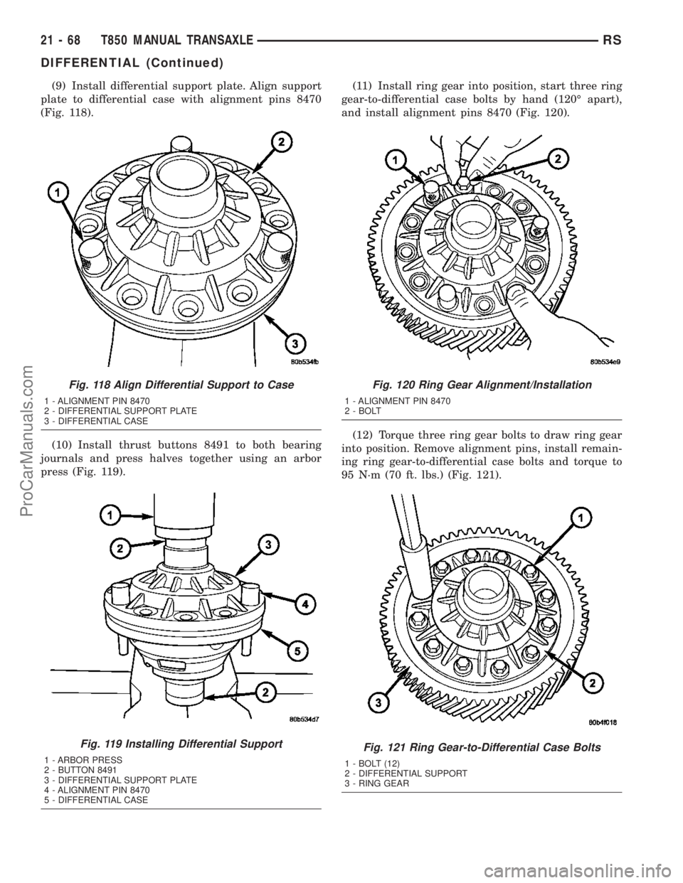
(9) Install differential support plate. Align support
plate to differential case with alignment pins 8470
(Fig. 118).
(10) Install thrust buttons 8491 to both bearing
journals and press halves together using an arbor
press (Fig. 119).(11) Install ring gear into position, start three ring
gear-to-differential case bolts by hand (120É apart),
and install alignment pins 8470 (Fig. 120).
(12) Torque three ring gear bolts to draw ring gear
into position. Remove alignment pins, install remain-
ing ring gear-to-differential case bolts and torque to
95 N´m (70 ft. lbs.) (Fig. 121).
Fig. 118 Align Differential Support to Case
1 - ALIGNMENT PIN 8470
2 - DIFFERENTIAL SUPPORT PLATE
3 - DIFFERENTIAL CASE
Fig. 119 Installing Differential Support
1 - ARBOR PRESS
2 - BUTTON 8491
3 - DIFFERENTIAL SUPPORT PLATE
4 - ALIGNMENT PIN 8470
5 - DIFFERENTIAL CASE
Fig. 120 Ring Gear Alignment/Installation
1 - ALIGNMENT PIN 8470
2 - BOLT
Fig. 121 Ring Gear-to-Differential Case Bolts
1 - BOLT (12)
2 - DIFFERENTIAL SUPPORT
3 - RING GEAR
21 - 68 T850 MANUAL TRANSAXLERS
DIFFERENTIAL (Continued)
ProCarManuals.com