Page 1461 of 2177
INSTALLATION
The power transfer unit input shaft cover seal is
the larger of the two seals located on the inside of
the end cover. The differential bearing cup must be
removed to service this seal.
(1) Clean and inspect seal area.
(2) Use special tool No. MD998803 and install seal
(Fig. 34). When installing seal the spring side of the
seal must face toward the special tool.
Fig. 31 End Cover Removal
1 - END COVER EARS
2 - HAMMER
3 - POWER TRANSFER UNIT
Fig. 32 Bearing Race Removal
1 - END COVER
2 - SPECIAL TOOL
No. 6514
Fig. 33 Seal Removal
1 - END COVER
2 - SPECIAL TOOL
7794±A
3 - SLIDE HAMMER
4 - SOFT JAW VICE
Fig. 34 Seal Installation
1 - SPECIAL TOOL No. MD998803
2 - HAMMER
3 - END COVER
21 - 14 POWER TRANSFER UNITRS
INPUT SHAFT COVER SEAL (Continued)
ProCarManuals.com
Page 1468 of 2177

T850 MANUAL TRANSAXLE
TABLE OF CONTENTS
page page
T850 MANUAL TRANSAXLE
DESCRIPTION.........................21
OPERATION...........................24
DIAGNOSIS AND TESTING - COMMON
PROBLEM CAUSES....................30
REMOVAL.............................31
DISASSEMBLY.........................35
ASSEMBLY............................42
INSTALLATION.........................51
SPECIFICATIONS - T850 MANUAL
TRANSAXLE.........................56
SPECIAL TOOLS - T850 TRANSAXLE........58
AXLE SEALS
REMOVAL.............................61
INSTALLATION.........................61
BACK-UP LAMP SWITCH
REMOVAL.............................62
INSTALLATION.........................62
DIFFERENTIAL
DESCRIPTION.........................62
OPERATION...........................62
DISASSEMBLY.........................62
ASSEMBLY............................66
ADJUSTMENTS
ADJUSTMENT - DIFFERENTIAL TURNING
TORQUE............................69
ADJUSTMENT - DIFFERENTIAL SIDE GEAR
ENDPLAY...........................70
FLUID
STANDARD PROCEDURE
STANDARD PROCEDURE - FLUID LEVEL
CHECK.............................71
STANDARD PROCEDURE - FLUID DRAIN
AND FILL............................71
GEARSHIFT BOOT
REMOVAL.............................72
INSTALLATION.........................73GEARSHIFT CABLE - CROSSOVER
REMOVAL.............................73
INSTALLATION.........................76
ADJUSTMENTS
ADJUSTMENT........................79
GEARSHIFT CABLE - SELECTOR
REMOVAL.............................81
INSTALLATION.........................84
GEARSHIFT KNOB
REMOVAL.............................87
INSTALLATION.........................87
GEARSHIFT MECHANISM
REMOVAL.............................87
INSTALLATION.........................89
INPUT SHAFT
DESCRIPTION.........................93
DISASSEMBLY.........................93
ASSEMBLY............................96
INTERMEDIATE SHAFT
DESCRIPTION........................100
DISASSEMBLY........................100
ASSEMBLY...........................107
SHIFT COVER
DESCRIPTION........................113
SHIFT FORK AND SHAFT
DESCRIPTION........................113
SYNCHRONIZER
DESCRIPTION........................114
DISASSEMBLY........................114
CLEANING
CLEAN.............................114
INSPECTION
INSPECT...........................114
ASSEMBLY...........................114
VEHICLE SPEED SENSOR
REMOVAL............................115
INSTALLATION........................115
T850 MANUAL TRANSAXLE
DESCRIPTION
The NV T850 5-speed transaxle (Fig. 1) is a con-
stant-mesh manual transaxle that is synchronized in
all gear ranges, including reverse.The transaxle consists of three major sub-assem-
blies: the input shaft, intermediate shaft, and differ-
ential assembly. The transaxle shift system consists
of a mechanical shift cover, rails, forks, and cables.
The unique design of this shift system provides a
higher mechanical advantage, resulting in less fric-
tion and lower shift cable loads for smoother, more
positive operation.
RST850 MANUAL TRANSAXLE21-21
ProCarManuals.com
Page 1469 of 2177
Fig. 1 NV T850 Transaxle
1 - 3RD GEAR (SPEED) 9 - INTERMEDIATE SHAFT BEARING
(SEALED BALL)17 - 1/2 SYNCHRONIZER
2 - 3/4 SYNCHRONIZER 10 - REVERSE GEAR 18 - 1ST GEAR (SPEED)
3 - 3/4 SHIFT FORK 11 - 5/R SYNCHRONIZER 19 - DIFFERENTIAL ASSEMBLY
4 - 4TH GEAR (SPEED) 12 - 5/R SHIFT FORK 20 - EXTENSION HOUSING
5 - 5TH GEAR (INPUT) 13 - 5TH GEAR (SPEED) 21 - INTERMEDIATE SHAFT BEARING
(CAGED ROLLER)
6 - REVERSE IDLER GEAR 14 - 3/4 CLUSTER GEAR 22 - INTERMEDIATE SHAFT
7 - END COVER, REAR 15 - 2ND GEAR (SPEED) 23 - INPUT SHAFT
8 - INPUT SHAFT BEARING (SEALED
BALL)16 - 1/2 SHIFT FORK 24 - CASE
25 - INPUT SHAFT BEARING (ROLLER)
21 - 22 T850 MANUAL TRANSAXLERS
T850 MANUAL TRANSAXLE (Continued)
ProCarManuals.com
Page 1471 of 2177
OPERATION
NEUTRAL
Engine power is transmitted to the input shaft via
the clutch assembly and the input shaft turns. Since
no synchronizers are engaged on either the input or
intermediate shafts, power is not transmitted to the
intermediate shaft and the differential does not turn
(Fig. 3).
Fig. 3 Neutral Gear Operation
21 - 24 T850 MANUAL TRANSAXLERS
T850 MANUAL TRANSAXLE (Continued)
ProCarManuals.com
Page 1472 of 2177
1ST GEAR
Engine power is transmitted to the input shaft via
the clutch assembly and the input shaft turns. The
input shaft first gear is integral to the input shaft,
and is in constant mesh with the intermediate shaft
first speed gear. Because of this constant mesh, the
intermediate shaft first speed gear freewheels untilfirst gear is selected. As the gearshift lever is moved
to the first gear position, the 1-2 fork moves the 1-2
synchronizer sleeve towards first gear on the inter-
mediate shaft. The synchronizer sleeve engages the
first gear clutch teeth, fixing the gear to the interme-
diate shaft, and allowing power to transmit through
the intermediate shaft to the differential (Fig. 4).
Fig. 4 1st Gear Operation
RST850 MANUAL TRANSAXLE21-25
T850 MANUAL TRANSAXLE (Continued)
ProCarManuals.com
Page 1474 of 2177
3RD GEAR
Engine power is transmitted to the input shaft via
the clutch assembly and the input shaft turns. The
input shaft third speed gear is in constant mesh with
the intermediate shaft 3-4 cluster gear, which is fixed
to the intermediate shaft. Because of this constant
mesh, the input shaft third speed gear freewheelsuntil third gear is selected. As the gearshift lever is
moved to the third gear position, the 3-4 fork moves
the 3-4 synchronizer sleeve towards third gear on the
input shaft. The synchronizer sleeve engages the
third gear clutch teeth, fixing the gear to the input
shaft, and allowing power to transmit through the
intermediate shaft to the differential (Fig. 6).
Fig. 6 3rd Gear Operation
RST850 MANUAL TRANSAXLE21-27
T850 MANUAL TRANSAXLE (Continued)
ProCarManuals.com
Page 1476 of 2177
5TH GEAR
Engine power is transmitted to the input shaft via
the clutch assembly and the input shaft turns. The
input shaft fifth gear is pressed on to the input shaft,
and is in constant mesh with the intermediate shaft
fifth speed gear. Because of this constant mesh, the
intermediate shaft fifth speed gear freewheels untilfifth gear is selected. As the gearshift lever is moved
to the fifth gear position, the 5-R fork moves the 5-R
synchronizer sleeve towards the intermediate shaft
fifth speed gear. The synchronizer sleeve engages the
fifth gear clutch teeth, fixing the gear to the input
shaft, and allowing power to transmit through the
intermediate shaft to the differential (Fig. 8).
Fig. 8 5th Gear Operation
RST850 MANUAL TRANSAXLE21-29
T850 MANUAL TRANSAXLE (Continued)
ProCarManuals.com
Page 1477 of 2177

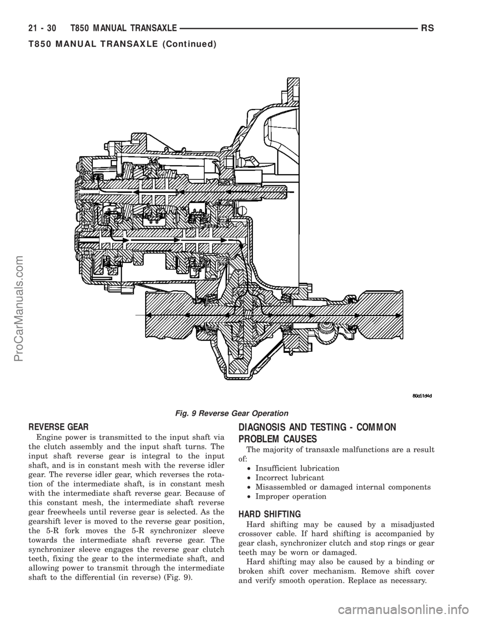
REVERSE GEAR
Engine power is transmitted to the input shaft via
the clutch assembly and the input shaft turns. The
input shaft reverse gear is integral to the input
shaft, and is in constant mesh with the reverse idler
gear. The reverse idler gear, which reverses the rota-
tion of the intermediate shaft, is in constant mesh
with the intermediate shaft reverse gear. Because of
this constant mesh, the intermediate shaft reverse
gear freewheels until reverse gear is selected. As the
gearshift lever is moved to the reverse gear position,
the 5-R fork moves the 5-R synchronizer sleeve
towards the intermediate shaft reverse gear. The
synchronizer sleeve engages the reverse gear clutch
teeth, fixing the gear to the intermediate shaft, and
allowing power to transmit through the intermediate
shaft to the differential (in reverse) (Fig. 9).
DIAGNOSIS AND TESTING - COMMON
PROBLEM CAUSES
The majority of transaxle malfunctions are a result
of:
²Insufficient lubrication
²Incorrect lubricant
²Misassembled or damaged internal components
²Improper operation
HARD SHIFTING
Hard shifting may be caused by a misadjusted
crossover cable. If hard shifting is accompanied by
gear clash, synchronizer clutch and stop rings or gear
teeth may be worn or damaged.
Hard shifting may also be caused by a binding or
broken shift cover mechanism. Remove shift cover
and verify smooth operation. Replace as necessary.
Fig. 9 Reverse Gear Operation
21 - 30 T850 MANUAL TRANSAXLERS
T850 MANUAL TRANSAXLE (Continued)
ProCarManuals.com