Page 1503 of 2177
SPECIFICATIONS - T850 MANUAL TRANSAXLE
GENERAL SPECIFICATIONS
DESCRIPTION SPECIFICATION
Transaxle TypeConstant-mesh, fully synchronized 5-speed with integral
differential
Lubrication MethodSplash oil collected in case passage and oil trough and
distributed to mainshafts via gravity
Fluid Type ATF+4 (Automatic Transmission FluidÐType 9602)
GEAR RATIOS
GEAR RATIO (2.4L Gas) RATIO (2.5L TD)
1st 3.65 3.65
2nd 2.05 2.05
3rd 1.39 1.37
4th 1.03 0.97
5th 0.83 0.76
Reverse 3.47 3.47
Final Drive Ratio 3.77 3.77
Overall Top Gear 3.12 2.67
INPUT SHAFT
BLOCKER RING WEAR GAP
3rd Gear 0.856-1.539 mm (0.0338-0.0606 in.)
4th Gear 0.762-1.631 mm (0.030-0.064 in.)
GEAR END PLAY
3rd Gear 0.099-0.505 mm (0.004-0.020 in.)
4th Gear 0.048-0.457 mm (0.002-0.018 in.)
21 - 56 T850 MANUAL TRANSAXLERS
T850 MANUAL TRANSAXLE (Continued)
ProCarManuals.com
Page 1543 of 2177
ASSEMBLY
NOTE: Depending on date of manufacture, some
input shafts will utilize a needle bearing under the
3rd and 4th Speed Gears.
NOTE: When servicing the input shaft assembly, all
snap rings MUST be replaced with new ones upon
assembly. 5th gear nut must also be replaced.
NOTE: When installing 3/4 synchronizer hub to
shaft, make sure to align oil slots on synchronizer
hub face with oil hole in the shaft splined hub jour-
nal.
NOTE: Refer to (Fig. 215) for input shaft assembly
reference.
Fig. 215 Input Shaft Assembly
1 - INPUT SHAFT 6 - 5TH GEAR NUT
2 - THRUST WASHER 7 - SNAP RING
3 - 3RD GEAR 8 - INPUT BEARING (SEALED)
4 - 4TH GEAR 9 - SNAP RING
5 - 5TH GEAR 10 - 3/4 SYNCHRONIZER
Fig. 214 3rd Gear Removal/Installation
1 - 3RD GEAR
21 - 96 T850 MANUAL TRANSAXLERS
INPUT SHAFT (Continued)
ProCarManuals.com
Page 1544 of 2177
(1) Install input shaft into fixture 8487.
(2) Install thrust washer if removed upon disas-
sembly.
(3) Install 3rd gear and needle bearing (if
equipped) (Fig. 216).
(4) Install 3rd gear blocker ring (Fig. 217).(5) Install 3/4 synchronizer (Fig. 218).When
installing 3/4 synchronizer hub to shaft, make
sure to align oil slots on synchronizer hub face
with oil hole in the shaft splined hub journal.
(6) InstallNEW3/4 synchronizer snap ring (Fig.
219).
Fig. 216 3rd Gear Removal/Installation
1 - 3RD GEAR
Fig. 217 3rd Gear Blocker Ring
1 - 3RD GEAR BLOCKER RING
Fig. 218 3/4 Synchro Assembly
1 - 3/4 SYNCHRONIZER
Fig. 219 3/4 Synchro Snap Ring
1 - SNAP RING
2 - 3/4 SYNCHRONIZER
RST850 MANUAL TRANSAXLE21-97
INPUT SHAFT (Continued)
ProCarManuals.com
Page 1554 of 2177
ASSEMBLY
NOTE: Depending on date of transaxle manufacture,
some intermediate shafts will utilize a needle bear-
ing under 2nd and 5th Speed Gears.
NOTE: Do not re-use snap rings when servicing the
intermediate shaft assembly. Discard snap rings
and install new ones provided with available snap
ring service kit.NOTE: When installing 1/2 & 5/R synchronizers,
make sure to align oil slots on synchronizer hub
face with oil hold in the shaft splined hub journal.
NOTE: Refer to (Fig. 252) for intermediate shaft
assembly reference.
Fig. 252 Intermediate Shaft Assembly
1 - INTERMEDIATE SHAFT 10 - SNAP RING
2 - ROLLER BEARING 11 - SEALED ROLLER BEARING
3 - SNAP RING 12 - THRUST WASHER
4 - NEEDLE BEARING 13 - NEEDLE BEARING
5 - 1ST SPEED GEAR 14 - REVERSE GEAR
6 - SNAP RING 15 - SNAP RING
7 - 2ND SPEED GEAR 16 - 5/R SYNCHRO
8 - 3/4 CLUSTER GEAR 17 - 5TH SPEED GEAR
9 - SNAP RING 18 - 1/2 SYNCHRO
RST850 MANUAL TRANSAXLE21 - 107
INTERMEDIATE SHAFT (Continued)
ProCarManuals.com
Page 1555 of 2177

(1) Press intermediate shaft into NEW roller bear-
ing with arbor press (Fig. 253).
(2) Install intermediate shaft roller bearing snap
ring (Fig. 254).
(3) Install 1st gear roller bearing to intermediate
shaft (Fig. 255).
(4) Install 1st gear to intermediate shaft (Fig.
256).(5) Install 1/2 synchro to fixture 8483. Insert 1st
gear blocker ring, friction cone, and reactor ring as
shown in (Fig. 257).
(6) Install intermediate shaft to synchro assembly
on fixture (Fig. 258).When installing 1/2 synchro-
nizer, make sure to align oil slots on synchro-
nizer hub face with oil hole in the shaft splined
hub journal.Line up friction cone and reactor ring
tabs to gear slots. Remove shaft assembly from fix-
ture.
Fig. 253 Intermediate Shaft Bearing Installation
1 - ARBOR PRESS
2 - INTERMEDIATE SHAFT
3 - CAGED ROLLER BEARING
4 - BEARING SPLITTER
Fig. 254 Intermediate Shaft Roller Bearing Snap
Ring
1 - SNAP RING
Fig. 255 1st Gear Needle Bearing
1 - 1ST GEAR NEEDLE BEARING
Fig. 256 1st Gear Installation
1 - 1ST GEAR
21 - 108 T850 MANUAL TRANSAXLERS
INTERMEDIATE SHAFT (Continued)
ProCarManuals.com
Page 1558 of 2177
(13) InstallNEW3/4 cluster gear snap ring (Fig.
265).
(14) Install 5th gear and needle bearing (if
equipped) to intermediate shaft (Fig. 266).(15) Install 5th gear blocker ring to synchronizer
(Fig. 267).
(16) Install 5th gear synchronizer assembly to
intermediate shaft (Fig. 268).When installing 5/R
synchronizer, make sure to align oil slots on
synchronizer hub face with oil hole in the shaft
splined hub journal.
Fig. 265 3/4 Cluster Gear Snap Ring
1 - SNAP RING
Fig. 266 5th Gear Installation
1 - 5th GEAR
Fig. 267 5th Gear Blocker Ring to Synchro
1 - 5th GEAR BLOCKER RING
2 - 5/R SYNCHRONIZER
Fig. 268 Install 5/R Synchro and 5th Blocker Ring to
5th Gear
1 - 5/R SYNCHRONIZER
2 - 5TH GEAR BLOCKER RING
3 - 5TH GEAR
RST850 MANUAL TRANSAXLE21 - 111
INTERMEDIATE SHAFT (Continued)
ProCarManuals.com
Page 1563 of 2177

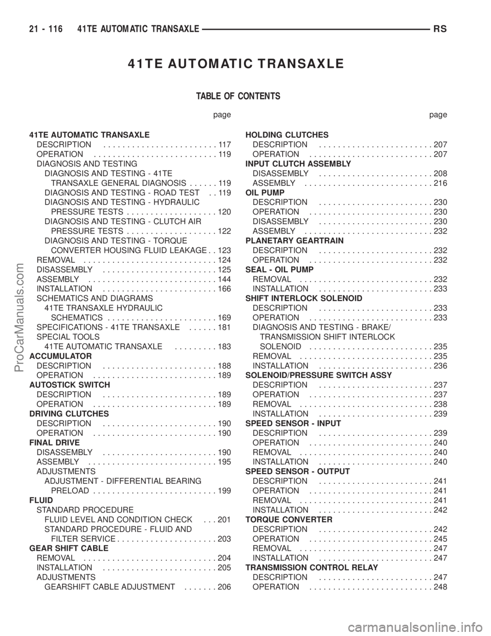
41TE AUTOMATIC TRANSAXLE
TABLE OF CONTENTS
page page
41TE AUTOMATIC TRANSAXLE
DESCRIPTION........................117
OPERATION..........................119
DIAGNOSIS AND TESTING
DIAGNOSIS AND TESTING - 41TE
TRANSAXLE GENERAL DIAGNOSIS......119
DIAGNOSIS AND TESTING - ROAD TEST . . 119
DIAGNOSIS AND TESTING - HYDRAULIC
PRESSURE TESTS...................120
DIAGNOSIS AND TESTING - CLUTCH AIR
PRESSURE TESTS...................122
DIAGNOSIS AND TESTING - TORQUE
CONVERTER HOUSING FLUID LEAKAGE . . 123
REMOVAL............................124
DISASSEMBLY........................125
ASSEMBLY...........................144
INSTALLATION........................166
SCHEMATICS AND DIAGRAMS
41TE TRANSAXLE HYDRAULIC
SCHEMATICS.......................169
SPECIFICATIONS - 41TE TRANSAXLE......181
SPECIAL TOOLS
41TE AUTOMATIC TRANSAXLE.........183
ACCUMULATOR
DESCRIPTION........................188
OPERATION..........................189
AUTOSTICK SWITCH
DESCRIPTION........................189
OPERATION..........................189
DRIVING CLUTCHES
DESCRIPTION........................190
OPERATION..........................190
FINAL DRIVE
DISASSEMBLY........................190
ASSEMBLY...........................195
ADJUSTMENTS
ADJUSTMENT - DIFFERENTIAL BEARING
PRELOAD..........................199
FLUID
STANDARD PROCEDURE
FLUID LEVEL AND CONDITION CHECK . . . 201
STANDARD PROCEDURE - FLUID AND
FILTER SERVICE.....................203
GEAR SHIFT CABLE
REMOVAL............................204
INSTALLATION........................205
ADJUSTMENTS
GEARSHIFT CABLE ADJUSTMENT.......206HOLDING CLUTCHES
DESCRIPTION........................207
OPERATION..........................207
INPUT CLUTCH ASSEMBLY
DISASSEMBLY........................208
ASSEMBLY...........................216
OIL PUMP
DESCRIPTION........................230
OPERATION..........................230
DISASSEMBLY........................230
ASSEMBLY...........................232
PLANETARY GEARTRAIN
DESCRIPTION........................232
OPERATION..........................232
SEAL - OIL PUMP
REMOVAL............................232
INSTALLATION........................233
SHIFT INTERLOCK SOLENOID
DESCRIPTION........................233
OPERATION..........................233
DIAGNOSIS AND TESTING - BRAKE/
TRANSMISSION SHIFT INTERLOCK
SOLENOID..........................235
REMOVAL............................235
INSTALLATION........................236
SOLENOID/PRESSURE SWITCH ASSY
DESCRIPTION........................237
OPERATION..........................237
REMOVAL............................238
INSTALLATION........................239
SPEED SENSOR - INPUT
DESCRIPTION........................239
OPERATION..........................240
REMOVAL............................240
INSTALLATION........................240
SPEED SENSOR - OUTPUT
DESCRIPTION........................241
OPERATION..........................241
REMOVAL............................241
INSTALLATION........................242
TORQUE CONVERTER
DESCRIPTION........................242
OPERATION..........................245
REMOVAL............................247
INSTALLATION........................247
TRANSMISSION CONTROL RELAY
DESCRIPTION........................247
OPERATION..........................248
21 - 116 41TE AUTOMATIC TRANSAXLERS
ProCarManuals.com
Page 1564 of 2177

TRANSMISSION RANGE SENSOR
DESCRIPTION........................248
OPERATION..........................248
REMOVAL............................249
INSTALLATION........................249
TRD LINK
DESCRIPTION........................249
OPERATION..........................249VALVE BODY
DESCRIPTION........................250
OPERATION..........................250
REMOVAL............................251
DISASSEMBLY........................252
ASSEMBLY...........................257
INSTALLATION........................262
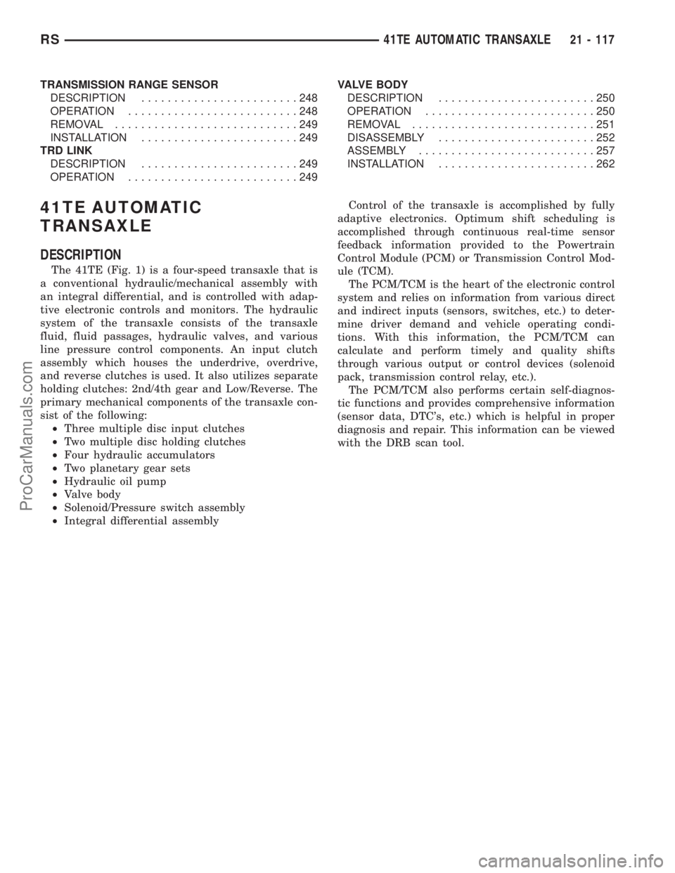
41TE AUTOMATIC
TRANSAXLE
DESCRIPTION
The 41TE (Fig. 1) is a four-speed transaxle that is
a conventional hydraulic/mechanical assembly with
an integral differential, and is controlled with adap-
tive electronic controls and monitors. The hydraulic
system of the transaxle consists of the transaxle
fluid, fluid passages, hydraulic valves, and various
line pressure control components. An input clutch
assembly which houses the underdrive, overdrive,
and reverse clutches is used. It also utilizes separate
holding clutches: 2nd/4th gear and Low/Reverse. The
primary mechanical components of the transaxle con-
sist of the following:
²Three multiple disc input clutches
²Two multiple disc holding clutches
²Four hydraulic accumulators
²Two planetary gear sets
²Hydraulic oil pump
²Valve body
²Solenoid/Pressure switch assembly
²Integral differential assemblyControl of the transaxle is accomplished by fully
adaptive electronics. Optimum shift scheduling is
accomplished through continuous real-time sensor
feedback information provided to the Powertrain
Control Module (PCM) or Transmission Control Mod-
ule (TCM).
The PCM/TCM is the heart of the electronic control
system and relies on information from various direct
and indirect inputs (sensors, switches, etc.) to deter-
mine driver demand and vehicle operating condi-
tions. With this information, the PCM/TCM can
calculate and perform timely and quality shifts
through various output or control devices (solenoid
pack, transmission control relay, etc.).
The PCM/TCM also performs certain self-diagnos-
tic functions and provides comprehensive information
(sensor data, DTC's, etc.) which is helpful in proper
diagnosis and repair. This information can be viewed
with the DRB scan tool.
RS41TE AUTOMATIC TRANSAXLE21 - 117
ProCarManuals.com