2003 CHRYSLER CARAVAN clutch
[x] Cancel search: clutchPage 1611 of 2177
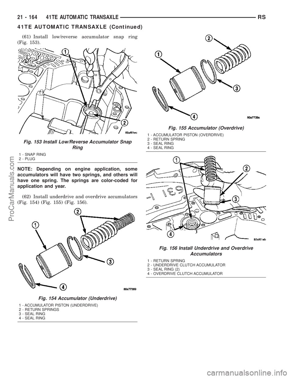
(61) Install low/reverse accumulator snap ring
(Fig. 153).
NOTE: Depending on engine application, some
accumulators will have two springs, and others will
have one spring. The springs are color-coded for
application and year.
(62) Install underdrive and overdrive accumulators
(Fig. 154) (Fig. 155) (Fig. 156).
Fig. 153 Install Low/Reverse Accumulator Snap
Ring
1 - SNAP RING
2 - PLUG
Fig. 154 Accumulator (Underdrive)
1 - ACCUMULATOR PISTON (UNDERDRIVE)
2 - RETURN SPRINGS
3 - SEAL RING
4 - SEAL RING
Fig. 155 Accumulator (Overdrive)
1 - ACCUMULATOR PISTON (OVERDRIVE)
2 - RETURN SPRING
3 - SEAL RING
4 - SEAL RING
Fig. 156 Install Underdrive and Overdrive
Accumulators
1 - RETURN SPRING
2 - UNDERDRIVE CLUTCH ACCUMULATOR
3 - SEAL RING (2)
4 - OVERDRIVE CLUTCH ACCUMULATOR
21 - 164 41TE AUTOMATIC TRANSAXLERS
41TE AUTOMATIC TRANSAXLE (Continued)
ProCarManuals.com
Page 1613 of 2177
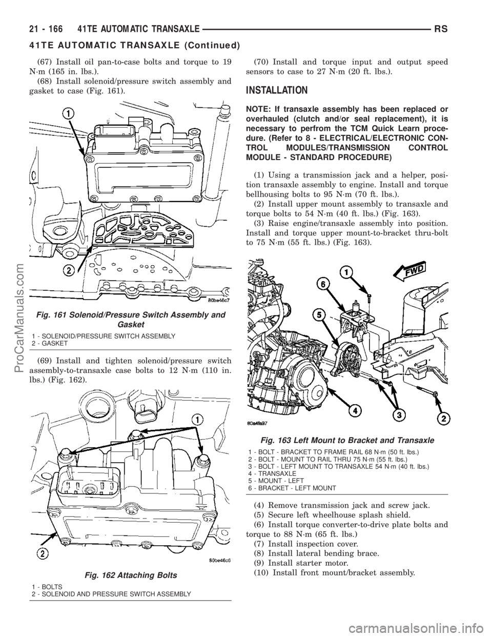
(67) Install oil pan-to-case bolts and torque to 19
N´m (165 in. lbs.).
(68) Install solenoid/pressure switch assembly and
gasket to case (Fig. 161).
(69) Install and tighten solenoid/pressure switch
assembly-to-transaxle case bolts to 12 N´m (110 in.
lbs.) (Fig. 162).(70) Install and torque input and output speed
sensors to case to 27 N´m (20 ft. lbs.).
INSTALLATION
NOTE: If transaxle assembly has been replaced or
overhauled (clutch and/or seal replacement), it is
necessary to perfrom the TCM Quick Learn proce-
dure. (Refer to 8 - ELECTRICAL/ELECTRONIC CON-
TROL MODULES/TRANSMISSION CONTROL
MODULE - STANDARD PROCEDURE)
(1) Using a transmission jack and a helper, posi-
tion transaxle assembly to engine. Install and torque
bellhousing bolts to 95 N´m (70 ft. lbs.).
(2) Install upper mount assembly to transaxle and
torque bolts to 54 N´m (40 ft. lbs.) (Fig. 163).
(3) Raise engine/transaxle assembly into position.
Install and torque upper mount-to-bracket thru-bolt
to 75 N´m (55 ft. lbs.) (Fig. 163).
(4) Remove transmission jack and screw jack.
(5) Secure left wheelhouse splash shield.
(6) Install torque converter-to-drive plate bolts and
torque to 88 N´m (65 ft. lbs.)
(7) Install inspection cover.
(8) Install lateral bending brace.
(9) Install starter motor.
(10) Install front mount/bracket assembly.
Fig. 161 Solenoid/Pressure Switch Assembly and
Gasket
1 - SOLENOID/PRESSURE SWITCH ASSEMBLY
2 - GASKET
Fig. 162 Attaching Bolts
1 - BOLTS
2 - SOLENOID AND PRESSURE SWITCH ASSEMBLY
Fig. 163 Left Mount to Bracket and Transaxle
1 - BOLT - BRACKET TO FRAME RAIL 68 N´m (50 ft. lbs.)
2 - BOLT - MOUNT TO RAIL THRU 75 N´m (55 ft. lbs.)
3 - BOLT - LEFT MOUNT TO TRANSAXLE 54 N´m (40 ft. lbs.)
4 - TRANSAXLE
5 - MOUNT - LEFT
6 - BRACKET - LEFT MOUNT
21 - 166 41TE AUTOMATIC TRANSAXLERS
41TE AUTOMATIC TRANSAXLE (Continued)
ProCarManuals.com
Page 1628 of 2177
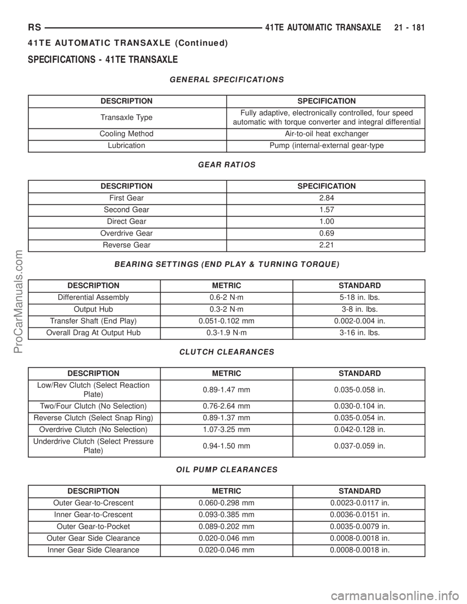
SPECIFICATIONS - 41TE TRANSAXLE
GENERAL SPECIFICATIONS
DESCRIPTION SPECIFICATION
Transaxle TypeFully adaptive, electronically controlled, four speed
automatic with torque converter and integral differential
Cooling Method Air-to-oil heat exchanger
Lubrication Pump (internal-external gear-type
GEAR RATIOS
DESCRIPTION SPECIFICATION
First Gear 2.84
Second Gear 1.57
Direct Gear 1.00
Overdrive Gear 0.69
Reverse Gear 2.21
BEARING SETTINGS (END PLAY & TURNING TORQUE)
DESCRIPTION METRIC STANDARD
Differential Assembly 0.6-2 N´m 5-18 in. lbs.
Output Hub 0.3-2 N´m 3-8 in. lbs.
Transfer Shaft (End Play) 0.051-0.102 mm 0.002-0.004 in.
Overall Drag At Output Hub 0.3-1.9 N´m 3-16 in. lbs.
CLUTCH CLEARANCES
DESCRIPTION METRIC STANDARD
Low/Rev Clutch (Select Reaction
Plate)0.89-1.47 mm 0.035-0.058 in.
Two/Four Clutch (No Selection) 0.76-2.64 mm 0.030-0.104 in.
Reverse Clutch (Select Snap Ring) 0.89-1.37 mm 0.035-0.054 in.
Overdrive Clutch (No Selection) 1.07-3.25 mm 0.042-0.128 in.
Underdrive Clutch (Select Pressure
Plate)0.94-1.50 mm 0.037-0.059 in.
OIL PUMP CLEARANCES
DESCRIPTION METRIC STANDARD
Outer Gear-to-Crescent 0.060-0.298 mm 0.0023-0.0117 in.
Inner Gear-to-Crescent 0.093-0.385 mm 0.0036-0.0151 in.
Outer Gear-to-Pocket 0.089-0.202 mm 0.0035-0.0079 in.
Outer Gear Side Clearance 0.020-0.046 mm 0.0008-0.0018 in.
Inner Gear Side Clearance 0.020-0.046 mm 0.0008-0.0018 in.
RS41TE AUTOMATIC TRANSAXLE21 - 181
41TE AUTOMATIC TRANSAXLE (Continued)
ProCarManuals.com
Page 1629 of 2177
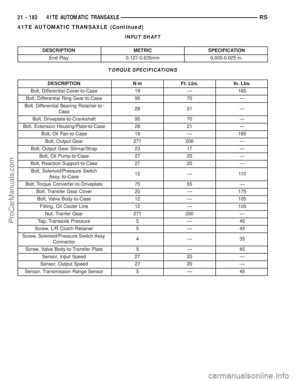
INPUT SHAFT
DESCRIPTION METRIC SPECIFICATION
End Play 0.127-0.635mm 0.005-0.025 in.
TORQUE SPECIFICATIONS
DESCRIPTION N´m Ft. Lbs. In. Lbs.
Bolt, Differential Cover-to-Case 19 Ð 165
Bolt, Differential Ring Gear-to-Case 95 70 Ð
Bolt, Differential Bearing Retainer-to-
Case28 21 Ð
Bolt, Driveplate-to-Crankshaft 95 70 Ð
Bolt, Extension Housing/Plate-to-Case 28 21 Ð
Bolt, Oil Pan-to-Case 19 Ð 165
Bolt, Output Gear 271 200 Ð
Bolt, Output Gear Stirrup/Strap 23 17 Ð
Bolt, Oil Pump-to-Case 27 20 Ð
Bolt, Reaction Support-to-Case 27 20 Ð
Bolt, Solenoid/Pressure Switch
Assy.-to-Case12 Ð 110
Bolt, Torque Converter-to-Driveplate 75 55 Ð
Bolt, Transfer Gear Cover 20 Ð 175
Bolt, Valve Body-to-Case 12 Ð 105
Fitting, Oil Cooler Line 12 Ð 105
Nut, Tranfer Gear 271 200 Ð
Tap, Transaxle Pressure 5 Ð 45
Screw, L/R Clutch Retainer 5 Ð 45
Screw, Solenoid/Pressure Switch Assy.
Connector4Ð35
Screw, Valve Body-to-Transfer Plate 5 Ð 45
Sensor, Input Speed 27 20 Ð
Sensor, Output Speed 27 20 Ð
Sensor, Transmission Range Sensor 5 Ð 45
21 - 182 41TE AUTOMATIC TRANSAXLERS
41TE AUTOMATIC TRANSAXLE (Continued)
ProCarManuals.com
Page 1635 of 2177
ACCUMULATOR
DESCRIPTION
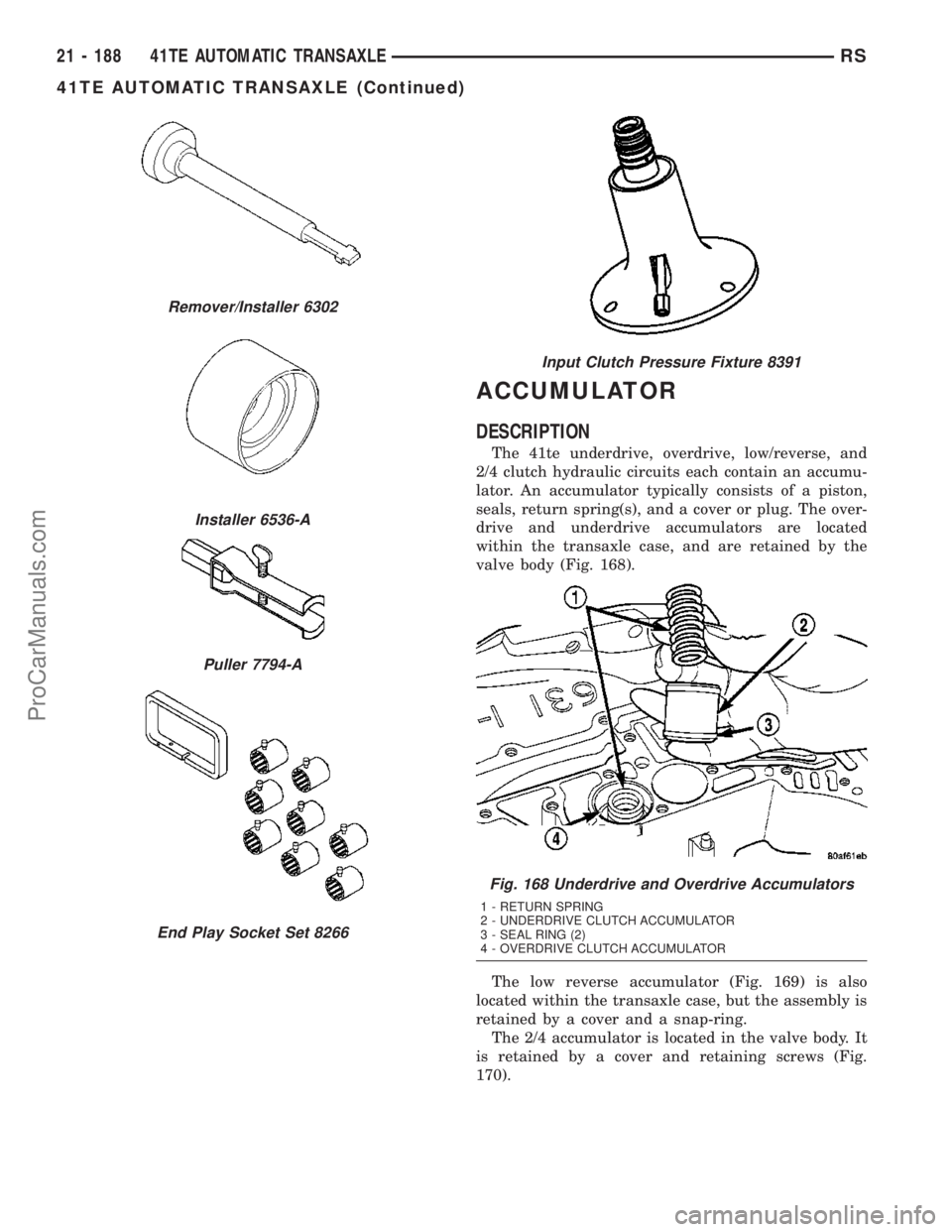
The 41te underdrive, overdrive, low/reverse, and
2/4 clutch hydraulic circuits each contain an accumu-
lator. An accumulator typically consists of a piston,
seals, return spring(s), and a cover or plug. The over-
drive and underdrive accumulators are located
within the transaxle case, and are retained by the
valve body (Fig. 168).
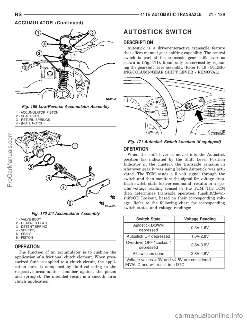
The low reverse accumulator (Fig. 169) is also
located within the transaxle case, but the assembly is
retained by a cover and a snap-ring.
The 2/4 accumulator is located in the valve body. It
is retained by a cover and retaining screws (Fig.
170).
Remover/Installer 6302
Installer 6536-A
Puller 7794-A
End Play Socket Set 8266
Input Clutch Pressure Fixture 8391
Fig. 168 Underdrive and Overdrive Accumulators
1 - RETURN SPRING
2 - UNDERDRIVE CLUTCH ACCUMULATOR
3 - SEAL RING (2)
4 - OVERDRIVE CLUTCH ACCUMULATOR
21 - 188 41TE AUTOMATIC TRANSAXLERS
41TE AUTOMATIC TRANSAXLE (Continued)
ProCarManuals.com
Page 1636 of 2177
OPERATION
The function of an accumulator is to cushion the
application of a frictional clutch element. When pres-
surized fluid is applied to a clutch circuit, the appli-
cation force is dampened by fluid collecting in the
respective accumulator chamber against the piston
and spring(s). The intended result is a smooth, firm
clutch application.
AUTOSTICK SWITCH
DESCRIPTION
Autostick is a driver-interactive transaxle feature
that offers manual gear shifting capability. The control
switch is part of the transaxle gear shift lever as
shown in (Fig. 171). It can only be serviced by replac-
ing the gearshift lever assembly. (Refer to 19 - STEER-
ING/COLUMN/GEAR SHIFT LEVER - REMOVAL)
OPERATION
When the shift lever is moved into the Autostick
position (as indicated by the Shift Lever Position
Indicator in the cluster), the transaxle remains in
whatever gear it was using before Autostick was acti-
vated. The TCM sends a 5 volt signal through the
switch and then monitors the signal for voltage drop.
Each switch state (driver command) results in a spe-
cific voltage reading sensed by the TCM. The TCM
then determines transaxle operation (upshift/down-
shift/OD Lockout) based on their corresponding volt-
age. Refer to the following chart for corresponding
switch states and voltage readings:
Switch State Voltage Reading
Autostick DOWN
depressed0.3V-1.6V
Autostick UP depressed 1.6V-2.8V
Overdrive OFF9Lockout9
depressed2.8V-3.8V
All switches open 3.8V-4.8V
-Voltage values <.3V and >4.8V are considered
INVALID and will result in a DTC
Fig. 169 Low/Reverse Accumulator Assembly
1 - ACCUMULATOR PISTON
2 - SEAL RINGS
3 - RETURN SPRINGS
4 - (NOTE NOTCH)
Fig. 170 2/4 Accumulator Assembly
1 - VALVE BODY
2 - RETAINER PLATE
3 - DETENT SPRING
4 - SPRINGS
5 - SEALS
6 - PISTON
Fig. 171 Autostick Switch Location (if equipped)
RS41TE AUTOMATIC TRANSAXLE21 - 189
ACCUMULATOR (Continued)
ProCarManuals.com
Page 1637 of 2177
Moving the switch up causes an upshift and moving
the switch down causes a downshift. The instrument
cluster will illuminate the selected gear. The vehicle
can be launched in 1st, 2nd, or 3rd gear while in the
Autostick mode. The speed control is operable in 3rd
and 4th gear Autostick mode. Speed control will be
deactivated if the transaxle is shifted to 2nd gear.
Shifting into OD position cancels the Autostick mode,
and the transaxle resumes the OD shift schedule.
DRIVING CLUTCHES
DESCRIPTION
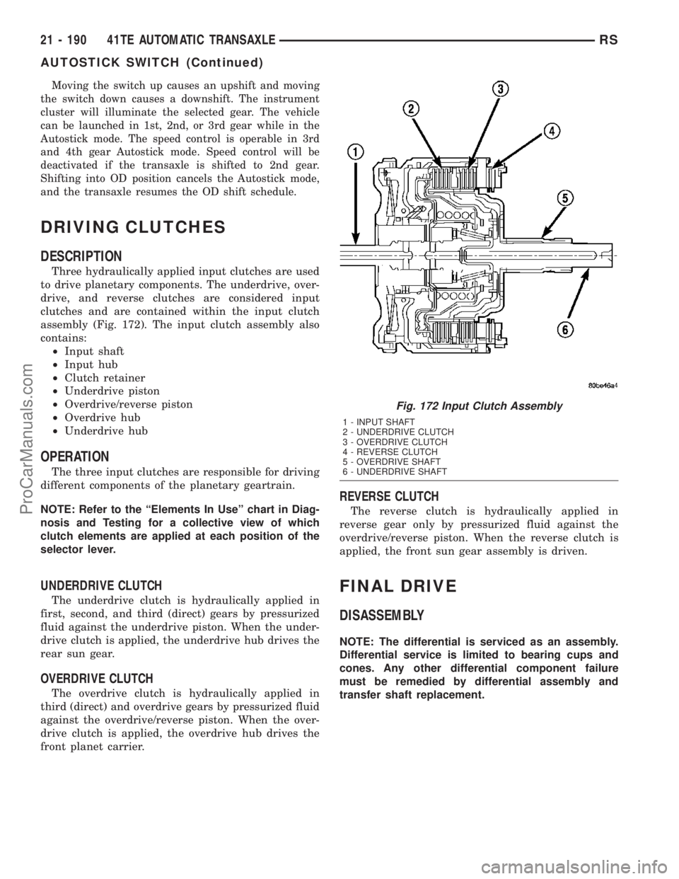
Three hydraulically applied input clutches are used
to drive planetary components. The underdrive, over-
drive, and reverse clutches are considered input
clutches and are contained within the input clutch
assembly (Fig. 172). The input clutch assembly also
contains:
²Input shaft
²Input hub
²Clutch retainer
²Underdrive piston
²Overdrive/reverse piston
²Overdrive hub
²Underdrive hub
OPERATION
The three input clutches are responsible for driving
different components of the planetary geartrain.
NOTE: Refer to the ªElements In Useº chart in Diag-
nosis and Testing for a collective view of which
clutch elements are applied at each position of the
selector lever.
UNDERDRIVE CLUTCH
The underdrive clutch is hydraulically applied in
first, second, and third (direct) gears by pressurized
fluid against the underdrive piston. When the under-
drive clutch is applied, the underdrive hub drives the
rear sun gear.
OVERDRIVE CLUTCH
The overdrive clutch is hydraulically applied in
third (direct) and overdrive gears by pressurized fluid
against the overdrive/reverse piston. When the over-
drive clutch is applied, the overdrive hub drives the
front planet carrier.
REVERSE CLUTCH
The reverse clutch is hydraulically applied in
reverse gear only by pressurized fluid against the
overdrive/reverse piston. When the reverse clutch is
applied, the front sun gear assembly is driven.
FINAL DRIVE
DISASSEMBLY
NOTE: The differential is serviced as an assembly.
Differential service is limited to bearing cups and
cones. Any other differential component failure
must be remedied by differential assembly and
transfer shaft replacement.
Fig. 172 Input Clutch Assembly
1 - INPUT SHAFT
2 - UNDERDRIVE CLUTCH
3 - OVERDRIVE CLUTCH
4 - REVERSE CLUTCH
5 - OVERDRIVE SHAFT
6 - UNDERDRIVE SHAFT
21 - 190 41TE AUTOMATIC TRANSAXLERS
AUTOSTICK SWITCH (Continued)
ProCarManuals.com
Page 1649 of 2177
(3) Select sensors.
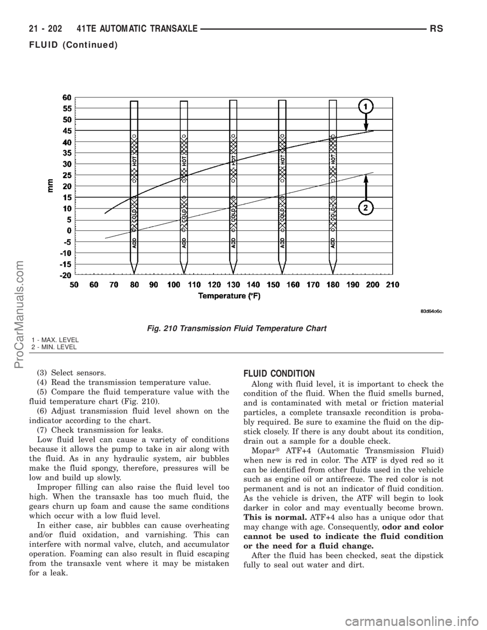
(4) Read the transmission temperature value.
(5) Compare the fluid temperature value with the
fluid temperature chart (Fig. 210).
(6) Adjust transmission fluid level shown on the
indicator according to the chart.
(7) Check transmission for leaks.
Low fluid level can cause a variety of conditions
because it allows the pump to take in air along with
the fluid. As in any hydraulic system, air bubbles
make the fluid spongy, therefore, pressures will be
low and build up slowly.
Improper filling can also raise the fluid level too
high. When the transaxle has too much fluid, the
gears churn up foam and cause the same conditions
which occur with a low fluid level.
In either case, air bubbles can cause overheating
and/or fluid oxidation, and varnishing. This can
interfere with normal valve, clutch, and accumulator
operation. Foaming can also result in fluid escaping
from the transaxle vent where it may be mistaken
for a leak.FLUID CONDITION
Along with fluid level, it is important to check the
condition of the fluid. When the fluid smells burned,
and is contaminated with metal or friction material
particles, a complete transaxle recondition is proba-
bly required. Be sure to examine the fluid on the dip-
stick closely. If there is any doubt about its condition,
drain out a sample for a double check.
MopartATF+4 (Automatic Transmission Fluid)
when new is red in color. The ATF is dyed red so it
can be identified from other fluids used in the vehicle
such as engine oil or antifreeze. The red color is not
permanent and is not an indicator of fluid condition.
As the vehicle is driven, the ATF will begin to look
darker in color and may eventually become brown.
This is normal.ATF+4 also has a unique odor that
may change with age. Consequently,odor and color
cannot be used to indicate the fluid condition
or the need for a fluid change.
After the fluid has been checked, seat the dipstick
fully to seal out water and dirt.
Fig. 210 Transmission Fluid Temperature Chart
1 - MAX. LEVEL
2 - MIN. LEVEL
21 - 202 41TE AUTOMATIC TRANSAXLERS
FLUID (Continued)
ProCarManuals.com