Page 1575 of 2177
(9) Using a screwdriver, push park rod rollers
away from guide bracket (Fig. 20) and remove valve
body assembly (Fig. 21).
NOTE: Depending on engine application, some
accumulators will have two springs and others will
have one spring. The springs are color-coded
according to application and year. When disassem-
bling, mark accumulator spring location to ease
assembly.(10) Remove underdrive and overdrive accumula-
tors (Fig. 22) (Fig. 23) (Fig. 24).
Fig. 20 Push Park Rod Rollers from Guide Bracket
1 - PARK SPRAG ROLLERS
2 - SCREWDRIVER
3 - PARK SPRAG GUIDE BRACKET
Fig. 21 Remove Valve Body
1 - VALVE BODY
Fig. 22 Remove Underdrive and Overdrive
Accumulators
1 - RETURN SPRING
2 - UNDERDRIVE CLUTCH ACCUMULATOR
3 - SEAL RING (2)
4 - OVERDRIVE CLUTCH ACCUMULATOR
Fig. 23 Accumulator (Underdrive)
1 - ACCUMULATOR PISTON (UNDERDRIVE)
2 - RETURN SPRINGS
3 - SEAL RING
4 - SEAL RING
21 - 128 41TE AUTOMATIC TRANSAXLERS
41TE AUTOMATIC TRANSAXLE (Continued)
ProCarManuals.com
Page 1579 of 2177
(21) Remove #1 needle bearing (Fig. 36).
(22) Remove input clutch assembly (Fig. 37).(23) Remove #4 thrust plate (Fig. 38).
(24) Remove front sun gear assembly and #4
thrust washer (Fig. 39).
Fig. 36 Remove Caged Needle Bearing
1 - #1 CAGED NEEDLE BEARING
2 - NOTE: TANGED SIDE OUT
Fig. 37 Remove Input Clutch Assembly
1 - INPUT CLUTCH ASSEMBLY
2 - #4 THRUST WASHER
Fig. 38 No. 4 Thrust Plate
1 - OVERDRIVE SHAFT ASSEMBLY
2 - #4 THRUST PLATE (SELECT)
3 - 3 DABS OF PETROLATUM FOR RETENTION
Fig. 39 Remove Front Sun Gear Assembly
1 - FRONT SUN GEAR ASSEMBLY
2 - #4 THRUST WASHER (FOUR TABS)
21 - 132 41TE AUTOMATIC TRANSAXLERS
41TE AUTOMATIC TRANSAXLE (Continued)
ProCarManuals.com
Page 1580 of 2177

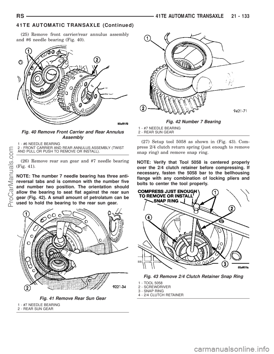
(25) Remove front carrier/rear annulus assembly
and #6 needle bearing (Fig. 40).
(26) Remove rear sun gear and #7 needle bearing
(Fig. 41).
NOTE: The number 7 needle bearing has three anti-
reversal tabs and is common with the number five
and number two position. The orientation should
allow the bearing to seat flat against the rear sun
gear (Fig. 42). A small amount of petrolatum can be
used to hold the bearing to the rear sun gear.(27) Setup tool 5058 as shown in (Fig. 43). Com-
press 2/4 clutch return spring (just enough to remove
snap ring) and remove snap ring.
NOTE: Verify that Tool 5058 is centered properly
over the 2/4 clutch retainer before compressing. If
necessary, fasten the 5058 bar to the bellhousing
flange with any combination of locking pliers and
bolts to center the tool properly.
Fig. 40 Remove Front Carrier and Rear Annulus
Assembly
1 - #6 NEEDLE BEARING
2 - FRONT CARRIER AND REAR ANNULUS ASSEMBLY (TWIST
AND PULL OR PUSH TO REMOVE OR INSTALL).
Fig. 41 Remove Rear Sun Gear
1 - #7 NEEDLE BEARING
2 - REAR SUN GEAR
Fig. 42 Number 7 Bearing
1 - #7 NEEDLE BEARING
2 - REAR SUN GEAR
Fig. 43 Remove 2/4 Clutch Retainer Snap Ring
1 - TOOL 5058
2 - SCREWDRIVER
3 - SNAP RING
4 - 2/4 CLUTCH RETAINER
RS41TE AUTOMATIC TRANSAXLE21 - 133
41TE AUTOMATIC TRANSAXLE (Continued)
ProCarManuals.com
Page 1581 of 2177
(28) Remove 2/4 clutch retainer (Fig. 44).
(29) Remove 2/4 clutch return spring (Fig. 45).(30) Remove 2/4 clutch pack (Fig. 46).Tag 2/4
clutch pack for reassembly identification.
(31) Remove tapered snap ring (Fig. 47).
Fig. 44 2/4 Clutch Retainer
1 - 2/4 CLUTCH RETAINER
2 - 2/4 CLUTCH RETURN SPRING
Fig. 45 Remove 2/4 Clutch Return Spring
1 - 2/4 CLUTCH RETURN SPRING
Fig. 46 Remove 2/4 Clutch Pack
1 - CLUTCH PLATE (4)
2 - CLUTCH DISC (4)
Fig. 47 Remove Tapered Snap Ring
1 - LOW/REVERSE CLUTCH REACTION PLATE
2 - SCREWDRIVER
3 - LOW/REVERSE TAPERED SNAP RING (TAPERED SIDE UP)
4 - OIL PAN FACE
5 - LONG TAB
21 - 134 41TE AUTOMATIC TRANSAXLERS
41TE AUTOMATIC TRANSAXLE (Continued)
ProCarManuals.com
Page 1582 of 2177
(32) Remove low/reverse reaction plate (Fig. 48).
(33) Remove one low/reverse clutch disc (Fig. 49).(34) Remove low/reverse reaction plate snap ring
(Fig. 50).
(35) Remove low/reverse clutch pack (Fig. 51).
Fig. 48 Remove Low/Reverse Reaction Plate
1 - LOW/REVERSE REACTION PLATE (FLAT SIDE UP)
Fig. 49 Remove One Disc
1 - ONE DISC FROM LOW/REVERSE CLUTCH
Fig. 50 Remove Low/Reverse Reaction Plate Snap
Ring
1 - SCREWDRIVER
2 - LOW/REVERSE REACTION PLATE FLAT SNAP RING
3 - DO NOT SCRATCH CLUTCH PLATE
Fig. 51 Remove Low/Reverse Clutch Pack
1 - CLUTCH PLATES (5)
2 - CLUTCH DISCS (5)
RS41TE AUTOMATIC TRANSAXLE21 - 135
41TE AUTOMATIC TRANSAXLE (Continued)
ProCarManuals.com
Page 1588 of 2177
(55) Remove rear carrier assembly from transaxle
(Fig. 72).
(56) Remove rear carrier assembly bearing cone
using setup shown in (Fig. 73).(57) Install low/reverse spring compressor tool as
shown in (Fig. 74) (Fig. 75).
Fig. 72 Remove Rear Carrier Assembly
1 - REAR CARRIER ASSEMBLY
Fig. 73 Remove Rear Carrier Bearing Cone
1 - TOOL 5048 WITH JAWS 5048±3 AND BUTTON 6055
2 - WRENCHES
3 - REAR CARRIER ASSEMBLY
Fig. 74 Low/Reverse Spring Compressor Tool
1 - TOOL 6057
2 - TOOL 5059
3 - TOOL 5058±3
Fig. 75 Compressor Tool in Use
1 - LOW/REVERSE CLUTCH RETURN SPRING
2 - SNAP RING (INSTALL AS SHOWN)
3 - TOOL 6057
4 - TOOL 5059
5 - TOOL 5058±3
RS41TE AUTOMATIC TRANSAXLE21 - 141
41TE AUTOMATIC TRANSAXLE (Continued)
ProCarManuals.com
Page 1590 of 2177
(62) Inspect guide bracket components for exces-
sive wear and replace if necessary (Fig. 80).
(63) Remove low/reverse clutch piston (Fig. 81).(64) Remove low/reverse piston retainer-to-case
screws (Fig. 82).
(65) Remove low/reverse piston retainer (Fig. 83).
Fig. 80 Guide Bracket Disassembled
1 - ANTIRATCHET SPRING
2 - GUIDE BRACKET
3 - SPLIT SLEEVE
4 - SPACER
5-PAWL
6 - STEPPED SPACER
Fig. 81 Remove Low/Reverse Clutch Piston
1 - LOW/REVERSE CLUTCH PISTON
2 - D-RING SEAL
3 - D-RING SEAL
Fig. 82 Remove Piston Retainer Attaching Screws
1 - LOW/REVERSE CLUTCH PISTON RETAINER
2 - SCREWDRIVER
3 - TORX-LOC SCREWS
Fig. 83 Remove Piston Retainer
1 - LOW/REVERSE CLUTCH PISTON RETAINER
2 - GASKET
RS41TE AUTOMATIC TRANSAXLE21 - 143
41TE AUTOMATIC TRANSAXLE (Continued)
ProCarManuals.com
Page 1591 of 2177

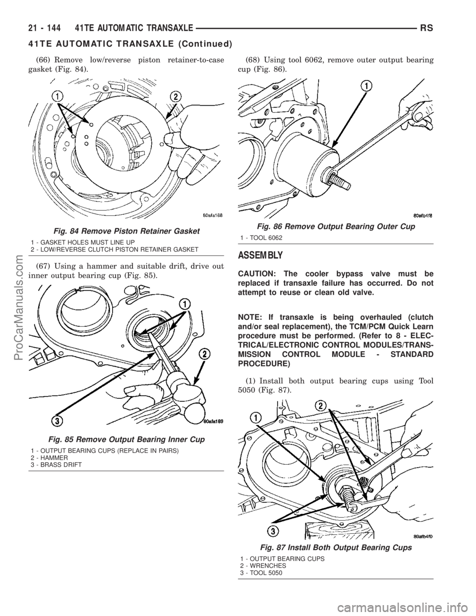
(66) Remove low/reverse piston retainer-to-case
gasket (Fig. 84).
(67) Using a hammer and suitable drift, drive out
inner output bearing cup (Fig. 85).(68) Using tool 6062, remove outer output bearing
cup (Fig. 86).
ASSEMBLY
CAUTION: The cooler bypass valve must be
replaced if transaxle failure has occurred. Do not
attempt to reuse or clean old valve.
NOTE: If transaxle is being overhauled (clutch
and/or seal replacement), the TCM/PCM Quick Learn
procedure must be performed. (Refer to 8 - ELEC-
TRICAL/ELECTRONIC CONTROL MODULES/TRANS-
MISSION CONTROL MODULE - STANDARD
PROCEDURE)
(1) Install both output bearing cups using Tool
5050 (Fig. 87).
Fig. 84 Remove Piston Retainer Gasket
1 - GASKET HOLES MUST LINE UP
2 - LOW/REVERSE CLUTCH PISTON RETAINER GASKET
Fig. 85 Remove Output Bearing Inner Cup
1 - OUTPUT BEARING CUPS (REPLACE IN PAIRS)
2 - HAMMER
3 - BRASS DRIFT
Fig. 86 Remove Output Bearing Outer Cup
1 - TOOL 6062
Fig. 87 Install Both Output Bearing Cups
1 - OUTPUT BEARING CUPS
2 - WRENCHES
3 - TOOL 5050
21 - 144 41TE AUTOMATIC TRANSAXLERS
41TE AUTOMATIC TRANSAXLE (Continued)
ProCarManuals.com