Page 1670 of 2177

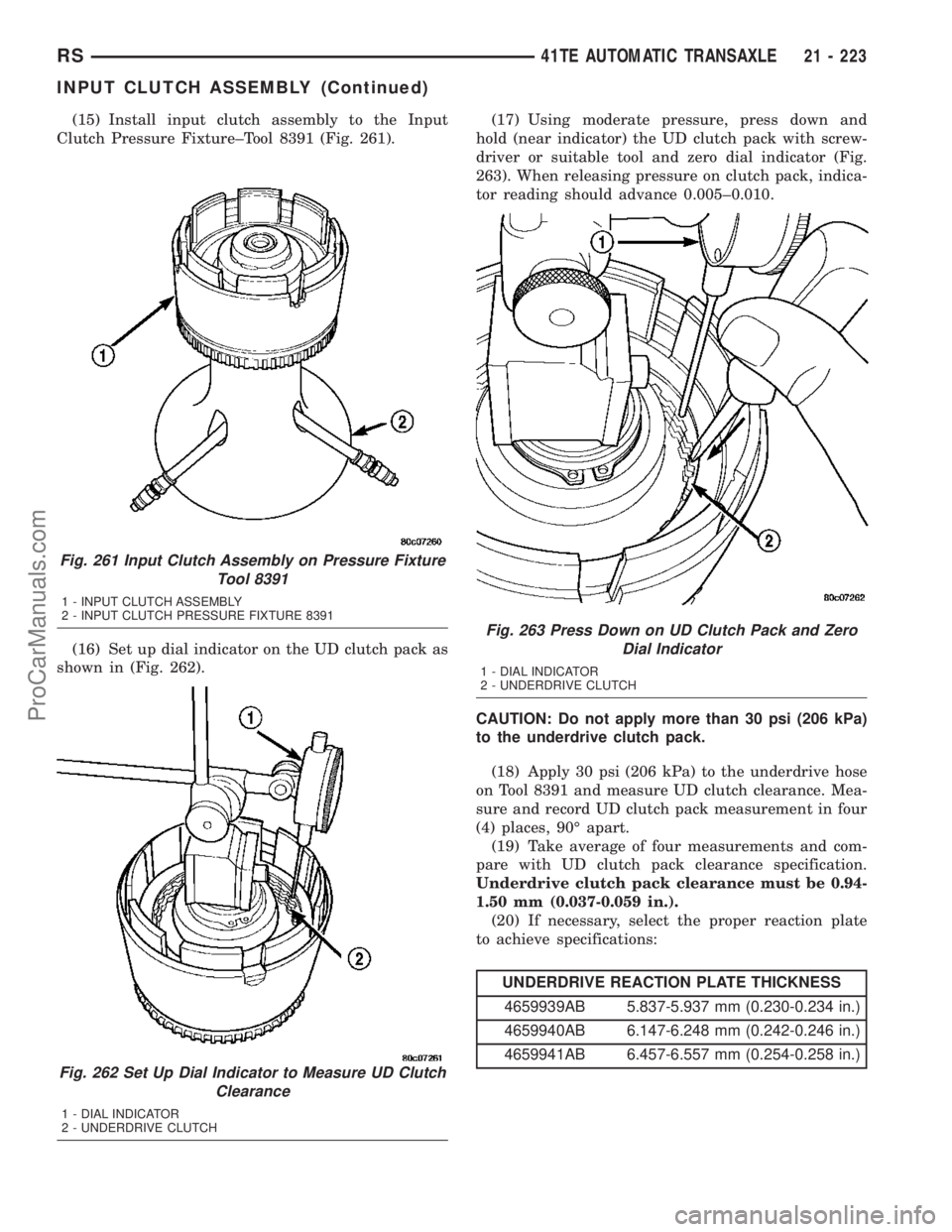
(15) Install input clutch assembly to the Input
Clutch Pressure Fixture±Tool 8391 (Fig. 261).
(16) Set up dial indicator on the UD clutch pack as
shown in (Fig. 262).(17) Using moderate pressure, press down and
hold (near indicator) the UD clutch pack with screw-
driver or suitable tool and zero dial indicator (Fig.
263). When releasing pressure on clutch pack, indica-
tor reading should advance 0.005±0.010.
CAUTION: Do not apply more than 30 psi (206 kPa)
to the underdrive clutch pack.
(18) Apply 30 psi (206 kPa) to the underdrive hose
on Tool 8391 and measure UD clutch clearance. Mea-
sure and record UD clutch pack measurement in four
(4) places, 90É apart.
(19) Take average of four measurements and com-
pare with UD clutch pack clearance specification.
Underdrive clutch pack clearance must be 0.94-
1.50 mm (0.037-0.059 in.).
(20) If necessary, select the proper reaction plate
to achieve specifications:
UNDERDRIVE REACTION PLATE THICKNESS
4659939AB 5.837-5.937 mm (0.230-0.234 in.)
4659940AB 6.147-6.248 mm (0.242-0.246 in.)
4659941AB 6.457-6.557 mm (0.254-0.258 in.)
Fig. 261 Input Clutch Assembly on Pressure Fixture
Tool 8391
1 - INPUT CLUTCH ASSEMBLY
2 - INPUT CLUTCH PRESSURE FIXTURE 8391
Fig. 262 Set Up Dial Indicator to Measure UD Clutch
Clearance
1 - DIAL INDICATOR
2 - UNDERDRIVE CLUTCH
Fig. 263 Press Down on UD Clutch Pack and Zero
Dial Indicator
1 - DIAL INDICATOR
2 - UNDERDRIVE CLUTCH
RS41TE AUTOMATIC TRANSAXLE21 - 223
INPUT CLUTCH ASSEMBLY (Continued)
ProCarManuals.com
Page 1671 of 2177
(21) Install the OD clutch pack (four frictions/three
steels) (Fig. 264).
(22) Install OD pressure plate waved snap ring
(Fig. 265).(23) Install the OD/Reverse pressure plate with
large step down (towards OD clutch pack) (Fig. 266).
(24) Install OD pressure plate flat snap ring (Fig.
267) (Fig. 268).
Fig. 264 Install OD Clutch Pack
1 - OVERDRIVE CLUTCH PACK
Fig. 265 Install Waved Snap Ring
1 - OVERDRIVE PRESSURE PLATE WAVED SNAP RING
2 - SCREWDRIVER
Fig. 266 OD/Reverse Pressure Plate
1 - OVERDRIVE/REVERSE PRESSURE PLATE
2 - (STEP SIDE DOWN)
Fig. 267 Install Flat Snap Ring
1 - ARBOR PRESS RAM
2 - TOOL 5059A
3 - FLAT SNAP RING
21 - 224 41TE AUTOMATIC TRANSAXLERS
INPUT CLUTCH ASSEMBLY (Continued)
ProCarManuals.com
Page 1672 of 2177
(25) Measure OD clutch pack clearance. Set up
dial indicator on top of the OD/Reverse pressure
plate as shown in (Fig. 269).
Fig. 268 Overdrive Clutch Assembly
1 - SNAP RING
2 - OD/REVERSE PRESSURE PLATE
3 - SNAP RING (WAVE)4 - CLUTCH DISC (4)
5 - CLUTCH STEEL (3)
6 - INPUT CLUTCH ASSEMBLY
RS41TE AUTOMATIC TRANSAXLE21 - 225
INPUT CLUTCH ASSEMBLY (Continued)
ProCarManuals.com
Page 1673 of 2177

(26) Zero dial indicator and apply 30 psi (206 kPa)
air pressure to the overdrive clutch hose on Tool
8391. Measure and record OD clutch pack measure-
ment in four (4) places, 90É apart.
(27) Take average of four measurements and com-
pare with OD clutch pack clearance specification.
The overdrive (OD) clutch pack clearance is
1.07-3.25 mm (0.042-0.128 in.).
If not within specifications, the clutch is not
assembled properly. There is no adjustment for the
OD clutch clearance.
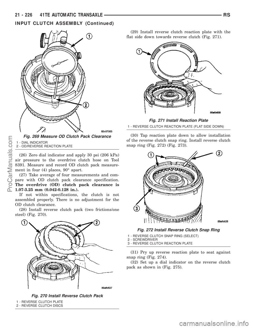
(28) Install reverse clutch pack (two frictions/one
steel) (Fig. 270).(29) Install reverse clutch reaction plate with the
flat side down towards reverse clutch (Fig. 271).
(30) Tap reaction plate down to allow installation
of the reverse clutch snap ring. Install reverse clutch
snap ring (Fig. 272) (Fig. 273).
(31) Pry up reverse reaction plate to seat against
snap ring (Fig. 274).
(32) Set up a dial indicator on the reverse clutch
pack as shown in (Fig. 275).
Fig. 269 Measure OD Clutch Pack Clearance
1 - DIAL INDICATOR
2 - OD/REVERSE REACTION PLATE
Fig. 270 Install Reverse Clutch Pack
1 - REVERSE CLUTCH PLATE
2 - REVERSE CLUTCH DISCS
Fig. 271 Install Reaction Plate
1 - REVERSE CLUTCH REACTION PLATE (FLAT SIDE DOWN)
Fig. 272 Install Reverse Clutch Snap Ring
1 - REVERSE CLUTCH SNAP RING (SELECT)
2 - SCREWDRIVER
3 - REVERSE CLUTCH REACTION PLATE
21 - 226 41TE AUTOMATIC TRANSAXLERS
INPUT CLUTCH ASSEMBLY (Continued)
ProCarManuals.com
Page 1674 of 2177
Fig. 273 Reverse Clutch Assembly
1 - SNAP RING
2 - REACTION PLATE
3 - CLUTCH DISC (2)4 - CLUTCH PLATE (1)
5 - INPUT CLUTCH ASSEMBLY
Fig. 274 Pry Up Reaction Plate to Seat Against Snap
Ring
1 - SCREWDRIVER
2 - SNAP RING
3 - SCREWDRIVER
4 - MUST RAISE REVERSE REACTION PLATE TO RAISE SNAP
RING
Fig. 275 Measure Reverse Clutch Pack Clearance
1 - DIAL INDICATOR
2 - REVERSE CLUTCH
RS41TE AUTOMATIC TRANSAXLE21 - 227
INPUT CLUTCH ASSEMBLY (Continued)
ProCarManuals.com
Page 1675 of 2177

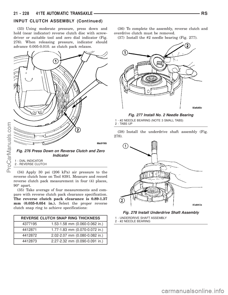
(33) Using moderate pressure, press down and
hold (near indicator) reverse clutch disc with screw-
driver or suitable tool and zero dial indicator (Fig.
276). When releasing pressure, indicator should
advance 0.005-0.010. as clutch pack relaxes.
(34) Apply 30 psi (206 kPa) air pressure to the
reverse clutch hose on Tool 8391. Measure and record
reverse clutch pack measurement in four (4) places,
90É apart.
(35) Take average of four measurements and com-
pare with reverse clutch pack clearance specification.
The reverse clutch pack clearance is 0.89-1.37
mm (0.035-0.054 in.).Select the proper reverse
clutch snap ring to achieve specifications:
REVERSE CLUTCH SNAP RING THICKNESS
4377195 1.53-1.58 mm (0.060-0.062 in.)
4412871 1.77-1.83 mm (0.070-0.072 in.)
4412872 2.02-2.07 mm (0.080-0.082 in.)
4412873 2.27-2.32 mm (0.090-0.091 in.)(36) To complete the assembly, reverse clutch and
overdrive clutch must be removed.
(37) Install the #2 needle bearing (Fig. 277).
(38) Install the underdrive shaft assembly (Fig.
278).
Fig. 276 Press Down on Reverse Clutch and Zero
Indicator
1 - DIAL INDICATOR
2 - REVERSE CLUTCH
Fig. 277 Install No. 2 Needle Bearing
1 - #2 NEEDLE BEARING (NOTE 3 SMALL TABS)
2 - TABS UP
Fig. 278 Install Underdrive Shaft Assembly
1 - UNDERDRIVE SHAFT ASSEMBLY
2 - #2 NEEDLE BEARING
21 - 228 41TE AUTOMATIC TRANSAXLERS
INPUT CLUTCH ASSEMBLY (Continued)
ProCarManuals.com
Page 1676 of 2177
(39) Install the #3 thrust washer to the underdrive
shaft assembly. Be sure five tabs are seated properly
(Fig. 279).
(40) Install the #3 thrust plate to the bottom of the
overdrive shaft assembly. Retain with petrolatum or
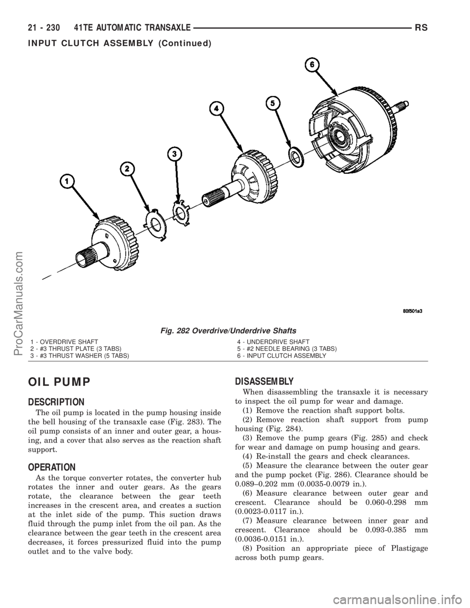
transmission assembly gel (Fig. 280).(41) Install the overdrive shaft assembly (Fig. 281)
(Fig. 282).
(42) Reinstall overdrive and reverse clutch as
shown.Rechecking these clutch clearances is
not necessary.
Fig. 279 Install No. 3 Thrust Washer
1 - #3 THRUST WASHER (NOTE 5 TABS)
2 - UNDERDRIVE SHAFT ASSEMBLY
Fig. 280 Install No. 3 Thrust Plate
1 - OVERDRIVE SHAFT ASSEMBLY
2 - DABS OF PETROLATUM (FOR RETENTION)
3 - #3 THRUST PLATE (NOTE 3 TABS)
Fig. 281 Install Overdrive Shaft Assembly
1 - OVERDRIVE SHAFT ASSEMBLY
2 - #3 THRUST PLATE
3 - #3 THRUST WASHER
RS41TE AUTOMATIC TRANSAXLE21 - 229
INPUT CLUTCH ASSEMBLY (Continued)
ProCarManuals.com
Page 1677 of 2177

OIL PUMP
DESCRIPTION
The oil pump is located in the pump housing inside
the bell housing of the transaxle case (Fig. 283). The
oil pump consists of an inner and outer gear, a hous-
ing, and a cover that also serves as the reaction shaft
support.
OPERATION
As the torque converter rotates, the converter hub
rotates the inner and outer gears. As the gears
rotate, the clearance between the gear teeth
increases in the crescent area, and creates a suction
at the inlet side of the pump. This suction draws
fluid through the pump inlet from the oil pan. As the
clearance between the gear teeth in the crescent area
decreases, it forces pressurized fluid into the pump
outlet and to the valve body.
DISASSEMBLY
When disassembling the transaxle it is necessary
to inspect the oil pump for wear and damage.
(1) Remove the reaction shaft support bolts.
(2) Remove reaction shaft support from pump
housing (Fig. 284).
(3) Remove the pump gears (Fig. 285) and check
for wear and damage on pump housing and gears.
(4) Re-install the gears and check clearances.
(5) Measure the clearance between the outer gear
and the pump pocket (Fig. 286). Clearance should be
0.089±0.202 mm (0.0035-0.0079 in.).
(6) Measure clearance between outer gear and
crescent. Clearance should be 0.060-0.298 mm
(0.0023-0.0117 in.).
(7) Measure clearance between inner gear and
crescent. Clearance should be 0.093-0.385 mm
(0.0036-0.0151 in.).
(8) Position an appropriate piece of Plastigage
across both pump gears.
Fig. 282 Overdrive/Underdrive Shafts
1 - OVERDRIVE SHAFT
2 - #3 THRUST PLATE (3 TABS)
3 - #3 THRUST WASHER (5 TABS)4 - UNDERDRIVE SHAFT
5 - #2 NEEDLE BEARING (3 TABS)
6 - INPUT CLUTCH ASSEMBLY
21 - 230 41TE AUTOMATIC TRANSAXLERS
INPUT CLUTCH ASSEMBLY (Continued)
ProCarManuals.com