Page 406 of 492
Follow these instructions to lower the spare tire:
1. Your vehicle may be equipped with a hoist lock (J).
Open the spare tire lock cover on the bumper and
use the ignition key to remove the lock.
2. Assemble the wheel wrench (H) and the two jack
handle extensions (I) as shown.3. Insert the hoist end
(open end) (F) of the
extension through
the hole (G) in the rear
bumper.
Be sure the hoist end of the extension connects to
the hoist shaft (E). The ribbed square end of the
extension is used to lower the spare tire.
4. Turn the wheel wrench (H) counterclockwise to
lower the spare tire to the ground. Continue to
turn the wheel wrench until the spare tire can be
pulled out from under the vehicle.
If the spare tire does not lower to the ground, the
secondary latch is engaged causing the tire
not to lower. See ªSecondary Latch Systemº later in
this section.
5-73
Page 407 of 492
5. The wheel wrench has
a hook that allows you
to pull the hoist
cable towards you to
assist in reaching
the spare tire.
6. When the tire has been
lowered, tilt the
retainer (D) at the end
of the cable so it
can be pulled up
through the wheel
opening.
7. Put the spare tire near the ¯at tire.Removing the Flat Tire and Installing
the Spare Tire
Use the following pictures and instructions to remove
the ¯at tire and raise the vehicle.
The tools you'll be using include the bottle jack (A), the
wheel blocks (B), the jack handle (C), the jack handle
extensions (D), and the wheel wrench (E).
5-74
Page 408 of 492
1. If your vehicle has
wheel nut caps, loosen
them by turning the
wheel wrench
counterclockwise. If the
vehicle has a center
cap with wheel
nut caps, the wheel nut
caps are designed to
stay with the center cap
after they are
loosened. Remove the
entire center cap.
If the wheel has a smooth center cap, place the
chisel end of the wheel wrench in the slot on
the wheel and gently pry out.2. Use the wheel wrench
to loosen all the wheel
nuts. Turn the wheel
wrench
counterclockwise to
loosen the wheel nuts.
Don't remove the
wheel nuts yet.
These locations (A) front position, (B) rear position
are the general area of jack placement. See
text and art following for the exact jack placement.
Jack Positions (overall view)
5-75
Page 409 of 492

{CAUTION:
Getting under a vehicle when it is jacked up is
dangerous. If the vehicle slips off the jack you
could be badly injured or killed. Never get
under a vehicle when it is supported only by a
jack.
{CAUTION:
Raising your vehicle with the jack improperly
positioned can damage the vehicle and even
make the vehicle fall. To help avoid personal
injury and vehicle damage, be sure to ®t the
jack lift head into the proper location before
raising the vehicle.
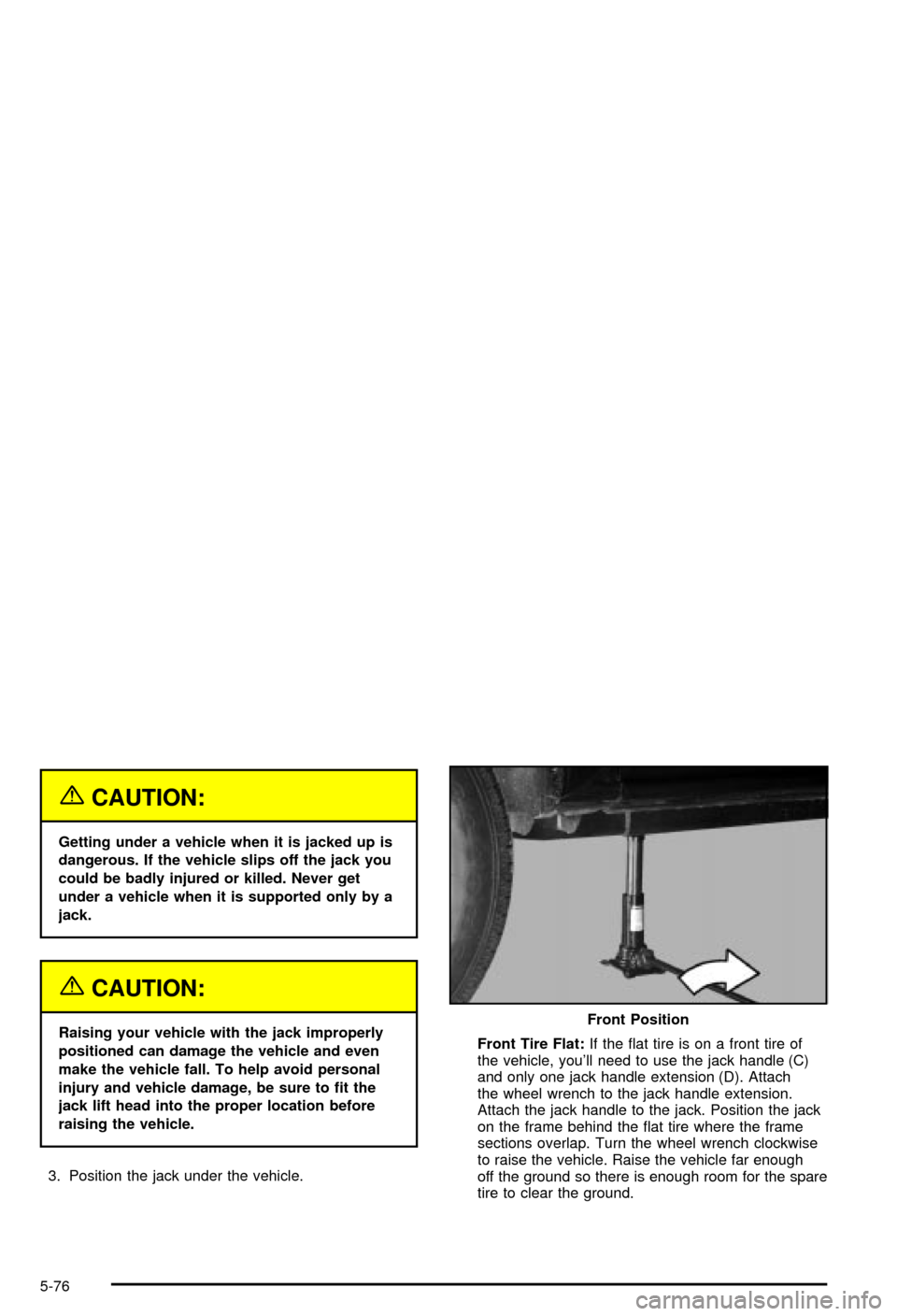
3. Position the jack under the vehicle.Front Tire Flat:If the ¯at tire is on a front tire of
the vehicle, you'll need to use the jack handle (C)
and only one jack handle extension (D). Attach
the wheel wrench to the jack handle extension.
Attach the jack handle to the jack. Position the jack
on the frame behind the ¯at tire where the frame
sections overlap. Turn the wheel wrench clockwise
to raise the vehicle. Raise the vehicle far enough
off the ground so there is enough room for the spare
tire to clear the ground.Front Position
5-76
Page 410 of 492
Rear Tire Flat:If the ¯at tire is on a rear tire of the
vehicle, you'll need to use the jack handle (C)
and both jack handle extensions (D). Attach the
wheel wrench to the jack handle extensions. Attach
the jack handle to the jack.On all 1500 Series
vehicles, use the jacking pad provided on the rear
axle. On 2500 series vehicles, use the axle between
the spring and shock bracket. Turn the wheel
wrench clockwise to raise the vehicle. Raise the
vehicle far enough off the ground so there is enough
room for the spare tire to clear the ground.
4. Remove all the wheel
nuts and take off the
¯at tire. Rear Position 1500
Series
Rear Position 2500
Series
5-77
Page 412 of 492
7. Turn the wheel wrench counterclockwise to lower
the vehicle. Lower the jack completely. Front Position
Rear Position 1500
SeriesRear Position 2500
Series
5-79
Page 413 of 492
8. Tighten the nuts ®rmly in a crisscross sequence as
shown by turning the wheel wrench clockwise.
{CAUTION:
Incorrect wheel nuts or improperly tightened
wheel nuts can cause the wheel to come loose
and even come off. This could lead to an
accident. Be sure to use the correct wheel
nuts. If you have to replace them, be sure to
get new GM original equipment wheel nuts.
Stop somewhere as soon as you can and have
the nuts tightened with a torque wrench to the
proper torque speci®cation. See ªCapacities
and Speci®cationsº in the Index for wheel nut
torque speci®cation.
Notice:Improperly tightened wheel nuts can lead
to brake pulsation and rotor damage. To avoid
expensive brake repairs, evenly tighten the wheel
nuts in the proper sequence and to the proper
torque speci®cation. See ªCapacities and
Speci®cationsº in the index for the wheel nut torque
speci®cation.
5-80
Page 415 of 492
A. Spare Tire (Valve Stem Pointed Down)
B. Hoist Assembly
C. Hoist Cable
D. Tire Retainer
E. Hoist Shaft
F. Hoist End of Extension Tool
G. Hoist Shaft Access Hole
H. Wheel Wrench
I. Jack Handle Extensions
J. Hoist Lock (If Equipped))1. Put the tire on the
ground at the rear of
the vehicle with
the valve stem pointed
down and toward
the rear of the vehicle.
2. Tilt the retainer (D) downward and through the
wheel opening. Make sure the retainer is fully
seated across the underside of the wheel.
5-82