Page 25 of 120

INSTRUMENT AND CONTROL FUNCTIONS
3-10
3 To set the engine speed indicator light
deactivation functionNOTE:_ �
The indicator light deactivation
function can be set between 7,000
and 12,000 r/min in increments of
500 r/min.
�
Be sure to set the deactivation
function to a higher engine speed
than for the activation function,
otherwise the engine speed indi-
cator light will remain deactivated.
_1. Push the “RESET” button to select
the desired engine speed for de-
activating the indicator light.
2. Push the “SELECT” button to con-
firm the selected engine speed.
The control mode changes to the
engine speed indicator light bright-
ness function.To adjust the engine speed indicator
light brightness1. Push the “RESET” button to select
the desired indicator light bright-
ness level.
2. Push the “SELECT” button to con-
firm the selected indicator light
brightness level. The multi-func-
tion display will return to the odom-
eter, tripmeter or clock mode.
U5PWE0.book Page 10 Friday, December 7, 2001 5:14 PM
Page 26 of 120
INSTRUMENT AND CONTROL FUNCTIONS
3-11
3
EAU00101
Tachometer The electric tachometer allows the rider
to monitor the engine speed and keep it
within the ideal power range.
EC000003
CAUTION:_ Do not operate the engine in the ta-
chometer red zone.
Red zone: 11,750 r/min and above _
EAU00109
Anti-theft alarm (optional) This motorcycle can be equipped with
an optional anti-theft alarm by a
Yamaha dealer. Contact a Yamaha
dealer for more information.
EAU00118
Handlebar switches
EAU04553
Pass switch “PASS”
Press this switch to flash the head-
lights.
EAU03888
Dimmer switch “/”
Set this switch to “” for the high
beam and to “” for the low beam.
1. Tachometer
2. Tachometer red zone
1. Pass switch “PASS”
2. Dimmer switch “/”
3. Turn signal switch “/”
4. Horn switch “”
U5PWE0.book Page 11 Friday, December 7, 2001 5:14 PM
Page 27 of 120

INSTRUMENT AND CONTROL FUNCTIONS
3-12
3
EAU03889
Turn signal switch “/”
To signal a right-hand turn, push this
switch to “”. To signal a left-hand
turn, push this switch to “”. When
released, the switch returns to the cen-
ter position. To cancel the turn signal
lights, push the switch in after it has re-
turned to the center position.
EAU00129
Horn switch “”
Press this switch to sound the horn.
EAU03890
Engine stop switch “/”
Set this switch to “” before starting
the engine. Set this switch to “” to
stop the engine in case of an emergen-
cy, such as when the motorcycle over-
turns or when the throttle cable is
stuck.
EAU04557
Light switch “//”
Set this switch to “” to turn on the
auxiliary lights, meter lighting, taillight
and license plate light. Set the switch to
“” to turn on the headlights also. Set
the switch to “” to turn off all the
lights.
EAU00143
Start switch “”
Push this switch to crank the engine
with the starter.
EC000005
CAUTION:_ See page 5-1 for starting instruc-
tions prior to starting the engine. _
1. Engine stop switch “/”
2. Light switch “//”
3. Start switch “”
U5PWE0.book Page 12 Friday, December 7, 2001 5:14 PM
Page 28 of 120

INSTRUMENT AND CONTROL FUNCTIONS
3-13
3
EAU00152
Clutch lever The clutch lever is located at the left
handlebar grip. To disengage the
clutch, pull the lever toward the handle-
bar grip. To engage the clutch, release
the lever. The lever should be pulled
rapidly and released slowly for smooth
clutch operation.
The clutch lever is equipped with a
clutch switch, which is part of the ignition
circuit cut-off system. (See page 3-26
for an explanation of the ignition circuit
cut-off system.)
EAU00157
Shift pedal The shift pedal is located on the left
side of the engine and is used in com-
bination with the clutch lever when
shifting the gears of the 6-speed con-
stant-mesh transmission equipped on
this motorcycle.
EAU00161
Brake lever The brake lever is located at the right
handlebar grip. To apply the front brake,
pull the lever toward the handlebar grip.
The brake lever is equipped with a posi-
tion adjusting dial. To adjust the dis-
tance between the brake lever and the
handlebar grip, turn the adjusting dial
while holding the lever pushed away
from the handlebar grip. Make sure that
the appropriate setting on the adjusting
dial is aligned with the arrow mark on
the brake lever.
1. Clutch lever
1. Shift pedal
1. Brake lever
2. Brake lever position adjusting dial
3. Arrow mark
a. Distance between brake lever and handlebar
grip
U5PWE0.book Page 13 Friday, December 7, 2001 5:14 PM
Page 29 of 120
INSTRUMENT AND CONTROL FUNCTIONS
3-14
3
EAU00162
Brake pedal The brake pedal is on the right side of
the motorcycle. To apply the rear
brake, press down on the brake pedal.
EAU04068
Fuel tank cap To open the fuel tank cap
Open the fuel tank cap lock cover, in-
sert the key into the lock, and then turn
it 1/4 turn clockwise. The lock will be re-
leased and the fuel tank cap can be
opened.
To close the fuel tank cap
1. Push the fuel tank cap into posi-
tion with the key inserted in the
lock.
2. Remove the key, and then close
the lock cover.
NOTE:_ The fuel tank cap cannot be closed un-
less the key is in the lock. In addition,
the key cannot be removed if the cap is
not properly closed and locked. _
EWA00025
WARNING
_ Make sure that the fuel tank cap is
properly closed before riding. _
1. Brake pedal
1. Fuel tank cap lock cover
2. Unlock.
U5PWE0.book Page 14 Friday, December 7, 2001 5:14 PM
Page 30 of 120

INSTRUMENT AND CONTROL FUNCTIONS
3-15
3
EAU03753
Fuel Make sure that there is sufficient fuel in
the tank. Fill the fuel tank to the bottom
of the filler tube as shown.
EW000130
WARNING
_ �
Do not overfill the fuel tank, oth-
erwise it may overflow when the
fuel warms up and expands.
�
Avoid spilling fuel on the hot
engine.
_
EAU00185
CAUTION:_ Immediately wipe off spilled fuel
with a clean, dry, soft cloth, since
fuel may deteriorate painted surfac-
es or plastic parts. _
EAU04518
ECA00104
CAUTION:_ Use only unleaded gasoline. The
use of leaded gasoline will cause se-
vere damage to internal engine
parts, such as the valves and piston
rings, as well as to the exhaust sys-
tem. _
Your Yamaha engine has been de-
signed to use regular unleaded gaso-
line with a research octane number of
95 or higher. If knocking (or pinging)
occurs, use a gasoline of a different
brand or premium unleaded fuel. Use
of unleaded fuel will extend spark plug
life and reduce maintenance costs.
1. Fuel tank filler tube
2. Fuel level
Recommended fuel:
PREMIUM UNLEADED
GASOLINE ONLY
Fuel tank capacity:
Total amount:
17 L
Amount remaining when the fuel
level warning light comes on:
3.3 L
U5PWE0.book Page 15 Friday, December 7, 2001 5:14 PM
Page 31 of 120

INSTRUMENT AND CONTROL FUNCTIONS
3-16
3
EAU02955
Fuel tank breather hose Before operating the motorcycle:�
Check the fuel tank breather hose
connection.
�
Check the fuel tank breather hose
for cracks or damage, and replace
it if damaged.
�
Make sure that the end of the fuel
tank breather hose is not blocked,
and clean it if necessary.
EAU03098*
Catalytic converter This motorcycle is equipped with a cat-
alytic converter in the muffler.
EW000128
WARNING
_ The exhaust system is hot after op-
eration. Make sure that the exhaust
system has cooled down before do-
ing any maintenance work. _
EC000114
CAUTION:_ The following precautions must be
observed to prevent a fire hazard or
other damages.�
Use only unleaded gasoline.
The use of leaded gasoline will
cause unrepairable damage to
the catalytic converter.
�
Never park the motorcycle near
possible fire hazards such as
grass or other materials that
easily burn.
�
Do not allow the engine to idle
too long.
_
1. Fuel tank breather hose
U5PWE0.book Page 16 Friday, December 7, 2001 5:14 PM
Page 32 of 120
INSTRUMENT AND CONTROL FUNCTIONS
3-17
3
EAU04493
Seats Rider seat
To remove the rider seatPull up the rear corners of the rider seat
as shown, remove the bolts, and then
pull the seat off.To install the rider seat
Insert the projection on the front of the
rider seat into the seat holder as
shown, place the seat in the original
position, and then install the bolts.Passenger seat
To remove the passenger seat
1. Insert the key into the seat lock,
and then turn it counterclockwise.
2. While holding the key in that posi-
tion, lift the front of the passenger
seat and pull it forward.
1. Bolt (× 2)
1. Projection
2. Seat holder
1. Passenger seat lock
2. Unlock.
U5PWE0.book Page 17 Friday, December 7, 2001 5:14 PM
 1
1 2
2 3
3 4
4 5
5 6
6 7
7 8
8 9
9 10
10 11
11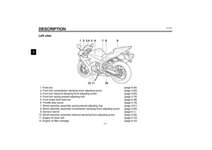 12
12 13
13 14
14 15
15 16
16 17
17 18
18 19
19 20
20 21
21 22
22 23
23 24
24 25
25 26
26 27
27 28
28 29
29 30
30 31
31 32
32 33
33 34
34 35
35 36
36 37
37 38
38 39
39 40
40 41
41 42
42 43
43 44
44 45
45 46
46 47
47 48
48 49
49 50
50 51
51 52
52 53
53 54
54 55
55 56
56 57
57 58
58 59
59 60
60 61
61 62
62 63
63 64
64 65
65 66
66 67
67 68
68 69
69 70
70 71
71 72
72 73
73 74
74 75
75 76
76 77
77 78
78 79
79 80
80 81
81 82
82 83
83 84
84 85
85 86
86 87
87 88
88 89
89 90
90 91
91 92
92 93
93 94
94 95
95 96
96 97
97 98
98 99
99 100
100 101
101 102
102 103
103 104
104 105
105 106
106 107
107 108
108 109
109 110
110 111
111 112
112 113
113 114
114 115
115 116
116 117
117 118
118 119
119

