Page 81 of 108

PERIODIC MAINTENANCE AND MINOR REPAIR
6-34
6 4. Install the lens by installing the
screws.
EC000108
CAUTION:@ Do not overtighten the screws, oth-
erwise the lens may break. @
EAU01579
Supporting the motorcycle Since this model is not equipped with a
centerstand, follow these precautions
when removing the front and rear
wheel or performing other maintenance
requiring the motorcycle to stand up-
right. Check that the motorcycle is in a
stable and level position before starting
any maintenance. A strong wooden
box can be placed under the engine for
added stability.
To service the front wheel
1. Stabilize the rear of the motorcycle
by using a motorcycle stand or, if
an additional motorcycle stand is
not available, by placing a jack un-
der the frame in front of the rear
wheel.
2. Raise the front wheel off the
ground by using a motorcycle
stand.To service the rear wheel
Raise the rear wheel off the ground by
using a motorcycle stand or, if a motor-
cycle stand is not available, by placing
a jack either under each side of the
frame in front of the rear wheel or under
each side of the swingarm.
1. Screw (× 3)XVS650A
U5SCE0.book Page 34 Thursday, June 7, 2001 11:24 AM
Page 82 of 108

PERIODIC MAINTENANCE AND MINOR REPAIR
6-35
6
EAU03737
Front wheel To remove the front wheel
EW000122
WARNING
_ �
It is advisable to have a Yamaha
dealer service the wheel.
�
Securely support the motor-
cycle so that there is no danger
of it falling over.
_1. Disconnect the speedometer ca-
ble from the front wheel.2. Loosen the front wheel axle pinch
bolt.
3. Remove the rubber cap, and then
loosen the wheel axle.
4. Lift the front wheel off the ground
according to the procedure on
page 6-34.
5. Pull the wheel axle out, and then
remove the wheel.
ECA00048
CAUTION:_ Do not apply the brake after the
wheel has been removed together
with the brake disc, otherwise the
brake pads will be forced shut. _
EAU03885
To install the front wheel
1. Install the speedometer gear unit
into the wheel hub so that the pro-
jections mesh with the slots.
2. Lift the wheel up between the fork
legs.NOTE:_ Make sure that there is enough space
between the brake pads before insert-
ing the brake disc and that the slot in
the speedometer gear unit fits over the
retainer on the fork leg. _3. Insert the wheel axle.
1. Speedometer cable
1. Rubber cap
2. Wheel axle
3. Front wheel axle pinch bolt
1. Speedometer gear unit
2. Speedometer cable
U5SCE0.book Page 35 Thursday, June 7, 2001 11:24 AM
Page 83 of 108

PERIODIC MAINTENANCE AND MINOR REPAIR
6-36
6 4. Lower the front wheel so that it is
on the ground.
5. Push down hard on the handlebar
several times to check for proper
fork operation.
6. Tighten the wheel axle to the
specified torque, and then install
the rubber cap.
7. Tighten the front wheel axle pinch
bolt to the specified torque.
8. Connect the speedometer cable.
EAU01350
Rear wheel To remove the rear wheel
EW000122
WARNING
@ �
It is advisable to have a Yamaha
dealer service the wheel.
�
Securely support the motorcycle
so that there is no danger of it
falling over.
@1. Loosen the axle nut.2. Disconnect the brake torque rod
from the brake shoe plate by re-
moving the bolt.
3. Loosen the brake torque rod bolt
at the swingarm.
4. Remove the brake pedal free play
adjusting nut, and then disconnect
the brake rod from the brake cam-
shaft lever.
5. Remove panel A. (See page 6-6
for panel removal and installation
procedures.) Tightening torque:
Wheel axle:
59 Nm (5.9 m·kgf)
Tightening torque:
Front wheel axle pinch bolt:
20 Nm (2.0 m·kgf)1. Axle nut
1. Brake pedal free play adjusting nut
2. Brake camshaft lever
3. Brake rod
4. Bolt (shoe plate)
5. Brake torque rod
6. Bolt (swingarm)
U5SCE0.book Page 36 Thursday, June 7, 2001 11:24 AM
Page 84 of 108

PERIODIC MAINTENANCE AND MINOR REPAIR
6-37
66. Remove the bolts that secure the
final gear case to the swingarm.
7. Lift the rear wheel off the ground
according to the procedure on
page 6-34.
8. While supporting the drive shaft,
pull the rear wheel back to remove
the following parts as an assem-
bly: wheel, wheel axle, final gear
case, and drive shaft.
NOTE:@ Make sure to support the drive shaft as
it is being pulled out. @
EAU04191
To install the rear wheel
1. Install the rear wheel, wheel axle,
final gear case, and drive shaft by
pushing the wheel forward and
guiding the drive shaft into the
middle gear universal joint.
2. Install the final gear case bolts,
and then tighten them to the spec-
ified torque.3. Install the brake rod onto the brake
camshaft lever, and then install
the brake pedal free play adjusting
nut onto the brake rod.
4. Install the brake torque rod bolt at
the brake shoe plate, and then
tighten both bolts to the specified
torque.
5. Install the panel.
6. Lower the rear wheel so that it is
on the ground.
7. Tighten the axle nut to the speci-
fied torque.
8. Adjust the brake pedal free play.
(See page 6-21 for brake pedal
free play adjustment procedures.)
1. Bolt (× 4)
2. Final gear case
1. Middle gear universal joint
2. Drive shaft
Tightening torque:
Final gear case bolt:
74 Nm (7.4 m·kgf)
Tightening torque:
Brake torque rod bolt:
20 Nm (2.0 m·kgf)
Tightening torque:
Axle nut:
92 Nm (9.2 m·kgf)
U5SCE0.book Page 37 Thursday, June 7, 2001 11:24 AM
Page 85 of 108
PERIODIC MAINTENANCE AND MINOR REPAIR
6-38
6
EW000103
WARNING
_ After adjusting the brake pedal free
play, check the operation of the
brake light. _
EAU01008
Troubleshooting Although Yamaha motorcycles receive
a thorough inspection before shipment
from the factory, trouble may occur dur-
ing operation. Any problem in the fuel,
compression, or ignition systems, for
example, can cause poor starting and
loss of power.
The following troubleshooting chart
represents a quick and easy procedure
for checking these vital systems your-
self. However, should your motorcycle
require any repair, take it to a Yamaha
dealer, whose skilled technicians have
the necessary tools, experience, and
know-how to service the motorcycle
properly.
Use only genuine Yamaha replace-
ment parts. Imitation parts may look
like Yamaha parts, but they are often
inferior, have a shorter service life and
can lead to expensive repair bills.
U5SCE0.book Page 38 Thursday, June 7, 2001 11:24 AM
Page 86 of 108

PERIODIC MAINTENANCE AND MINOR REPAIR
6-39
6
EAU01297
Troubleshooting chart
EW000125
WARNING
@ Keep away open flames and do not smoke while checking or working on the fuel system.@
Check the fuel level in
the fuel tank.1. Fuel
There is enough fuel.
There is no fuel.
Check the compression.
Supply fuel.
The engine does not start.
Check the compression.
Operate the electric starter.2. Compression
There is compression.
There is no compression.
Check the ignition.
Have a Yamaha dealer
check the vehicle.
Remove the spark plugs
and check the electrodes.3. Ignition
Wipe off with a dry cloth and correct the
spark plug gaps, or replace the spark plugs.
Have a Yamaha dealer check the vehicle.
The engine does not start.
Have a Yamaha dealer
check the vehicle.
The engine does not start.
Check the battery.
Operate the electric starter.4. Battery
The engine turns over
quickly.
The engine turns over
slowly.
The battery is good.Check the battery lead connections,
and charge the battery if necessary.
DryWet
Open the throttle halfway and operate
the electric starter.
U5SCE0.book Page 39 Thursday, June 7, 2001 11:24 AM
Page 87 of 108
MOTORCYCLE CARE AND STORAGE
7
Care .................................................................................................. 7-1
Storage .............................................................................................. 7-4
U5SCE0.book Page 1 Thursday, June 7, 2001 11:24 AM
Page 88 of 108

7-1
7
EAU03412
7-MOTORCYCLE CARE AND STORAGECare While the open design of a motorcycle
reveals the attractiveness of the tech-
nology, it also makes it more vulnera-
ble. Rust and corrosion can develop
even if high-quality components are
used. A rusty exhaust pipe may go un-
noticed on a car, however, it detracts
from the overall appearance of a
motorcycle. Frequent and proper care
does not only comply with the terms of
the warranty, but it will also keep your
motorcycle looking good, extend its life
and optimize its performance.Before cleaning
1. Cover the muffler outlets with plas-
tic bags after the engine has
cooled down.
2. Make sure that all caps and covers
as well as all electrical couplers
and connectors, including the
spark plug caps, are tightly in-
stalled.
3. Remove extremely stubborn dirt,
like oil burnt onto the crankcase,
with a degreasing agent and a
brush, but never apply such prod-
ucts onto seals, gaskets and
wheel axles. Always rinse the dirt
and degreaser off with water.Cleaning
ECA00010
CAUTION:@ �
Avoid using strong acidic wheel
cleaners, especially on spoked
wheels. If such products are
used on hard-to-remove dirt, do
not leave the cleaner on the af-
fected area any longer than in-
structed. Also, thoroughly rinse
the area off with water, immedi-
ately dry it, and then apply a
corrosion protection spray.
�
Improper cleaning can damage
windshields, cowlings, panels
and other plastic parts. Use
only a soft, clean cloth or
sponge with mild detergent and
water to clean plastic.
U5SCE0.book Page 1 Thursday, June 7, 2001 11:24 AM
 1
1 2
2 3
3 4
4 5
5 6
6 7
7 8
8 9
9 10
10 11
11 12
12 13
13 14
14 15
15 16
16 17
17 18
18 19
19 20
20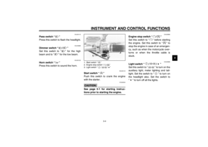 21
21 22
22 23
23 24
24 25
25 26
26 27
27 28
28 29
29 30
30 31
31 32
32 33
33 34
34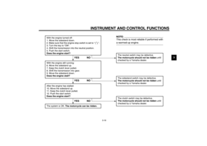 35
35 36
36 37
37 38
38 39
39 40
40 41
41 42
42 43
43 44
44 45
45 46
46 47
47 48
48 49
49 50
50 51
51 52
52 53
53 54
54 55
55 56
56 57
57 58
58 59
59 60
60 61
61 62
62 63
63 64
64 65
65 66
66 67
67 68
68 69
69 70
70 71
71 72
72 73
73 74
74 75
75 76
76 77
77 78
78 79
79 80
80 81
81 82
82 83
83 84
84 85
85 86
86 87
87 88
88 89
89 90
90 91
91 92
92 93
93 94
94 95
95 96
96 97
97 98
98 99
99 100
100 101
101 102
102 103
103 104
104 105
105 106
106 107
107
