Page 17 of 108

INSTRUMENT AND CONTROL FUNCTIONS
3
Main switch/steering lock .................................................................. 3-1
Indicator and warning lights ............................................................. 3-2
Speedometer unit .............................................................................. 3-3
Anti-theft alarm (optional) .................................................................. 3-3
Handlebar switches ........................................................................... 3-3
Clutch lever ....................................................................................... 3-5
Shift pedal (XVS650).......................................................................... 3-5
Shift pedal (XVS650A) ....................................................................... 3-5
Brake lever ........................................................................................ 3-6
Brake pedal ....................................................................................... 3-6
Fuel tank cap ..................................................................................... 3-7
Fuel ................................................................................................... 3-7
Fuel cock ........................................................................................... 3-9
Starter (choke) knob......................................................................... 3-10
Seats (XVS650) ............................................................................... 3-11
Seats (XVS650A) ............................................................................. 3-12
Helmet holder .................................................................................. 3-13
Storage compartment ..................................................................... 3-13
Adjusting the shock absorber assembly .......................................... 3-15
Luggage strap holders .................................................................... 3-16
Sidestand ........................................................................................ 3-17
Ignition circuit cut-off system ........................................................... 3-17
U5SCE0.book Page 1 Thursday, June 7, 2001 11:24 AM
Page 18 of 108

3-1
3
EAU00027
3-INSTRUMENT AND CONTROL FUNCTIONS
EAU00029
Main switch/steering lock The main switch/steering lock controls
the ignition and lighting systems, and is
used to lock the steering. The various
positions are described below.
EAU00036
ON
All electrical systems are supplied with
power, and the engine can be started.
The key cannot be removed.
EAU00038
OFF
All electrical systems are off. The key
can be removed.
EAU00040
LOCK
The steering is locked, and all electrical
systems are off. The key can be re-
moved.
To lock the steering1. Turn the handlebars all the way to
the left.
2. Push the key in from the “OFF” po-
sition, and then turn it to “LOCK”
while still pushing it.
3. Remove the key.
To unlock the steeringPush the key in, and then turn it to
“OFF” while still pushing it.
EW000016
WARNING
@ Never turn the key to “OFF” or
“LOCK” while the motorcycle is
moving, otherwise the electrical
systems will be switched off, which
may result in loss of control or an
accident. Make sure that the motor-
cycle is stopped before turning the
key to “OFF” or “LOCK”. @1. Push.
2. Turn.
U5SCE0.book Page 1 Thursday, June 7, 2001 11:24 AM
Page 19 of 108

The steering is locked, and the taillight
and auxiliary light are on, but all other
electrical systems are off. The key can
be removed.
The s")
INSTRUMENT AND CONTROL FUNCTIONS
3-2
3
EAU00048
(Parking)
The steering is locked, and the taillight
and auxiliary light are on, but all other
electrical systems are off. The key can
be removed.
The steering must be locked before the
key can be turned to “”.
ECA00043
CAUTION:_ Do not use the parking position for
an extended length of time, other-
wise the battery may discharge. _
EAU03034
Indicator and warning lights
EAU00063
High beam indicator light “”
This indicator light comes on when the
high beam of the headlight is switched
on.
EAU00057
Turn signal indicator light “”
This indicator light flashes when the
turn signal switch is pushed to the left
or right.
EAU00061
Neutral indicator light “”
This indicator light comes on when the
transmission is in the neutral position.
EAU04238
Engine trouble warning light “”
This warning light comes on or flashes
when an electrical circuit monitoring
the engine is defective. When this oc-
curs, have a Yamaha dealer check the
self-diagnosis system.NOTE:_ This warning light comes on for a few
seconds when the key is turned to
“ON”, but this does not indicate a mal-
function. _
1. High beam indicator light “”
2. Turn signal indicator light “”
3. Neutral indicator light “”
4. Engine trouble warning light “”
U5SCE0.book Page 2 Thursday, June 7, 2001 11:24 AM
Page 20 of 108

INSTRUMENT AND CONTROL FUNCTIONS
3-3
3
EAU00095
Speedometer unit The speedometer unit is equipped with
a speedometer, an odometer and a
tripmeter. The speedometer shows
riding speed. The odometer shows the
total distance traveled. The tripmeter
shows the distance traveled since it
was last set to zero with the reset knob.
The tripmeter can be used to estimate
the distance that can be traveled with a
full tank of fuel. This information will en-
able you to plan future fuel stops.
EAU00109
Anti-theft alarm (optional) This motorcycle can be equipped with
an optional anti-theft alarm by a
Yamaha dealer. Contact a Yamaha
dealer for more information.
EAU00118
Handlebar switches
EAU03889
Turn signal switch “/”
To signal a right-hand turn, push this
switch to “”. To signal a left-hand
turn, push this switch to “”. When
released, the switch returns to the cen-
ter position. To cancel the turn signal
lights, push the switch in after it has re-
turned to the center position.
1. Tripmeter reset knob
2. Speedometer
3. Odometer
4. Tripmeter
1. Turn signal switch “/”
2. Pass switch “”
3. Dimmer switch “/”
4. Horn switch “”
U5SCE0.book Page 3 Thursday, June 7, 2001 11:24 AM
Page 21 of 108

INSTRUMENT AND CONTROL FUNCTIONS
3-4
3
EAU00119
Pass switch “”
Press this switch to flash the headlight.
EAU03888
Dimmer switch “/”
Set this switch to “” for the high
beam and to “” for the low beam.
EAU00129
Horn switch “”
Press this switch to sound the horn.
EAU00143
Start switch “”
Push this switch to crank the engine
with the starter.
EC000005
CAUTION:@ See page 5-1 for starting instruc-
tions prior to starting the engine. @
EAU03890
Engine stop switch “/”
Set this switch to “” before starting
the engine. Set this switch to “” to
stop the engine in case of an emergen-
cy, such as when the motorcycle over-
turns or when the throttle cable is
stuck.
EAU03898
Light switch “//”
Set this switch to “” to turn on the
auxiliary light, meter lighting and tail-
light. Set the switch to “” to turn on
the headlight also. Set the switch to
“” to turn off all the lights.
1. Start switch “”
2. Engine stop switch “/”
3. Light switch “//”
U5SCE0.book Page 4 Thursday, June 7, 2001 11:24 AM
Page 22 of 108

INSTRUMENT AND CONTROL FUNCTIONS
3-5
3
EAU00152
Clutch lever The clutch lever is located at the left
handlebar grip. To disengage the
clutch, pull the lever toward the handle-
bar grip. To engage the clutch, release
the lever. The lever should be pulled
rapidly and released slowly for smooth
clutch operation.
The clutch lever is equipped with a
clutch switch, which is part of the igni-
tion circuit cut-off system. (See page
3-16 for an explanation of the ignition
circuit cut-off system.)
EAU00157
Shift pedal (XVS650)The shift pedal is located on the left
side of the engine and is used in com-
bination with the clutch lever when
shifting the gears of the 5-speed con-
stant-mesh transmission equipped on
this motorcycle.
EAU01215
Shift pedal (XVS650A)The shift pedal is located on the left
side of the engine and is used in com-
bination with the clutch lever when
shifting the gears of the 5-speed con-
stant-mesh transmission equipped on
this motorcycle.NOTE:_ Use your toes or heel to shift up and
your toes to shift down. _
1. Clutch lever
1. Shift pedalXVS650
1. Shift pedalXVS650A
U5SCE0.book Page 5 Thursday, June 7, 2001 11:24 AM
Page 23 of 108
INSTRUMENT AND CONTROL FUNCTIONS
3-6
3
EAU00158
Brake lever The brake lever is located at the right
handlebar grip. To apply the front
brake, pull the lever toward the handle-
bar grip.
EAU00162
Brake pedal The brake pedal is on the right side of
the motorcycle. To apply the rear
brake, press down on the brake pedal.
1. Brake lever
1. Brake pedalXVS650
1. Brake pedalXVS650A
U5SCE0.book Page 6 Thursday, June 7, 2001 11:24 AM
Page 24 of 108

INSTRUMENT AND CONTROL FUNCTIONS
3-7
3
EAU00169
Fuel tank cap To remove the fuel tank cap
Insert the key into the lock and turn it
1/4 turn clockwise. The lock will be re-
leased and the fuel tank cap can be
removed.
To install the fuel tank cap
1. Insert the fuel tank cap into the
tank opening with the key inserted
in the lock and with the “” mark
facing forward.
2. Turn the key counterclockwise to
the original position, and then re-
move it.
NOTE:@ The fuel tank cap cannot be installed
unless the key is in the lock. In addition,
the key cannot be removed if the cap is
not properly installed and locked. @
EW000024
WARNING
@ Make sure that the fuel tank cap is
properly installed before riding. @
EAU03753
Fuel Make sure that there is sufficient fuel in
the tank. Fill the fuel tank to the bottom
of the filler tube as shown.
EW000130
WARNING
_ �
Do not overfill the fuel tank, oth-
erwise it may overflow when the
fuel warms up and expands.
�
Avoid spilling fuel on the hot
engine.
_
1.“” mark
2. Unlock.
1. Fuel tank filler tube
2. Fuel level
U5SCE0.book Page 7 Thursday, June 7, 2001 11:24 AM
 1
1 2
2 3
3 4
4 5
5 6
6 7
7 8
8 9
9 10
10 11
11 12
12 13
13 14
14 15
15 16
16 17
17 18
18 19
19 20
20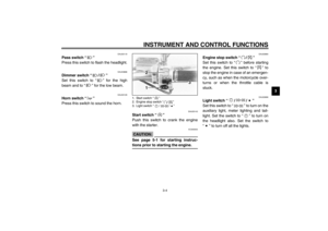 21
21 22
22 23
23 24
24 25
25 26
26 27
27 28
28 29
29 30
30 31
31 32
32 33
33 34
34 35
35 36
36 37
37 38
38 39
39 40
40 41
41 42
42 43
43 44
44 45
45 46
46 47
47 48
48 49
49 50
50 51
51 52
52 53
53 54
54 55
55 56
56 57
57 58
58 59
59 60
60 61
61 62
62 63
63 64
64 65
65 66
66 67
67 68
68 69
69 70
70 71
71 72
72 73
73 74
74 75
75 76
76 77
77 78
78 79
79 80
80 81
81 82
82 83
83 84
84 85
85 86
86 87
87 88
88 89
89 90
90 91
91 92
92 93
93 94
94 95
95 96
96 97
97 98
98 99
99 100
100 101
101 102
102 103
103 104
104 105
105 106
106 107
107