Page 17 of 100

3-3
EAU00102
TachometerTachometerThe tachometer allows the rider to
monitor the engine speed and keep it
within the ideal power range.
EC000003
cCDo not operate the engine in the
tachometer red zone.
Red zone: 7,000 r/min and above
EAU03888
Dimmer switch “%/&”Dimmer switchSet this switch to “&” for the high
beam and to “%” for the low beam.
EAU03889
Turn signal switch “4/6”Turn signal switchTo signal a right-hand turn, push this
switch to “6”. To signal a left-hand
turn, push this switch to “4”. When
released, the switch returns to the
center position. To cancel the turn
signal lights, push the switch in after
it has returned to the center position.
EAU00129
Horn switch “*”Horn switchPress this switch to sound the horn.
INSTRUMENT AND CONTROL FUNCTIONS
3
1
5&
N
a
1. Tachometer
a. Red zone
EAU00118
Handlebar switchesHandlebar switches
EAU03898
Light switch “9/
'
/:”
Light switchSet this switch to “
'
” to turn on the
auxiliary light, meter lighting and tail-
light. Set the switch to “:” to turn on
the headlight also. Set the switch to
“9” to turn off all the lights.
EAU00119
Pass switch “&”Pass switchPress this switch to flash the head-
light.
4 5 123*
1. Light switch “9/
'
/:”
2. Pass switch “&”
3. Dimmer switch “%/&”
4. Turn signal switch “4/6”
5. Horn switch “*”
4PT-E7 (English) 6/29/01 9:13 AM Page 16
Page 18 of 100

3-4
INSTRUMENT AND CONTROL FUNCTIONS
3
EAU03890
Engine stop switch “$/#”Engine stop switchSet this switch to “#” before starting
the engine. Set this switch to “$” to
stop the engine in case of an emer-
gency, such as when the motorcycle
overturns or when the throttle cable is
stuck.
EAU00143
Start switch “,”Start switchPush this switch to crank the engine
with the starter.
EC000005
cCSee page 5-1 for starting instruc-
tions prior to starting the engine.
1
2
,
1. Engine stop switch “$/#”
2. Start switch “,”
EAU00152
Clutch leverClutch leverThe clutch lever is located at the left
handlebar grip. To disengage the
clutch, pull the lever toward the han-
dlebar grip. To engage the clutch,
release the lever. The lever should
be pulled rapidly and released slowly
for smooth clutch operation.
The clutch lever is equipped with a
clutch switch, which is part of the igni-
tion circuit cut-off system. (See page
3-12 for an explanation of the ignition
circuit cut-off system.)
1
1. Clutch lever
4PT-E7 (English) 6/29/01 9:13 AM Page 17
Page 19 of 100
3-5
EAU00157
Shift pedalShift pedalThe shift pedal is located on the left
side of the engine and is used in
combination with the clutch lever
when shifting the gears of the
5-speed constant-mesh transmission
equipped on this motorcycle.INSTRUMENT AND CONTROL FUNCTIONS
3
1
1. Shift pedal
EAU00158
Brake leverBrake leverThe brake lever is located at the right
handlebar grip. To apply the front
brake, pull the lever toward the han-
dlebar grip.
1
1. Brake lever
EAU00162
Brake pedalBrake pedalThe brake pedal is on the right side
of the motorcycle. To apply the rear
brake, press down on the brake
pedal.
1
1. Brake pedal
4PT-E7 (English) 6/29/01 9:13 AM Page 18
Page 20 of 100

3-6
INSTRUMENT AND CONTROL FUNCTIONS
3
EAU00177
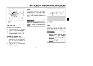
Fuel tank capFuel tank capTo remove the fuel tank cap
1. Insert the key into the lock and
turn it 1/4 turn counterclockwise.
2. Turn the fuel tank cap 1/3 turn
counterclockwise and pull it off.
To install the fuel tank cap
1. Insert the fuel tank cap into the
tank opening with the key insert-
ed in the lock, and then turn the
cap 1/3 turn clockwise.
2. Turn the key 1/4 turn clockwise,
and then remove it.
NOTE:
The fuel tank cap cannot be installed
unless the key is in the lock. In addi-
tion, the key cannot be removed if the
cap is not properly installed and
locked.
EW000023
wMake sure that the fuel tank cap is
properly closed and locked before
riding.
b
a
a. Unlock.
b. Open.
EAU03753
FuelFuelMake sure that there is sufficient fuel
in the tank. Fill the fuel tank to the
bottom of the filler tube as shown.
EW000130
w8Do not overfill the fuel tank,
otherwise it may overflow
when the fuel warms up and
expands.
8Avoid spilling fuel on the hot
engine.
2
1
1. Filler tube
2. Fuel level
4PT-E7 (English) 6/29/01 9:13 AM Page 19
Page 21 of 100
3-7
EAU00185
cCImmediately wipe off spilled fuel
with a clean, dry, soft cloth, since
fuel may deteriorate painted sur-
faces or plastic parts.
EAU04284
ECA00102
cCUse only unleaded gasoline. The
use of leaded gasoline will cause
severe damage to internal engine
parts, such as the valves and pis-
ton rings, as well as to the exhaust
system.
Your Yamaha engine has been
designed to use regular unleaded
gasoline with a research octane num-
ber of 91 or higher. If knocking (or
pinging) occurs, use a gasoline of a
different brand or premium unleaded
fuel. Use of unleaded fuel will extend
spark plug life and reduce mainte-
nance costs.
INSTRUMENT AND CONTROL FUNCTIONS
3Recommended fuel:
REGULAR UNLEADED
GASOLINE ONLY
Fuel tank capacity:
Total amount:
15.0 L
Reserve amount:
2.0 L 4PT-E7 (English) 6/29/01 9:13 AM Page 20
Page 22 of 100
3-8
INSTRUMENT AND CONTROL FUNCTIONS
3
EAU03050
Fuel cockFuel cockThe fuel cock supplies fuel from the
tank to the carburetor while filtering it
also.
The fuel cock has three positions:
OFF
With the lever in this position, fuel will
not flow. Always return the lever to
this position when the engine is not
running.
RES
ONFUEL
OFF
1
1. Arrow mark pointing over “OFF”
RES
This indicates reserve. If you run out
of fuel while riding, move the lever to
this position. Fill the tank at the first
opportunity. Be sure to set the lever
back to “ON” after refueling!
OFF
ONFUEL RES
1
RES
1. Arrow mark pointing over “RES”
ON
With the lever in this position, fuel
flows to the carburetor. Normal riding
is done with the lever in this position.
ON
FUEL
RES
OFF
1
ON
1. Arrow mark pointing over “ON”
RES: reserve position
ON: normal position
OFF: closed position
4PT-E7 (English) 6/29/01 9:13 AM Page 21
Page 23 of 100
3-9
EAU04038
Starter (choke) knob“1”Starter (choke) knobStarting a cold engine requires a rich-
er air-fuel mixture, which is supplied
by the starter (choke).
Move the knob in direction ato turn
on the starter (choke).
Move the knob in direction bto turn
off the starter (choke).INSTRUMENT AND CONTROL FUNCTIONS
3
1
b
a
1. Starter (choke) knob “1”
To install the seat
1. Insert the projections on the front
of the seat into the seat holders
as shown.
2. Place the seat in the original
position, and then tighten the
bolts.NOTE:
Make sure that the seat is properly
secured before riding.
1
2
1. Projection (
×2)
2. Seat holder (×2)
EAU00240
SeatSeatTo remove the seat
Remove the bolts, and then pull the
seat off.
1
1. Bolt (×2)
4PT-E7 (English) 6/29/01 9:13 AM Page 22
Page 24 of 100

3-10
INSTRUMENT AND CONTROL FUNCTIONS
3
EAU00260
Helmet holderHelmet holderTo open the helmet holder, insert the
key into the lock, and then turn the
key as shown.
To lock the helmet holder, place it in
the original position, and then remove
the key.
EW000030
wNever ride with a helmet attached
to the helmet holder, since the hel-
met may hit objects, causing loss
of control and possibly an acci-
dent.
1
a
1. Helmet holder
a. Open.
EAU03591
Adjusting the shock
absorber assemblyShock absorber assembly, adjustingThis shock absorber assembly is
equipped with a spring preload
adjusting nut.
EC000015
cCNever attempt to turn an adjusting
mechanism beyond the maximum
or minimum settings.Adjust the spring preload as follows.
1. Loosen the locknut.
a
b
1 2
1. Locknut
2. Adjusting nut
2. To increase the spring preload
and thereby harden the suspen-
sion, turn the adjusting nut in
direction a. To decrease the
spring preload and thereby soft-
en the suspension, turn the
adjusting nut in direction b.NOTE:
The spring preload setting is deter-
mined by measuring distance A,
shown in the illustration. The shorter
distance A is, the lower the spring
preload; the longer distance A is, the
higher the spring preload.
A
4PT-E7 (English) 6/29/01 9:13 AM Page 23


 knob“1”Starter (choke) knobStarting a cold engine requires a rich-
er air-fuel mixture, which is supplied
by the starter (choke).
Move the knob in direction ato turn
o")