Page 65 of 88
6-34
PERIODIC MAINTENANCE AND MINOR REPAIR
6
EC000103
cCDo not use a fuse of a higher
amperage rating than recommend-
ed to avoid causing extensive
damage to the electrical system
and possibly a fire.3. Turn the key to “ON” and turn on
the electrical circuits to check if
the devices operate.
4. If the fuse immediately blows
again, have a Yamaha dealer
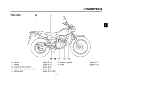
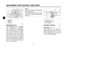
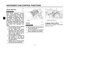
check the electrical system.2. Disconnect the headlight cou-
pler, and then remove the bulb
cover.
1
2
1. Headlight coupler
2. Bulb cover
EAU04189
Replacing the headlight bulbThis motorcycle is equipped with a
quartz bulb headlight. If the headlight
bulb burns out, replace it as follows.
1. Remove the headlight unit by
removing the screws.11. Screw (×2)
5RS-9-E0 (TW125) 7/30/01 6:03 PM Page 64
Page 66 of 88
6-35
PERIODIC MAINTENANCE AND MINOR REPAIR
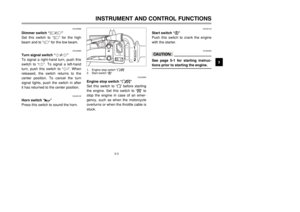
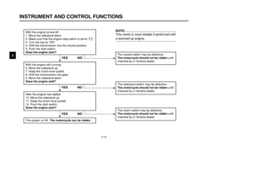
6 3. Unhook the headlight bulb hold-
er, and then remove the defec-
tive bulb.
EW000119
wHeadlight bulbs get very hot.
Therefore, keep flammable prod-
ucts away from a lit headlight bulb,
and do not touch the bulb until it
has cooled down.4. Place a new headlight bulb into
position, and then secure it with
the bulb holder.
1
1. Headlight bulb holder
5. Install the headlight bulb cover,
and then connect the coupler.
6. Install the headlight unit by
installing the screws.
7. Have a Yamaha dealer adjust
the headlight beam if necessary.
EC000105
cCDo not touch the glass part of the
headlight bulb to keep it free from
oil, otherwise the transparency of
the glass, the luminosity of the
bulb, and the bulb life will be
adversely affected. Thoroughly
clean off any dirt and fingerprints
on the headlight bulb using a cloth
moistened with alcohol or thinner.
a
a. Do not touch this area.
5RS-9-E0 (TW125) 7/30/01 6:03 PM Page 65
Page 67 of 88
6-36
PERIODIC MAINTENANCE AND MINOR REPAIR
6
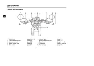
EAU03497
Replacing a turn signal light
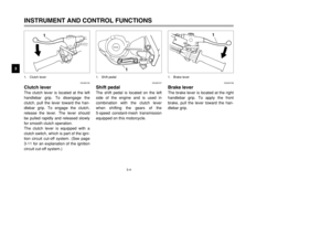
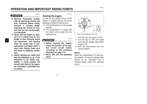
bulb1. Remove the turn signal light lens
by removing the screw.
2. Remove the defective bulb by
pushing it in and turning it coun-
terclockwise.
3. Insert a new bulb into the socket,
push it in, and then turn it clock-
wise until it stops.
4. Install the lens by installing the
screw.
1
2
3
1. Screw
2. Lens
3. bulb
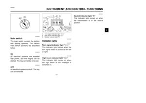
EAU01623
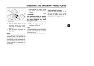
Replacing the tail/brake light
bulb1. Remove the tail/brake light lens
by removing the screws.
1
1. Screw (×2)
ECA00065
cCDo not overtighten the screw, oth-
erwise the lens may break.
5RS-9-E0 (TW125) 7/30/01 6:03 PM Page 66
Page 68 of 88

6-37
PERIODIC MAINTENANCE AND MINOR REPAIR
6 2. Remove the defective bulb by
pushing it in and turning it coun-
terclockwise.
3. Insert a new bulb into the socket,
push it in, and then turn it clock-
wise until it stops.
4. Install the lens by installing the
screws.
EC000108
cCDo not overtighten the screws,
otherwise the lens may break.
1
1. Bulb
To service the rear wheel
Raise the rear wheel off the ground
by using a motorcycle stand or, if a
motorcycle stand is not available, by
placing a jack either under each side
of the frame in front of the rear wheel
or under each side of the swingarm.
EAU01579
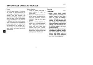
Supporting the motorcycleSince this model is not equipped with
a centerstand, follow these precau-
tions when removing the front and
rear wheel or performing other main-
tenance requiring the motorcycle to
stand upright. Check that the motor-
cycle is in a stable and level position
before starting any maintenance. A
strong wooden box can be placed
under the engine for added stability.
To service the front wheel
1. Stabilize the rear of the motorcy-
cle by using a motorcycle stand
or, if an additional motorcycle
stand is not available, by placing
a jack under the frame in front of
the rear wheel.
2. Raise the front wheel off the
ground by using a motorcycle
stand.
5RS-9-E0 (TW125) 7/30/01 6:03 PM Page 67
Page 69 of 88
6-38
PERIODIC MAINTENANCE AND MINOR REPAIR
6
EAU04387
Front wheelWheel (front)To remove the front wheelRemoving
EW000122
w8It is advisable to have a
Yamaha dealer service the
wheel.
8Securely support the motorcy-
cle so that there is no danger
of it falling over.
1
1. Rubber cover
2. Pull outward on the rubber cover
at the bottom of the left-side fork
leg, and then pull it off.
1
1. Rubber cover
1. Pull outward on the rubber cover
at the bottom of the right-side
fork leg, and then slide it up
along the fork leg.
5RS-9-E0 (TW125) 7/30/01 6:03 PM Page 68
Page 70 of 88
6-39
PERIODIC MAINTENANCE AND MINOR REPAIR
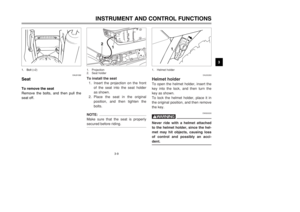
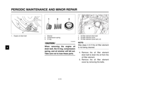
6 3. Disconnect the speedometer
cable from the front wheel.
4. Loosen the axle nut.
5. Lift the front wheel off the ground
according to the procedure on
page 6-37.
6. Remove the axle nut, pull the
wheel axle out, and then remove
the wheel.
ECA00048
cCDo not apply the brake after the
wheel has been removed together
with the brake disc, otherwise the
brake pads will be forced shut.
1
2
1. Speedometer cable
2. Axle nut
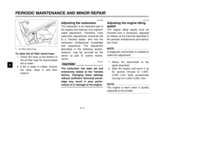
EAU04388
To install the front wheelInstalling1. Install the speedometer gear unit
into the wheel hub so that the
projections mesh with the slots.
2. Lift the wheel up between the
fork legs.
1
1. Speedometer gear unit
5RS-9-E0 (TW125) 7/30/01 6:03 PM Page 69
Page 71 of 88

6-40
PERIODIC MAINTENANCE AND MINOR REPAIR
6
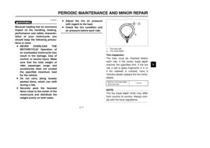
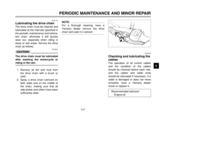
NOTE:
Make sure that there is enough
space between the brake pads
before inserting the brake disc and
that the slot in the speedometer gear
unit fits over the retainer on the fork
leg.3. Insert the wheel axle, and then
install the axle nut.
4. Lower the front wheel so that it is
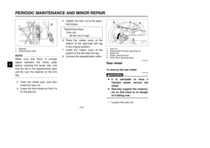
on the ground.5. Tighten the axle nut to the speci-
fied torque.
6. Place the rubber cover at the
bottom of the right-side fork leg
in the original position.
7. Install the rubber cover at the
bottom of the left-side fork leg.
8. Connect the speedometer cable.
2 1
1. Retainer
2. Speedometer cable
Tightening torque:
Axle nut:
90 Nm (9.0 m·kgf)
EAU03519
Rear wheelTo remove the rear wheel
EW000122
w8It is advisable to have a
Yamaha dealer service the
wheel.
8Securely support the motorcy-
cle so that there is no danger
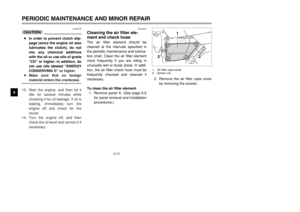
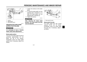
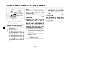
of it falling over.1. Loosen the axle nut.
5
a2
1
3
4
1. Axle nut
2. Brake pedal free play adjusting nut
3. Brake rod
4. Brake camshaft lever
5. Drive chain adjusting plate
5RS-9-E0 (TW125) 7/30/01 6:03 PM Page 70
Page 72 of 88

6-41
PERIODIC MAINTENANCE AND MINOR REPAIR
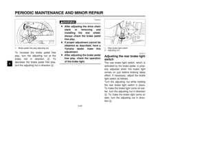
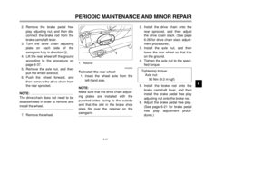
6 2. Remove the brake pedal free
play adjusting nut, and then dis-
connect the brake rod from the
brake camshaft lever.
3. Turn the drive chain adjusting
plate on each side of the
swingarm fully in direction a.
4. Lift the rear wheel off the ground
according to the procedure on
page 6-37.
5. Remove the axle nut, and then
pull the wheel axle out.
6. Push the wheel forward, and
then remove the drive chain from
the rear sprocket.
NOTE:
The drive chain does not need to be
disassembled in order to remove and
install the wheel.7. Remove the wheel.
EAU03520
To install the rear wheel
1. Insert the wheel axle from the
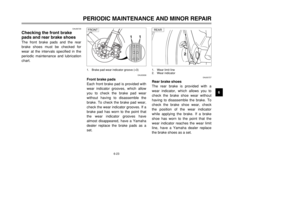
left-hand side.NOTE:
Make sure that the drive chain adjust-
ing plates are installed with the
punched sides facing to the outside
and that the slot in the brake shoe
plate fits over the retainer on the
swingarm.
1
1. Retainer
2. Install the drive chain onto the
rear sprocket, and then adjust
the drive chain slack. (See page
6-26 for drive chain slack adjust-
ment procedures.)
3. Install the axle nut, and then
lower the rear wheel so that it is
on the ground.
4. Tighten the axle nut to the speci-
fied torque.
5. Install the brake rod onto the
brake camshaft lever, and then
install the brake pedal free play
adjusting nut onto the brake rod.
6. Adjust the brake pedal free play.
(See page 6-21 for brake pedal
free play adjustment proce-
dures.) Tightening torque:
Axle nut:
90 Nm (9.0 m·kgf)
5RS-9-E0 (TW125) 7/30/01 6:03 PM Page 71


To remove the front wheelRemoving
EW000122
w8It is advisable to have a
Yamaha dealer service the
wheel.
8Securely support")
