Page 17 of 88

3-6
INSTRUMENT AND CONTROL FUNCTIONS
3
EAU03753
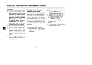
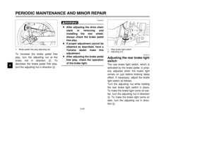
FuelMake sure that there is sufficient fuel
in the tank. Fill the fuel tank to the
bottom of the filler tube as shown.
EW000130
w8Do not overfill the fuel tank,
otherwise it may overflow
when the fuel warms up and
expands.
8Avoid spilling fuel on the hot
engine.
1
2
1. Filler tube
2. Fuel level
ECA00104
cCUse only unleaded gasoline. The
use of leaded gasoline will cause
severe damage to internal engine
parts, such as the valves and pis-
ton rings, as well as to the exhaust
system.Your Yamaha engine has been
designed to use regular unleaded
gasoline with a research octane num-
ber of 91 or higher. If knocking (or
pinging) occurs, use a gasoline of a
different brand or premium unleaded
fuel. Use of unleaded fuel will extend
spark plug life and reduce mainte-
nance costs.
EAU00185
cCImmediately wipe off spilled fuel
with a clean, dry, soft cloth, since
fuel may deteriorate painted sur-
faces or plastic parts.
EAU04284
Recommended fuel:
REGULAR UNLEADED
GASOLINE ONLY
Fuel tank capacity:
Total amount:
7.0 L
Reserve amount:
1.0 L
5RS-9-E0 (TW125) 7/30/01 6:03 PM Page 16
Page 18 of 88
3-7
INSTRUMENT AND CONTROL FUNCTIONS
3
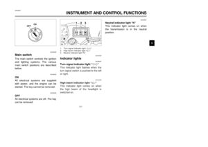
EAU03050
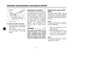
Fuel cockThe fuel cock supplies fuel from the
tank to the carburetor while filtering it
also.
The fuel cock has three positions:
OFF
With the lever in this position, fuel will
not flow. Always return the lever to
this position when the engine is not
running.
RES
ONFUEL
OFF
1
1. Arrow mark positioned over “OFF”
RES
This indicates reserve. If you run out
of fuel while riding, move the lever to
this position. Fill the tank at the first
opportunity. Be sure to set the lever
back to “ON” after refueling!
OFF
ONFUEL RES
1
RES
1. Arrow mark positioned over “RES”
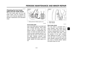
ON
With the lever in this position, fuel
flows to the carburetor. Normal riding
is done with the lever in this position.
ON
FUEL
RES
OFF
1
ON
1. Arrow mark positioned over “ON”
OFF: Closed position
ON: Normal position
RES: Reserve position
5RS-9-E0 (TW125) 7/30/01 6:03 PM Page 17
Page 19 of 88
 knob“1”Starting a cold engine requires a rich-
er air-fuel mixture, which is supplied
by the starter (choke).
Move the knob in direc")
3-8
INSTRUMENT AND CONTROL FUNCTIONS
3
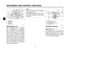
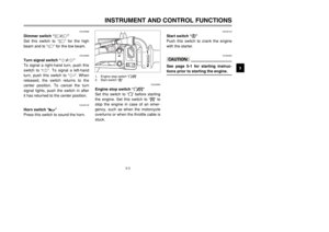
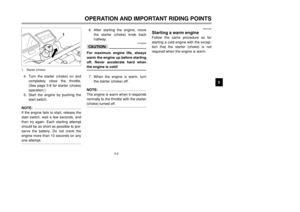
EAU04038
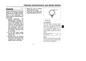
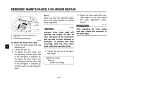
Starter (choke) knob“1”Starting a cold engine requires a rich-
er air-fuel mixture, which is supplied
by the starter (choke).
Move the knob in direction ato turn
on the starter (choke).
Move the knob in direction bto turn
off the starter (choke).
a
b
1
1. Starter (choke) knob “1”
4. Check that the steering is locked,
remove the key, and then close
the lock cover.
To unlock the steering
1. Open the steering lock cover,
and then insert the steering lock
key.
2. Push the key in, turn it 1/8 turn
counterclockwise so that it
moves out, and then release it.
3. Remove the key, and then close
the lock cover.
EAU03342
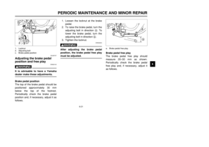
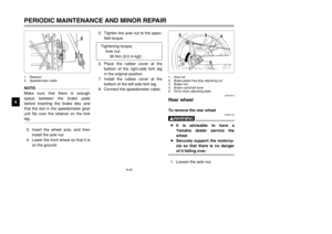
Steering lockSteering lockTo lock the steering
1. Turn the handlebar all the way to
right.
2. Open the steering lock cover,
and then insert the steering lock
key.
3. Turn the key 1/8 turn counter-
clockwise, push it in while turning
the handlebar slightly to the left,
and then turn the key 1/8 turn
clockwise.
21
1. Steering lock cover
2. Steering lock
5RS-9-E0 (TW125) 7/30/01 6:03 PM Page 18
Page 20 of 88
3-9
INSTRUMENT AND CONTROL FUNCTIONS
3
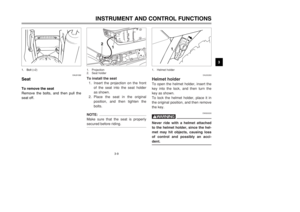
EAU01092
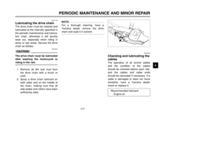
SeatTo remove the seat
Remove the bolts, and then pull the
seat off.
1
1. Bolt (
×2)
EAU00260
Helmet holderTo open the helmet holder, insert the
key into the lock, and then turn the
key as shown.
To lock the helmet holder, place it in
the original position, and then remove
the key.
EW000030
wNever ride with a helmet attached
to the helmet holder, since the hel-
met may hit objects, causing loss
of control and possibly an acci-
dent.
1
1. Helmet holder
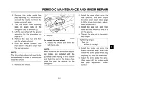
To install the seat
1. Insert the projection on the front
of the seat into the seat holder
as shown.
2. Place the seat in the original
position, and then tighten the
bolts.NOTE:
Make sure that the seat is properly
secured before riding.
1
2
1. Projection
2. Seat holder
5RS-9-E0 (TW125) 7/30/01 6:03 PM Page 19
Page 21 of 88

3-10
INSTRUMENT AND CONTROL FUNCTIONS
3
EAU01343
Shock absorber
EAU00315
wThis shock absorber contains
highly pressurized nitrogen gas.
For proper handling, read and
understand the following informa-
tion before handling the shock
absorber. The manufacturer can-
not be held responsible for proper-
ty damage or personal injury that
may result from improper han-
dling.
8Do not tamper with or attempt
to open the gas cylinder.
8Do not subject the shock
absorber to an open flame or
other high heat sources, other-
wise it may explode due to
excessive gas pressure.
8Do not deform or damage the
gas cylinder in any way, as
this will result in poor damp-
ing performance.
8Always have a Yamaha dealer
service the shock absorber.
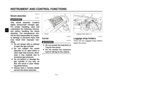
EAU01493
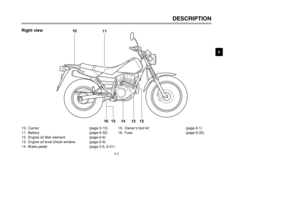
Luggage strap holdersThere are four luggage strap holders
below the carrier.
1
1
1. Luggage strap holder (×4)
EAU00320
Carrier
EW000032
w8Do not exceed the load limit of
3 kg for the carrier.
8Do not exceed the maximum
load of 180 kg for the vehicle.
1
1. Carrier
5RS-9-E0 (TW125) 7/30/01 6:03 PM Page 20
Page 22 of 88

3-11
INSTRUMENT AND CONTROL FUNCTIONS
3
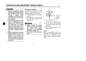
EAU00330
SidestandThe sidestand is located on the left
side of the frame. Raise the side-
stand or lower it with your foot while
holding the motorcycle upright.NOTE:
The built-in sidestand switch is part of
the ignition circuit cut-off system,
which cuts the ignition in certain situ-
ations. (See further down for an
explanation of the ignition circuit cut-
off system.)
EAU03720
Ignition circuit cut-off
systemThe ignition circuit cut-off system
(comprising the sidestand switch,
clutch switch and neutral switch) has
the following functions.
8It prevents starting when the
transmission is in gear and the
sidestand is up, but the clutch
lever is not pulled.
8It prevents starting when the
transmission is in gear and the
clutch lever is pulled, but the
sidestand is still down.
8It cuts the running engine when
the transmission is in gear and
the sidestand is moved down.
Periodically check the operation of
the ignition circuit cut-off system
according to the following procedure.
EW000045
wIf a malfunction is noted, have a
Yamaha dealer check the system
before riding.
EW000044
wThe motorcycle must not be ridden
with the sidestand down, or if the
sidestand cannot be properly
moved up (or does not stay up),
otherwise the sidestand could con-
tact the ground and distract the
operator, resulting in a possible
loss of control. Yamaha’s ignition
circuit cut-off system has been
designed to assist the operator in
fulfilling the responsibility of rais-
ing the sidestand before starting
off. Therefore, check this system
regularly as described below and
have a Yamaha dealer repair it if it
does not function properly.
5RS-9-E0 (TW125) 7/30/01 6:03 PM Page 21
Page 23 of 88

3-12
INSTRUMENT AND CONTROL FUNCTIONS
3
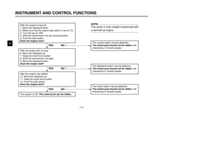
With the engine turned off:
1. Move the sidestand down.
2. Make sure that the engine stop switch is set to “
#”.
3. Turn the key to “ON”.
4. Shift the transmission into the neutral position.
5. Push the start switch.
Does the engine start?
The neutral switch may be defective.
The motorcycle should not be ridden until
checked by a Yamaha dealer.
With the engine still running:
6. Move the sidestand up.
7. Keep the clutch lever pulled.
8. Shift the transmission into gear.
9. Move the sidestand down.
Does the engine stall?After the engine has stalled:
10. Move the sidestand up.
11. Keep the clutch lever pulled.
12. Push the start switch.
Does the engine start?
The sidestand switch may be defective.
The motorcycle should not be ridden until
checked by a Yamaha dealer.The clutch switch may be defective.
The motorcycle should not be ridden until
checked by a Yamaha dealer.
NO
NOTE:This check is most reliable if performed with
a warmed-up engine.
YESYES NO
The system is OK. The motorcycle can be ridden.
YES NO
5RS-9-E0 (TW125) 7/30/01 6:03 PM Page 22
Page 24 of 88

4-1
EAU01114
PRE-OPERATION CHECKS
4 The condition of a vehicle is the owner’s responsibility. Vital components can start to deteriorate quickly and unexpect-
edly, even if the vehicle remains unused (for example, as a result of exposure to the elements). Any damage, fluid leak-
age or loss of tire air pressure could have serious consequences. Therefore, it is very important, in addition to a thor-
ough visual inspection, to check the following points before each ride.
EAU03439
Pre-operation check list
ITEM CHECKS PAGE
Fuel•Check fuel level in fuel tank.
•Refuel if necessary.
•Check fuel line for leakage.3-5–3-6
Engine oil•Check oil level in engine.
•If necessary, add recommended oil to specified level.
•Check vehicle for oil leakage.6-9–6-12
Front brake•Check operation.
•If soft or spongy, have Yamaha dealer bleed hydraulic system.
•Check lever free play.
•Adjust if necessary.
•Check fluid level in reservoir.
•If necessary, add recommended brake fluid to specified level.
•Check hydraulic system for leakage.3-4, 6-20, 6-23–6-25
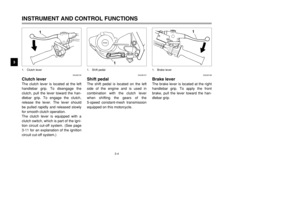
Rear brake•Check operation.
•Check pedal free play.
•Adjust if necessary.3-5, 6-21–6-23
5RS-9-E0 (TW125) 7/30/01 6:03 PM Page 23


EAU00260
Helmet holderTo open the helmet holder, insert the
key in")