Page 9 of 88
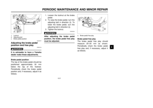
2-1
EAU00026
DESCRIPTION
2
Left view1. Headlight (page 6-34)
2. Steering lock (page 3-8)
3. Fuel tank (page 3-5)
4. Fuel cock (page 3-7)
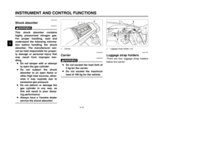
5. Helmet holder (page 3-9)6. Luggage strap holders (page 3-10)
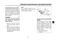
7. Drive chain adjusting plates (page 6-26)
8. Air filter element (page 6-12)
9. Shift pedal (page 3-4)
3
456
7
8 9
1
2
5RS-9-E0 (TW125) 7/30/01 6:02 PM Page 8
Page 10 of 88
2-2
DESCRIPTION
2
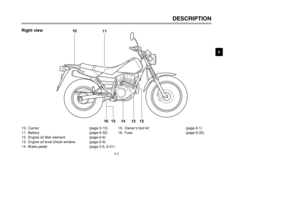
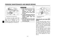
Right view10. Carrier (page 3-10)
11. Battery (page 6-32)
12. Engine oil filter element (page 6-9)
13. Engine oil level check window (page 6-9)
14. Brake pedal (page 3-5, 6-21)15. Owner’s tool kit (page 6-1)
16. Fuse (page 6-33)
10
11
15 14 12
13
16
5RS-9-E0 (TW125) 7/30/01 6:02 PM Page 9
Page 11 of 88
2-3
DESCRIPTION
2
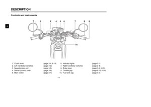
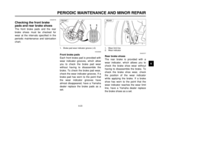
Controls and instruments1. Clutch lever (page 3-4, 6-19)
2. Left handlebar switches (page 3-2)
3. Speedometer unit (page 3-2)
4. Starter (choke) knob (page 3-8)
5. Main switch (page 3-1)6. Indicator lights (page 3-1)
7. Right handlebar switches (page 3-3)
8. Brake lever (page 3-4, 6-20)
9. Throttle grip (page 6-15, 6-28)
10. Fuel tank cap (page 3-5)
1
23
45
678
9
10
5RS-9-E0 (TW125) 7/30/01 6:02 PM Page 10
Page 12 of 88
3-1
EAU00027
INSTRUMENT AND CONTROL FUNCTIONS
3
EAU00028
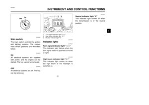
Main switchMain switchThe main switch controls the ignition
and lighting systems. The various
main switch positions are described
below.
EAU00036
ON
All electrical systems are supplied
with power, and the engine can be
started. The key cannot be removed.
EAU00038
OFF
All electrical systems are off. The key
can be removed.
EAU00061
Neutral indicator light “N”
This indicator light comes on when
the transmission is in the neutral
position.
OFFON
EAU00056
Indicator lights
EAU00057
Turn signal indicator light “
5”
This indicator light flashes when the
turn signal switch is pushed to the left
or right.
EAU00063
High beam indicator light “&”
This indicator light comes on when
the high beam of the headlight is
switched on.
3
12
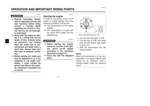
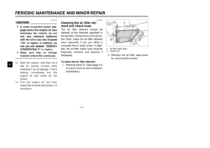
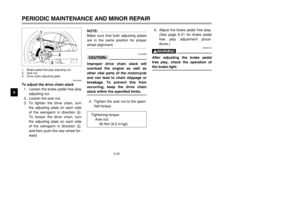
1. Turn signal indicator light “5”
2. High beam indicator light “&”
3. Neutral indicator light “N”
5RS-9-E0 (TW125) 7/30/01 6:02 PM Page 11
Page 13 of 88

3-2
EAU01087
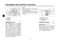
Speedometer unit The speedometer unit is equipped
with a speedometer, an odometer
and a tripmeter. The speedometer
shows riding speed. The odometer
shows the total distance traveled.
The tripmeter shows the distance
traveled since it was last set to zero
with the reset knob. The tripmeter
can be used to estimate the distance
that can be traveled with a full tank of
fuel. This information will enable you
to plan future fuel stops.
NOTE:
Only for the German model equipped
with a speed limiter:
The speed limiter prevents the motor-
cycle from exceeding a riding speed
of 80 km/h.
INSTRUMENT AND CONTROL FUNCTIONS
3
4
1
23
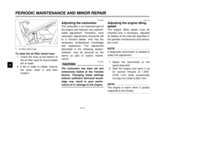
1. Speedometer
2. Odometer
3. Tripmeter
4. Reset knob
EAU00118
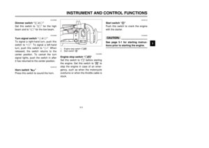
Handlebar switches
EAU03898
Light switch “9/
'
/:”
Set this switch to “'
” to turn on
the auxiliary light, meter lighting and
taillight. Set the switch to “:” to turn
on the headlight also. Set the switch
to “9” to turn off all the lights.
41
2
3
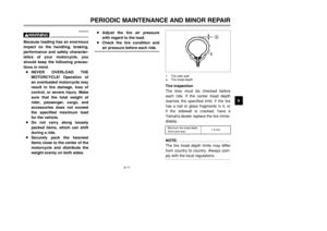
1. Light switch “9/
'
/:”
2. Dimmer switch “&/%”
3. Turn signal switch “4/6”
4. Horn switch “*”
5RS-9-E0 (TW125) 7/30/01 6:03 PM Page 12
Page 14 of 88
3-3
INSTRUMENT AND CONTROL FUNCTIONS
3
EAU03888
Dimmer switch “&/%”
Set this switch to “&” for the high
beam and to “%” for the low beam.
EAU03889
Turn signal switch “4/6”
To signal a right-hand turn, push this
switch to “6”. To signal a left-hand
turn, push this switch to “4”. When
released, the switch returns to the
center position. To cancel the turn
signal lights, push the switch in after
it has returned to the center position.
EAU00129
Horn switch “*”
Press this switch to sound the horn.
EAU00143
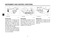
Start switch “,”
Push this switch to crank the engine
with the starter.
EC000005
cCSee page 5-1 for starting instruc-
tions prior to starting the engine.
EAU03890
Engine stop switch “#/$”
Set this switch to “#” before starting
the engine. Set this switch to “$” to
stop the engine in case of an emer-
gency, such as when the motorcycle
overturns or when the throttle cable is
stuck.
1
2
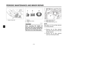
1. Engine stop switch “#/$”
2. Start switch “,”
5RS-9-E0 (TW125) 7/30/01 6:03 PM Page 13
Page 15 of 88
3-4
EAU00152
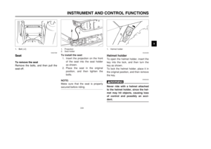
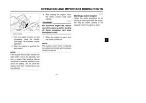
Clutch leverThe clutch lever is located at the left
handlebar grip. To disengage the
clutch, pull the lever toward the han-
dlebar grip. To engage the clutch,
release the lever. The lever should
be pulled rapidly and released slowly
for smooth clutch operation.
The clutch lever is equipped with a
clutch switch, which is part of the igni-
tion circuit cut-off system. (See page
3-11 for an explanation of the ignition
circuit cut-off system.)INSTRUMENT AND CONTROL FUNCTIONS
3
1
1. Clutch lever
EAU00158
Brake leverThe brake lever is located at the right
handlebar grip. To apply the front
brake, pull the lever toward the han-
dlebar grip.
1
1. Brake lever
EAU00157
Shift pedalThe shift pedal is located on the left
side of the engine and is used in
combination with the clutch lever
when shifting the gears of the
5-speed constant-mesh transmission
equipped on this motorcycle.
1
1. Shift pedal
5RS-9-E0 (TW125) 7/30/01 6:03 PM Page 14
Page 16 of 88
3-5
INSTRUMENT AND CONTROL FUNCTIONS
3
EAU00162
Brake pedalThe brake pedal is on the right side
of the motorcycle. To apply the rear
brake, press down on the brake
pedal.
1
1. Brake pedal
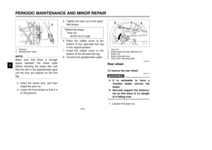
To install the fuel tank cap
1. Insert the fuel tank cap into the
tank opening with the key insert-
ed in the lock, and then turn the
cap 1/3 turn clockwise.
2. Turn the key 1/4 turn clockwise,
and then remove it.NOTE:
The fuel tank cap cannot be installed
unless the key is in the lock. In addi-
tion, the key cannot be removed if the
cap is not properly installed and
locked.
EW000023
wMake sure that the fuel tank cap is
properly closed and locked before
riding.
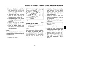
EAU00177
Fuel tank capTo remove the fuel tank cap
1. Insert the key into the lock and
turn it 1/4 turn counterclockwise.
2. Turn the fuel tank cap 1/3 turn
counterclockwise and pull it off.
1 b
a
1. Fuel tank cap
a. Unlock.
b. Open.
5RS-9-E0 (TW125) 7/30/01 6:03 PM Page 15


2. Steering lock (page 3-8)
3. Fuel tank (page 3-5)
4. Fuel cock (page 3-7)
5. Helmet holder (page 3-9)6. Luggage strap holders (page 3")

11. Battery (page 6-32)
12. Engine oil filter element (page 6-9)
13. Engine oil level check window (page 6-9)
14. Brake pedal (page 3-5, 6-21)15.")

2. Left handlebar switches (page 3-2)
3. Speedometer unit (page 3-2)
4. Starter (choke) knob (page 3-8)
5. Main switch (pa")


