Page 9 of 94
2-1
EAU00026
DESCRIPTION
2
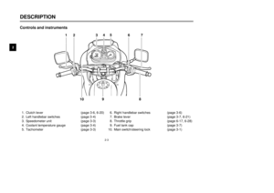
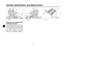
1. Headlight (page 6-34)
2. Fuel cock (page 3-11)
3. 2-stroke engine oil tank (page 3-10)
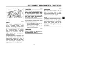
4. Helmet holder (page 3-13)
5. Starter (choke) lever (page 3-12)6. YEIS (page 3-14)
7. YPVS (page 3-15)
12
34
5
6 7
Left view
5AE-28199-E5 honbun 7/6/01 10:18 AM Page 8
Page 10 of 94
2-2
DESCRIPTION
2
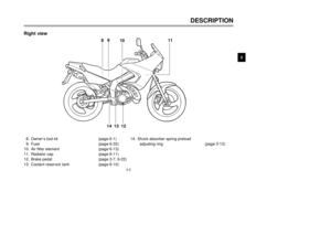
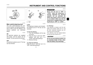
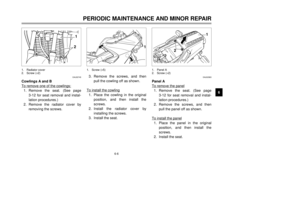
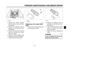
8. Owner’s tool kit (page 6-1)
9. Fuse (page 6-33)
10. Air filter element (page 6-13)
11. Radiator cap (page 6-11)
12. Brake pedal (page 3-7, 6-22)
13. Coolant reservoir tank (page 6-10)14. Shock absorber spring preload
adjusting ring (page 3-13)
89
1011
12
13 14
Right view
5AE-28199-E5 honbun 7/6/01 10:18 AM Page 9
Page 11 of 94
2-3
DESCRIPTION
2
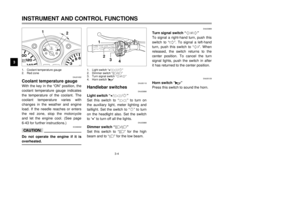
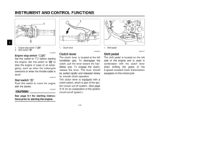
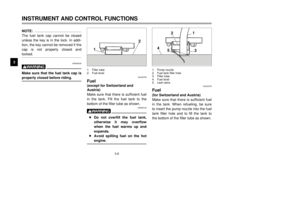
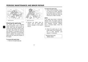
1. Clutch lever (page 3-6, 6-20)
2. Left handlebar switches (page 3-4)
3. Speedometer unit (page 3-3)
4. Coolant temperature gauge (page 3-4)
5. Tachometer (page 3-3)6. Right handlebar switches (page 3-6)
7. Brake lever (page 3-7, 6-21)
8. Throttle grip (page 6-17, 6-28)
9. Fuel tank cap (page 3-7)
10. Main switch/steering lock (page 3-1)
1
2345
67
8 9
10
Controls and instruments
5AE-28199-E5 honbun 7/6/01 10:18 AM Page 10
Page 12 of 94

3-1
EAU00027
INSTRUMENT AND CONTROL FUNCTIONS
3
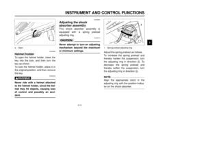
EAU00029
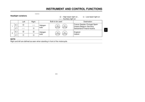
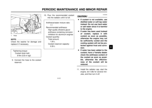
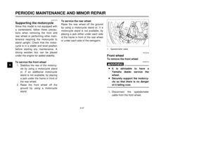
Main switch/steering lockThe main switch/steering lock con-
trols the ignition and lighting systems,
and is used to lock the steering. The
various positions are described
below.
EAU00036
ON
All electrical systems are supplied
with power, and the engine can be
started. The key cannot be removed.
EAU00038
OFF
All electrical systems are off. The key
can be removed.
EAU00040
LOCK
The steering is locked, and all electri-
cal systems are off. The key can be
removed.
To lock the steering1. Turn the handlebars all the way
to the left.
2. Push the key in from the “OFF”
position, and then turn it to
“LOCK” while still pushing it.
3. Remove the key.
To unlock the steeringPush the key in, and then turn it to
“OFF” while still pushing it.
EW000016
wNever turn the key to “OFF” or
“LOCK” while the motorcycle is
moving, otherwise the electrical
systems will be switched off,
which may result in loss of control
or an accident. Make sure that the
motorcycle is stopped before turn-
ing the key to “OFF” or “LOCK”.
EAU01574
.
.
(Parking)
The steering is locked, and the tail-
lights and auxiliary lights are on, but
all other electrical systems are off.
The key can be removed.
The steering must be locked before
the key can be turned to “
.
”.
ECA00043
cCDo not use the parking position for
an extended length of time, other-
wise the battery may discharge.
OFFON
LOCKPPUSH
YM-8
IGNITION
ON
OFF
LOCK
PARKING
a
b
a. Push.
b. Turn.
5AE-28199-E5 honbun 7/6/01 10:18 AM Page 11
Page 13 of 94

3-2
EAU03034
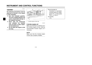
Indicator and warning lights
EAU00057
Turn signal indicator light “5”
This indicator light flashes when the
turn signal switch is pushed to the left
or right.
EAU00063
High beam indicator light “&”
This indicator light comes on when
the high beam of the headlight is
switched on.
EAU04304
2-stroke engine oil level warning
light “
7
”
This warning light comes on when
the 2-stroke engine oil level is low.
The electrical circuit of the warning
light can be checked according to the
following procedure.
1. Set the engine stop switch to
"#" and turn the key to "ON".
2. Shift the transmission into the
neutral position or pull the clutch
lever.
3. Push the start switch. If the
warning light does not come on
while pushing the start switch,
have a Yamaha dealer check the
electrical circuit.
NOTE:
Even if the 2-stroke engine oil level is
sufficient, the warning light may flick-
er when riding on a slope or during
sudden acceleration or deceleration,
but this is not a malfunction.
EAU00061
Neutral indicator light “N”
This indicator light comes on when
the transmission is in the neutral
position.
INSTRUMENT AND CONTROL FUNCTIONS
3
1
2
3
4
1. Turn signal indicator light “5”
2. High beam indicator light “&”
3. 2-stroke enjine oil level warning light “
7
”
4. Neutral indicator light “N”
5AE-28199-E5 honbun 7/6/01 10:18 AM Page 12
Page 14 of 94
3-3
INSTRUMENT AND CONTROL FUNCTIONS
3
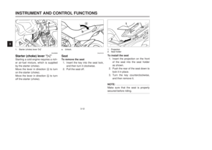
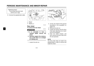
EAU01087
Speedometer unitThe speedometer unit is equipped
with a speedometer, an odometer
and a tripmeter. The speedometer
shows riding speed. The odometer
shows the total distance traveled.
The tripmeter shows the distance
traveled since it was last set to zero
with the reset knob. The tripmeter
can be used to estimate the distance
that can be traveled with a full tank of
fuel. This information will enable you
to plan future fuel stops.
NOTE:
Only for the German model equipped
with a speed limiter:
The speed limiter prevents the motor-
cycle from exceeding a riding speed
of 80 km/h.
EAU00102
TachometerThe tachometer allows the rider to
monitor the engine speed and keep it
within the ideal power range.
EC000003
cCDo not operate the engine in the
tachometer red zone.
Red zone: 10,000 r/min and above
12
3 4
1
2
1. Speedometer
2. Odometer
3. Tripmeter
4. Reset knob1. Tachometer
2. Red zone
5AE-28199-E5 honbun 7/6/01 10:18 AM Page 13
Page 15 of 94

3-4
EAU01652
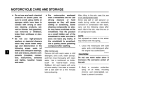
Coolant temperature gaugeWith the key in the “ON” position, the
coolant temperature gauge indicates
the temperature of the coolant. The
coolant temperature varies with
changes in the weather and engine
load. If the needle reaches or enters
the red zone, stop the motorcycle
and let the engine cool. (See page
6-43 for further instructions.)
EC000002
cCDo not operate the engine if it is
overheated.
EAU00118
Handlebar switches
EAU03898
Light switch “
9/
'
/:”
Set this switch to “'
” to turn on
the auxiliary light, meter lighting and
taillight. Set the switch to “:” to turn
on the headlight also. Set the switch
to “
9” to turn off all the lights.
EAU03888
Dimmer switch “&/%”
Set this switch to “&” for the high
beam and to “%” for the low beam.
EAU03889
Turn signal switch “4/6”
To signal a right-hand turn, push this
switch to “6”. To signal a left-hand
turn, push this switch to “4”. When
released, the switch returns to the
center position. To cancel the turn
signal lights, push the switch in after
it has returned to the center position.
EAU00129
Horn switch “*”
Press this switch to sound the horn.
INSTRUMENT AND CONTROL FUNCTIONS
3
2 1
1
2
3
4
1. Coolant temperature gauge
2. Red zone1. Light switch “
9/
'
/:”
2. Dimmer switch “&/%”
3. Turn signal switch “4/6”
4. Horn switch “*”
5AE-28199-E5 honbun 7/6/01 10:18 AM Page 14
Page 16 of 94
3-5
INSTRUMENT AND CONTROL FUNCTIONS
3
EAU00136
Headlight variationsNOTE:
Right and left are defined as seen when standing in front of the motorcycle.
3 : High beam light on , 2: Low beam light on'
: Auxiliary light on
1
2
&
&%
%
Left RightBulb to be used
Destination3'3
2
'2
3
2
Halogen
bulb
Halogen
bulbFrance Sweden Portugal Spain
Greece Belgium Germany
Switzerland Finland Austria
England
Ireland
12V
60/55W
12V
60/55W
12V
35/35W
12V
35/35W
5AE-28199-E5 honbun 7/6/01 10:18 AM Page 15


2. Fuel cock (page 3-11)
3. 2-stroke engine oil tank (page 3-10)
4. Helmet holder (page 3-13)
5. Starter (choke) lever (page 3-12)6. YEIS (page")

9. Fuse (page 6-33)
10. Air filter element (page 6-13)
11. Radiator cap (page 6-11)
12. Brake pedal (page 3-7, 6-22)
13. Coolant reservoir tank (")

2. Left handlebar switches (page 3-4)
3. Speedometer unit (page 3-3)
4. Coolant temperature gauge (page 3-4)
5. Tachometer (page 3-3)6. Right hand")

