Page 49 of 94

6-13
PERIODIC MAINTENANCE AND MINOR REPAIR
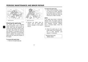
612. Remove the radiator cap to
check the coolant level in the
radiator. If necessary, add suffi-
cient coolant until it reaches the
top of the radiator, and then
install the radiator cap.
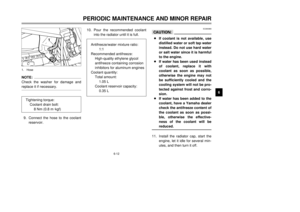
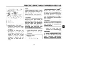
13. Check the coolant level in the
reservoir. If necessary, remove
the coolant reservoir cap by
removing the screw and retainer,
add coolant to the maximum
level mark, and then install the
coolant reservoir cap and retain-
er by installing the screw.14. Start the engine, and then check
the vehicle for coolant leakage. If
coolant is leaking, have a
Yamaha dealer check the cool-
ing system.
15. Install the cowling and the seat.
EAU03747
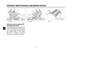
Cleaning the air filter
elementThe air filter element should be
cleaned at the intervals specified in
the periodic maintenance and lubrica-
tion chart. Clean the air filter element
more frequently if you are riding in
unusually wet or dusty areas.
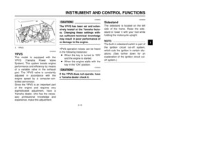
1. Remove the seat. (See page
3-12 for seat removal and instal-
lation procedures.)
2. Remove cowlings A and B. (See
page 6-6 for cowling removal
and installation procedures.)
3. Remove the fuel tank bolt.
21
4
5
3
1
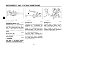
1. Coolant reservoir tank cap
2. Retainer
3. Screw
4. Maximum level mark
5. Minimum level mark1. Bolt
5AE-28199-E5 honbun 7/6/01 10:18 AM Page 48
Page 50 of 94
6-14
PERIODIC MAINTENANCE AND MINOR REPAIR
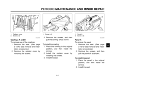
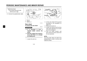
6 4. Lift the front of the fuel tank to
position the fuel tank away from
the air filter case. (Do not discon-
nect the fuel hoses!)
EW000071
w8Make sure that the fuel tank is
well supported.
8Do not tilt or pull the fuel tank
too much, otherwise the fuel
hoses may come loose, which
could cause fuel leakage.
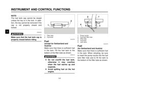
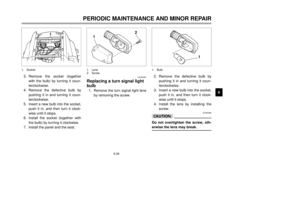
5. Remove the relays by pulling
them off their holders, and the air
filter case cover by removing the
screws.6. Pull the sponge material out,
clean it with solvent, and then
squeeze the remaining solvent
out.
7. Apply oil of the recommended
type to the entire surface of the
sponge material, and then
squeeze the excess oil out.
NOTE:
The sponge material should be wet
but not dripping.
1
3
3
2
1
1. Relay (×2)
2. Air filter case cover
3. Screw (×7)1. Sponge material
Recommended oil:
2-stroke engine oil
5AE-28199-E5 honbun 7/6/01 10:18 AM Page 49
Page 51 of 94

6-15
PERIODIC MAINTENANCE AND MINOR REPAIR
68. Insert the sponge material into
the air filter case.
EC000082
cC8Make sure that the air filter ele-
ment is properly seated in the
air filter case.
8The engine should never be
operated without the air filter
element installed, otherwise
the piston and/or cylinder may
become excessively worn.9. Install the air filter case cover by
installing the screws, and then
install the relays.
10. Place the fuel tank in the original
position, and then install the bolt.
EW000131
wMake sure that the fuel hoses and
vacuum hose are properly con-
nected and routed, and not
pinched. Replace any damaged
hoses.11. Install the seat and the cowlings.
EAU00629
Adjusting the carburetorThe carburetor is an important part of
the engine and requires very sophisti-
cated adjustment. Therefore, most
carburetor adjustments should be left
to a Yamaha dealer, who has the
necessary professional knowledge
and experience. The adjustment
described in the following section,
however, may be serviced by the
owner as part of routine mainte-
nance.
EC000094
cCThe carburetor has been set and
extensively tested at the Yamaha
factory. Changing these settings
without sufficient technical knowl-
edge may result in poor perfor-
mance of or damage to the engine.
5AE-28199-E5 honbun 7/6/01 10:18 AM Page 50
Page 52 of 94
6-16
PERIODIC MAINTENANCE AND MINOR REPAIR
6
EAU00632
Adjusting the engine idling
speedThe engine idling speed must be
checked and, if necessary, adjusted
as follows at the intervals specified in
the periodic maintenance and lubrica-
tion chart.
1. Start the engine and warm it up
for several minutes at
1,000–2,000 r/min while occa-
sionally revving it to 4,000–5,000
r/min.NOTE:
The engine is warm when it quickly
responds to the throttle.
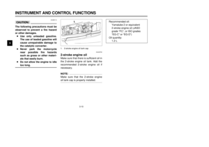
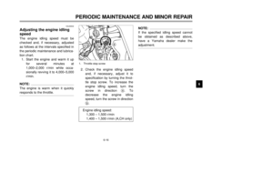
2. Check the engine idling speed
and, if necessary, adjust it to
specification by turning the throt-
tle stop screw. To increase the
engine idling speed, turn the
screw in direction a. To
decrease the engine idling
speed, turn the screw in direction
b.
NOTE:
If the specified idling speed cannot
be obtained as described above,
have a Yamaha dealer make the
adjustment.
ba
1
1. Throttle stop screw
Engine idling speed:
1,300 – 1,500 r/min
1,400 – 1,500 r/min (A,CH only)
5AE-28199-E5 honbun 7/6/01 10:18 AM Page 51
Page 53 of 94

6-17
PERIODIC MAINTENANCE AND MINOR REPAIR
6
EAU00634
Adjusting the throttle cable
free playThe throttle cable free play should
measure 3–5 mm at the throttle grip.
Periodically check the throttle cable
free play and, if necessary, adjust it
as follows.NOTE:
The engine idling speed must be cor-
rectly adjusted before checking and
adjusting the throttle cable free play.
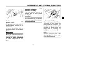
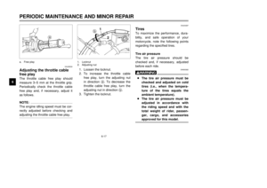
1. Loosen the locknut.
2. To increase the throttle cable
free play, turn the adjusting nut
in direction a. To decrease the
throttle cable free play, turn the
adjusting nut in direction b.
3. Tighten the locknut.
EAU04287
TiresTo maximize the performance, dura-
bility, and safe operation of your
motorcycle, note the following points
regarding the specified tires.
Tire air pressure
The tire air pressure should be
checked and, if necessary, adjusted
before each ride.
EW000082
w8The tire air pressure must be
checked and adjusted on cold
tires (i.e., when the tempera-
ture of the tires equals the
ambient temperature).
8The tire air pressure must be
adjusted in accordance with
the riding speed and with the
total weight of rider, passen-
ger, cargo, and accessories
approved for this model.
a
2 1
b
a
a. Free play 1. Locknut
2. Adjusting nut
5AE-28199-E5 honbun 7/6/01 10:18 AM Page 52
Page 54 of 94

6-18
PERIODIC MAINTENANCE AND MINOR REPAIR
6
EWA00012
wBecause loading has an enormous
impact on the handling, braking,
performance and safety character-
istics of your motorcycle, you
should keep the following precau-
tions in mind.
8NEVER OVERLOAD THE
MOTORCYCLE! Operation of
an overloaded motorcycle may
result in tire damage, loss of
control, or severe injury. Make
sure that the total weight of
rider, passenger, cargo, and
accessories does not exceed
the specified maximum load
for the vehicle.
8Do not carry along loosely
packed items, which can shift
during a ride.
8Securely pack the heaviest
items close to the center of the
motorcycle and distribute the
weight evenly on both sides.
8Adjust the suspension and tire
air pressure with regard to the
load.
8Check the tire condition and
air pressure before each ride.
Tire inspection
The tires must be checked before
each ride. If the center tread depth
reaches the specified limit, if the tire
has a nail or glass fragments in it, or
if the sidewall is cracked, have a
Yamaha dealer replace the tire imme-
diately.NOTE:
The tire tread depth limits may differ
from country to country. Always com-
ply with the local regulations.
1a
1. Tire side wall
a. Tread depth
Tire air pressure
(measured on cold tires)
Load* Front Rear
Up to 90 kg175 kPa
(1.75 kgf/cm
2,
1.75 bar)200 kPa
(2.00 kgf/cm
2,
2.00 bar)
90 kg–maximum175 kPa
(1.75 kgf/cm
2,
1.75 bar)225 kPa
(2.25 kgf/cm
2,
2.25 bar)
Maximum load*180 kg
179 kg (CH, A)
* Total weight of rider, passenger, cargo and
accessories
Minimum tire tread depth
(front and rear)1.6 mm
5AE-28199-E5 honbun 7/6/01 10:18 AM Page 53
Page 55 of 94

6-19
PERIODIC MAINTENANCE AND MINOR REPAIR
6Tire information
This motorcycle is equipped with cast
wheel and tubeless tires.
EW000078
w8The front and rear tires should
be of the same make and
design, otherwise the handling
characteristics of the motorcy-
cle cannot be guaranteed.
8After extensive tests, only the
tires listed below have been
approved for this model by
Yamaha Motor Co., Ltd.
EAU00683
w8Have a Yamaha dealer replace
excessively worn tires.
Besides being illegal, operat-
ing the motorcycle with exces-
sively worn tires decreases
riding stability and can lead to
loss of control.
8The replacement of all wheel-
and brake-related parts,
including the tires, should be
left to a Yamaha dealer, who
has the necessary profession-
al knowledge and experience.
FRONT
Manufacturer Size TypeBRIDGESTONE
100/90-18 56P
TW53
100/90-18 M/C 56P
DUNLOP
100/90-18 56P
D602F
100/90-18 M/C 56P
REAR
Manufacturer Size Type
BRIDGESTONE
130/80-17 65P
TW54
130/80-17 M/C 65P
DUNLOP130/80-17 65P
D602
130/80-17 M/C 65P
EAU03773
Cast wheelsTo maximize the performance, dura-
bility, and safe operation of your
motorcycle, note the following points
regarding the specified wheels.
8The wheel rims should be
checked for cracks, bends or
warpage before each ride. If any
damage is found, have a
Yamaha dealer replace the
wheel. Do not attempt even the
smallest repair to the wheel. A
deformed or cracked wheel must
be replaced.
8The wheel should be balanced
whenever either the tire or wheel
has been changed or replaced.
An unbalanced wheel can result
in poor performance, adverse
handling characteristics, and a
shortened tire life.
8Ride at moderate speeds after
changing a tire since the tire sur-
face must first be “broken in” for
it to develop its optimal charac-
teristics.
5AE-28199-E5 honbun 7/6/01 10:18 AM Page 54
Page 56 of 94

6-20
PERIODIC MAINTENANCE AND MINOR REPAIR
6
EAU00694
Adjusting the clutch lever
free playThe clutch lever free play should
measure 10–15 mm as shown.
Periodically check the clutch lever
free play and, if necessary, adjust it
as follows.
1. Loosen the locknut at the clutch
lever.
2. To increase the clutch lever free
play, turn the adjusting bolt in
direction a. To decrease the
clutch lever free play, turn the
adjusting bolt in direction b.3. If the specified clutch lever free
play could be obtained as
described above, tighten the
locknut and skip the rest of the
procedure, otherwise proceed as
follows.
4. Fully turn the adjusting bolt at the
clutch lever in direction ato
loosen the clutch cable.
5. Loosen the locknut at the
crankcase.
6. To increase the clutch lever free
play, turn the adjusting nut in
direction a. To decrease the
clutch lever free play, turn the
adjusting nut in direction b.
ab
12 c
ba
1
2
1. Locknut (clutch lever)
2. Adjusting bolt
c. Free play1. Locknut (crankcase)
2. Adjusting nut
7. Tighten the locknut at the clutch
lever and the crankcase.
5AE-28199-E5 honbun 7/6/01 10:18 AM Page 55


EW000071
w8Make sure that")
