2002 YAMAHA TDR 125 lights
[x] Cancel search: lightsPage 6 of 94
EAU00009
TABLE OF CONTENTS
GIVE SAFETY THE RIGHT OF WAY ............... 1-1
DESCRIPTION .................................................. 2-1
Left view ......................................................... 2-1
Right view ...................................................... 2-2
Controls and instruments ............................... 2-3INSTRUMENT AND CONTROL FUNCTIONS
..... 3-1
Main switch/steering lock ............................... 3-1
Indicator and warning lights ........................... 3-2
Speedometer unit ........................................... 3-3
Tachometer .................................................... 3-3
Coolant temperature gauge ........................... 3-4
Handlebar switches ........................................ 3-4
Clutch lever .................................................... 3-6
Shift pedal ...................................................... 3-6
Brake lever ..................................................... 3-7
Brake pedal .................................................... 3-7
Fuel tank cap ................................................. 3-7
Fuel (except for Switzerland and Austria) ...... 3-8
Fuel (for Switzerland and Austria)................... 3-8
Catalytic converter
(for Switzerland and Austria) ........................ 3-9
2-stroke engine oil ........................................ 3-10
Fuel cock ...................................................... 3-11
Starter (choke) lever .................................... 3-12
Seat .............................................................. 3-12Helmet holder ............................................... 3-13
Adjusting the shock absorber assembly ........3-13
YEIS handling precautions ........................... 3-14
YPVS ........................................................... 3-15
Sidestand ..................................................... 3-15
Ignition circuit cut-off system ........................ 3-16
PRE-OPERATION CHECKS ............................ 4-1
Pre-operation check list ................................. 4-1
OPERATION AND IMPORTANT RIDING
POINTS ............................................................. 5-1
Starting a cold engine .................................... 5-1
Starting a warm engine .................................. 5-2
Shifting ........................................................... 5-3
Recommended shift points
(for Switzerland only) ................................... 5-3
Tips for reducing fuel consumption ............... 5-4
Engine break-in .............................................. 5-4
Parking ........................................................... 5-5
PERIODIC MAINTENANCE AND MINOR
REPAIR ............................................................. 6-1
Owner’s tool kit .............................................. 6-1
Periodic maintenance and lubrication chart ... 6-2
Removing and installing the cowlings and
panel ............................................................ 6-5
123
456
5AE-28199-E5 honbun 7/6/01 10:18 AM Page 5
Page 12 of 94
3-1
EAU00027
INSTRUMENT AND CONTROL FUNCTIONS
3
EAU00029
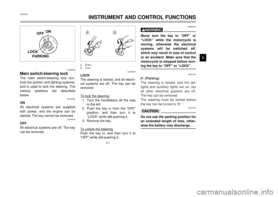
Main switch/steering lockThe main switch/steering lock con-
trols the ignition and lighting systems,
and is used to lock the steering. The
various positions are described
below.
EAU00036
ON
All electrical systems are supplied
with power, and the engine can be
started. The key cannot be removed.
EAU00038
OFF
All electrical systems are off. The key
can be removed.
EAU00040
LOCK
The steering is locked, and all electri-
cal systems are off. The key can be
removed.
To lock the steering1. Turn the handlebars all the way
to the left.
2. Push the key in from the “OFF”
position, and then turn it to
“LOCK” while still pushing it.
3. Remove the key.
To unlock the steeringPush the key in, and then turn it to
“OFF” while still pushing it.
EW000016
wNever turn the key to “OFF” or
“LOCK” while the motorcycle is
moving, otherwise the electrical
systems will be switched off,
which may result in loss of control
or an accident. Make sure that the
motorcycle is stopped before turn-
ing the key to “OFF” or “LOCK”.
EAU01574
.
.
(Parking)
The steering is locked, and the tail-
lights and auxiliary lights are on, but
all other electrical systems are off.
The key can be removed.
The steering must be locked before
the key can be turned to “
.
”.
ECA00043
cCDo not use the parking position for
an extended length of time, other-
wise the battery may discharge.
OFFON
LOCKPPUSH
YM-8
IGNITION
ON
OFF
LOCK
PARKING
a
b
a. Push.
b. Turn.
5AE-28199-E5 honbun 7/6/01 10:18 AM Page 11
Page 13 of 94
3-2
EAU03034
Indicator and warning lights
EAU00057
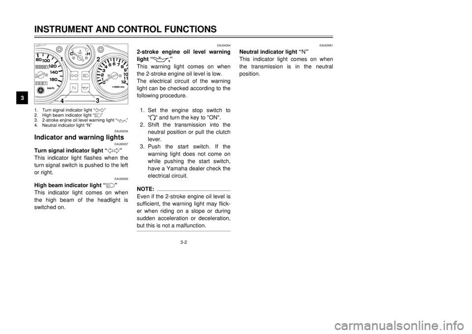
Turn signal indicator light “5”
This indicator light flashes when the
turn signal switch is pushed to the left
or right.
EAU00063
High beam indicator light “&”
This indicator light comes on when
the high beam of the headlight is
switched on.
EAU04304
2-stroke engine oil level warning
light “
7
”
This warning light comes on when
the 2-stroke engine oil level is low.
The electrical circuit of the warning
light can be checked according to the
following procedure.
1. Set the engine stop switch to
"#" and turn the key to "ON".
2. Shift the transmission into the
neutral position or pull the clutch
lever.
3. Push the start switch. If the
warning light does not come on
while pushing the start switch,
have a Yamaha dealer check the
electrical circuit.
NOTE:
Even if the 2-stroke engine oil level is
sufficient, the warning light may flick-
er when riding on a slope or during
sudden acceleration or deceleration,
but this is not a malfunction.
EAU00061
Neutral indicator light “N”
This indicator light comes on when
the transmission is in the neutral
position.
INSTRUMENT AND CONTROL FUNCTIONS
3
1
2
3
4
1. Turn signal indicator light “5”
2. High beam indicator light “&”
3. 2-stroke enjine oil level warning light “
7
”
4. Neutral indicator light “N”
5AE-28199-E5 honbun 7/6/01 10:18 AM Page 12
Page 15 of 94
3-4
EAU01652
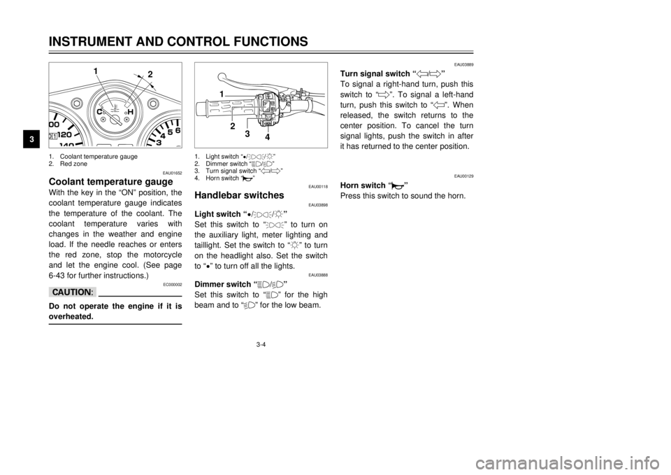
Coolant temperature gaugeWith the key in the “ON” position, the
coolant temperature gauge indicates
the temperature of the coolant. The
coolant temperature varies with
changes in the weather and engine
load. If the needle reaches or enters
the red zone, stop the motorcycle
and let the engine cool. (See page
6-43 for further instructions.)
EC000002
cCDo not operate the engine if it is
overheated.
EAU00118
Handlebar switches
EAU03898
Light switch “
9/
'
/:”
Set this switch to “'
” to turn on
the auxiliary light, meter lighting and
taillight. Set the switch to “:” to turn
on the headlight also. Set the switch
to “
9” to turn off all the lights.
EAU03888
Dimmer switch “&/%”
Set this switch to “&” for the high
beam and to “%” for the low beam.
EAU03889
Turn signal switch “4/6”
To signal a right-hand turn, push this
switch to “6”. To signal a left-hand
turn, push this switch to “4”. When
released, the switch returns to the
center position. To cancel the turn
signal lights, push the switch in after
it has returned to the center position.
EAU00129
Horn switch “*”
Press this switch to sound the horn.
INSTRUMENT AND CONTROL FUNCTIONS
3
2 1
1
2
3
4
1. Coolant temperature gauge
2. Red zone1. Light switch “
9/
'
/:”
2. Dimmer switch “&/%”
3. Turn signal switch “4/6”
4. Horn switch “*”
5AE-28199-E5 honbun 7/6/01 10:18 AM Page 14
Page 31 of 94

4-3
PRE-OPERATION CHECKS
4
NOTE:
Pre-operation checks should be made each time the motorcycle is used. Such an inspection can be accomplished in a
very short time; and the added safety it assures is more than worth the time involved.
EWA00033
wIf any item in the Pre-operation check list is not working properly, have it inspected and repaired before operat-
ing the motorcycle.Chassis fasteners•Make sure that all nuts, bolts and screws are properly tightened.
•Tighten if necessary.—
Instruments, lights, signals
and switches•Check operation.
•Correct if necessary.3-2–3-6
Sidestand switch•Check operation of ignition circuit cut-off system.
•If system is defective, have Yamaha dealer check vehicle.3-15–3-17 ITEM CHECKS PAGE
5AE-28199-E5 honbun 7/6/01 10:18 AM Page 30
Page 35 of 94
5-4
OPERATION AND IMPORTANT RIDING POINTS
5
EAU00424
Tips for reducing fuel
consumptionFuel consumption depends largely on
your riding style. Consider the follow-
ing tips to reduce fuel consumption:
8Thoroughly warm up the engine.
8Turn the starter (choke) off as
soon as possible.
8Shift up swiftly, and avoid high
engine speeds during accelera-
tion.
8Do not rev the engine while shift-
ing down, and avoid high engine
speeds with no load on the
engine.
8Turn the engine off instead of let-
ting it idle for an extended length
of time (e.g., in traffic jams, at
traffic lights or at railroad cross-
ings).
EAU00436
Engine break-inThere is never a more important peri-
od in the life of your engine than the
period between 0 and 1,000 km. For
this reason, you should read the fol-
lowing material carefully.
Since the engine is brand new, do
not put an excessive load on it for the
first 1,000 km. The various parts in
the engine wear and polish them-
selves to the correct operating clear-
ances. During this period, prolonged
full-throttle operation or any condition
that might result in engine overheat-
ing must be avoided.
EAU00453
0–500 km
8Avoid prolonged operation above
6,000 r/min.
8After every hour of operation,
stop the engine, and then let it
cool for five to ten minutes.
8Vary the engine speed from time
to time. Do not operate the
engine at one set throttle posi-
tion.
500–1,000 km
8Avoid prolonged operation
above 7,000 r/min.
8Rev the engine freely through
the gears, but do not use full
throttle at any time.
EC000060
cCAfter 1,000 km of operation, the
transmission oil must be changed.
5AE-28199-E5 honbun 7/6/01 10:18 AM Page 34
Page 40 of 94

6-4
PERIODIC MAINTENANCE AND MINOR REPAIR
6
EAU03884
NOTE:
8The air filter needs more frequent service if you are riding in unusually wet or dusty areas.
8Hydraulic brake service
9Regularly check and, if necessary, correct the brake fluid level.
9Every two years replace the internal components of the brake master cylinders and calipers, and change the
brake fluid.
9Replace the brake hoses every four years and if cracked or damaged.21 Transmission oil•Check oil level.√√√√√ √
•Change.√√
22
*Cooling system•Check coolant level and vehicle for coolant leakage.√√√√ √
•Change.Every 3 years
23*Front and rear brake
switches•Check operation.√√√√√ √
24 Moving parts and cables•Lubricate.√√√√ √
25*Lights, signals and
switches•Check operation.
•Adjust headlight beam.√√√√√ √ NO. ITEM CHECK OR MAINTENANCE JOBODOMETER READING (× 1,000 km)
ANNUAL
CHECK
1 6 12 18 24
5AE-28199-E5 honbun 7/6/01 10:18 AM Page 39
Page 70 of 94

6-34
PERIODIC MAINTENANCE AND MINOR REPAIR
6
EC000103
cCDo not use a fuse of a higher
amperage rating than recommend-
ed to avoid causing extensive
damage to the electrical system
and possibly a fire.3. Turn the key to “ON” and turn on
the electrical circuits to check if
the devices operate.
4. If the fuse immediately blows
again, have a Yamaha dealer
check the electrical system.
EAU01079
Replacing a headlight bulbThis motorcycle is equipped with
quartz bulb headlights. If a headlight
bulb burns out, replace it as follows.
1. Remove cowling A. (See page
6-6 for cowling removal and
installation procedures.)
2. Disconnect the headlight cou-
pler, and then remove the head-
light bulb cover.
3. Remove the headlight bulb hold-
er according to the following
illustration, and then remove the
defective bulb.
NOTE:
The removal procedure depends on
the type of bulb holder installed on
your motorcycle.
EW000119
wHeadlight bulbs get very hot.
Therefore, keep flammable prod-
ucts away from a lit headlight bulb,
and do not touch the bulb until it
has cooled down.4. Place a new bulb into position,
and then secure it with the bulb
holder.
2
1
2
1
1. Headlight coupler
2. Headlight bulb cover
Type
1Type 2
Type 3Type 4 Turn
Unhook
UnhookTurn
5AE-28199-E5 honbun 7/6/01 10:18 AM Page 69