2002 YAMAHA TDR 125 air filter
[x] Cancel search: air filterPage 7 of 94

Checking the spark plug ................................ 6-7
Transmission oil ............................................. 6-8
Coolant ......................................................... 6-10
Cleaning the air filter element ..................... 6-13
Adjusting the carburetor ............................... 6-15
Adjusting the engine idling speed ................ 6-16
Adjusting the throttle cable free play ............ 6-17
Tires ............................................................. 6-17
Cast wheels ................................................. 6-19
Adjusting the clutch lever free play .............. 6-20
Adjusting the brake lever free play ............... 6-21
Adjusting the brake pedal position ............... 6-22
Adjusting the rear brake light switch ............ 6-22
Checking the front and rear brake pads ....... 6-23
Checking the brake fluid level ...................... 6-24
Changing the brake fluid .............................. 6-25
Drive chain slack .......................................... 6-25
Lubricating the drive chain ........................... 6-26
Checking and lubricating the cables ............ 6-27
Checking and lubricating the throttle grip
and cable ................................................... 6-28
Adjusting the Autolube pump ....................... 6-28
Checking and lubricating the brake and
shift pedals ................................................. 6-29
Checking and lubricating the brake and
clutch levers .................................................6-29
Checking and lubricating the sidestand ....... 6-29Lubricating the rear suspension ................... 6-30
Checking the front fork ................................. 6-30
Checking the steering .................................. 6-31
Checking the wheel bearings ....................... 6-32
Battery .......................................................... 6-32
Replacing the fuse ....................................... 6-33
Replacing a headlight bulb ........................... 6-34
Replacing the tail/brake light bulb ................ 6-35
Replacing a turn signal light bulb ................. 6-36
Supporting the motorcycle ........................... 6-37
Front wheel .................................................. 6-37
Rear wheel ................................................... 6-39
Troubleshooting ........................................... 6-41
Troubleshooting charts ................................ 6-42
MOTORCYCLE CARE AND STORAGE ........... 7-1
Care ............................................................... 7-1
Storage .......................................................... 7-4
SPECIFICATIONS ............................................ 8-1
Conversion table ............................................ 8-5
CONSUMER INFORMATION .............................9-1
Identification numbers .................................... 9-1
Key identification number ............................... 9-1
Vehicle identification number ......................... 9-1
Model label ..................................................... 9-2
TABLE OF CONTENTS
789
5AE-28199-E5 honbun 7/6/01 10:18 AM Page 6
Page 10 of 94

2-2
DESCRIPTION
2
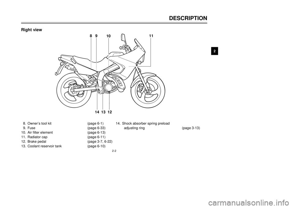
8. Owner’s tool kit (page 6-1)
9. Fuse (page 6-33)
10. Air filter element (page 6-13)
11. Radiator cap (page 6-11)
12. Brake pedal (page 3-7, 6-22)
13. Coolant reservoir tank (page 6-10)14. Shock absorber spring preload
adjusting ring (page 3-13)
89
1011
12
13 14
Right view
5AE-28199-E5 honbun 7/6/01 10:18 AM Page 9
Page 38 of 94

6-2
PERIODIC MAINTENANCE AND MINOR REPAIR
6
EAU03686
Periodic maintenance and lubrication chart
NOTE:
8
The annual checks must be performed every year, except if a kilometer-based maintenance is performed instead.
8From 30,000 km, repeat the maintenance intervals starting from 6,000 km.
8Items marked with an asterisk should be performed by a Yamaha dealer as they require special tools, data and
technical skills.NO. ITEM CHECK OR MAINTENANCE JOBODOMETER READING (× 1,000 km)
ANNUAL
CHECK
1 6 12 18 24
1
*Fuel line•Check fuel hoses for cracks or damage.√√√√ √
2 Spark plug•Replace.√√√√ √
3 Air filter element•Clean.√√
•Replace.√√
4 Clutch•Check operation.
•Adjust.√√√√√
5*Front brake•Check operation, fluid level and vehicle for fluid leakage.
(See NOTE on page 6-4.)√√√√√ √
•Replace brake pads.Whenever worn to the limit
6*Rear brake•Check operation, fluid level and vehicle for fluid leakage.
(See NOTE on page 6-4.)√√√√√ √
•Replace brake pads.Whenever worn to the limit
7*Brake hoses•Check for cracks or damage.√√√√ √
•Replace. (See NOTE on page 6-4.)Every 4 years
8*Wheels•Check runout and for damage.√√√√
5AE-28199-E5 honbun 7/6/01 10:18 AM Page 37
Page 40 of 94

6-4
PERIODIC MAINTENANCE AND MINOR REPAIR
6
EAU03884
NOTE:
8The air filter needs more frequent service if you are riding in unusually wet or dusty areas.
8Hydraulic brake service
9Regularly check and, if necessary, correct the brake fluid level.
9Every two years replace the internal components of the brake master cylinders and calipers, and change the
brake fluid.
9Replace the brake hoses every four years and if cracked or damaged.21 Transmission oil•Check oil level.√√√√√ √
•Change.√√
22
*Cooling system•Check coolant level and vehicle for coolant leakage.√√√√ √
•Change.Every 3 years
23*Front and rear brake
switches•Check operation.√√√√√ √
24 Moving parts and cables•Lubricate.√√√√ √
25*Lights, signals and
switches•Check operation.
•Adjust headlight beam.√√√√√ √ NO. ITEM CHECK OR MAINTENANCE JOBODOMETER READING (× 1,000 km)
ANNUAL
CHECK
1 6 12 18 24
5AE-28199-E5 honbun 7/6/01 10:18 AM Page 39
Page 49 of 94

6-13
PERIODIC MAINTENANCE AND MINOR REPAIR
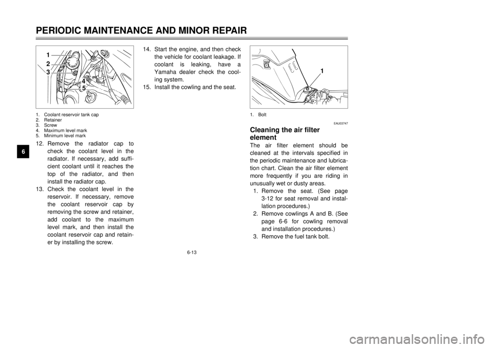
612. Remove the radiator cap to
check the coolant level in the
radiator. If necessary, add suffi-
cient coolant until it reaches the
top of the radiator, and then
install the radiator cap.
13. Check the coolant level in the
reservoir. If necessary, remove
the coolant reservoir cap by
removing the screw and retainer,
add coolant to the maximum
level mark, and then install the
coolant reservoir cap and retain-
er by installing the screw.14. Start the engine, and then check
the vehicle for coolant leakage. If
coolant is leaking, have a
Yamaha dealer check the cool-
ing system.
15. Install the cowling and the seat.
EAU03747
Cleaning the air filter
elementThe air filter element should be
cleaned at the intervals specified in
the periodic maintenance and lubrica-
tion chart. Clean the air filter element
more frequently if you are riding in
unusually wet or dusty areas.
1. Remove the seat. (See page
3-12 for seat removal and instal-
lation procedures.)
2. Remove cowlings A and B. (See
page 6-6 for cowling removal
and installation procedures.)
3. Remove the fuel tank bolt.
21
4
5
3
1
1. Coolant reservoir tank cap
2. Retainer
3. Screw
4. Maximum level mark
5. Minimum level mark1. Bolt
5AE-28199-E5 honbun 7/6/01 10:18 AM Page 48
Page 50 of 94

6-14
PERIODIC MAINTENANCE AND MINOR REPAIR
6 4. Lift the front of the fuel tank to
position the fuel tank away from
the air filter case. (Do not discon-
nect the fuel hoses!)
EW000071
w8Make sure that the fuel tank is
well supported.
8Do not tilt or pull the fuel tank
too much, otherwise the fuel
hoses may come loose, which
could cause fuel leakage.
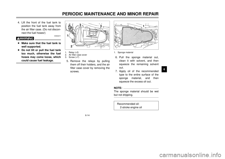
5. Remove the relays by pulling
them off their holders, and the air
filter case cover by removing the
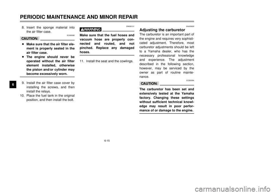
screws.6. Pull the sponge material out,
clean it with solvent, and then
squeeze the remaining solvent
out.
7. Apply oil of the recommended
type to the entire surface of the
sponge material, and then
squeeze the excess oil out.
NOTE:
The sponge material should be wet
but not dripping.
1
3
3
2
1
1. Relay (×2)
2. Air filter case cover
3. Screw (×7)1. Sponge material
Recommended oil:
2-stroke engine oil
5AE-28199-E5 honbun 7/6/01 10:18 AM Page 49
Page 51 of 94

6-15
PERIODIC MAINTENANCE AND MINOR REPAIR
68. Insert the sponge material into
the air filter case.
EC000082
cC8Make sure that the air filter ele-
ment is properly seated in the
air filter case.
8The engine should never be
operated without the air filter
element installed, otherwise
the piston and/or cylinder may
become excessively worn.9. Install the air filter case cover by
installing the screws, and then
install the relays.
10. Place the fuel tank in the original
position, and then install the bolt.
EW000131
wMake sure that the fuel hoses and
vacuum hose are properly con-
nected and routed, and not
pinched. Replace any damaged
hoses.11. Install the seat and the cowlings.
EAU00629
Adjusting the carburetorThe carburetor is an important part of
the engine and requires very sophisti-
cated adjustment. Therefore, most
carburetor adjustments should be left
to a Yamaha dealer, who has the
necessary professional knowledge
and experience. The adjustment
described in the following section,
however, may be serviced by the
owner as part of routine mainte-
nance.
EC000094
cCThe carburetor has been set and
extensively tested at the Yamaha
factory. Changing these settings
without sufficient technical knowl-
edge may result in poor perfor-
mance of or damage to the engine.
5AE-28199-E5 honbun 7/6/01 10:18 AM Page 50
Page 85 of 94

8-1
EAU01038
SPECIFICATIONS
8
Model TDR125
Dimensions
Overall length 2,120 mm
(F, GB, IRL, B, P, GR, E)
2,185 mm (S, SF, D, CH, A)
Overall width 840 mm
Overall height 1,295 mm
Seat height 850 mm
Wheel base 1,405 mm
Ground clearance 270 mm
Minimum turning radius 2,200 mm
Basic weight (with oil and full
fuel tank)135 kg
136 kg (CH, A)
Engine
Engine type Liquid cooled 2-stroke,
gasoline
Cylinder arrangement Forward inclined single
cylinder
Displacement 125 cm
3
Bore ×Stroke 56.0 ×50.7 mm
Compression ratio 6.6:1
Starting system Electric starter
Lubrication system Separate lubrication
(Yamaha Autolube)Engine oil (2-cycle)
Type Yamalube 2 or equivalent
2-stroke engine oil
Capacity
Total amount 1.2 L
Transmission oil
Type SAE 10W30 SE motor oil
Capacity
Periodic oil change 0.75 L
Total amount 0.8 L
Cooling system capacity
(total amount)1.05 L
Air filterWet type element
Fuel
Type REGULAR UNLEADED
GASOLINE ONLY
Fuel tank capacity 11 L
Reserve amount 2.2 L
Carburetor
Manufacturer MIKUNI
Model ×quantity TM28SS ×1
Specifications
5AE-28199-E5 honbun 7/6/01 10:18 AM Page 84