Page 55 of 1690
F42258
G24222
± BRAKEBRAKE FLUID
32±5
AVENSIS REPAIR MANUAL (RM1018E)
3. BLEED BRAKE LINE
(a) Connect the vinyl tube to the brake caliper.
(b) Depress the brake pedal several times, then loosen the
bleeder plug with the pedal depressed.
(c) At the point when the fluid stops, coming out tighten the
bleeder plug, then release the brake pedal.
(d) Repeat (b) and (c) until all the air in the fluid has been bled
out.
(e) Repeat the above procedure to bleed the air out of the
brake line for each wheel.
Torque: 10 N�m (102 kgf�cm, 7 ft.�lbf)
4. CHECK FLUID LEVEL IN RESERVOIR
(a) Check the fluid level and add fluid if necessary.
Fluid: SAE J1704 or FMVSS No. 116 DOT4
Page 67 of 1690
3201A±12
± BRAKEBRAKE SYSTEM
32±1
AVENSIS REPAIR MANUAL (RM1018E)
BRAKE SYSTEM
PRECAUTION
�Care must be taken to replace each part properly as it could affect the performance of the brake
system and result in a driving hazard. Replace the ones with parts having the same part number
or equivalent.
�It is very important to keep the parts and the area clean when repairing the brake system.
�If the vehicle is equipped with a mobile communication system, refer to the precaution in the
INTRODUCTION.
Page 183 of 1690

AVENSIS REPAIR MANUAL (RM1018E)
WATER PUMP ASSY(1CD±FTV)
REPLACEMENT
1.REMOVE RADIATOR SUPPORT OPENING COVER
2.REMOVE ENGINE ROOM CO")
160ME±01
A79148
SST
16±46
±
COOLING WATER PUMP ASSY(1CD±FTV)
AVENSIS REPAIR MANUAL (RM1018E)
WATER PUMP ASSY(1CD±FTV)
REPLACEMENT
1.REMOVE RADIATOR SUPPORT OPENING COVER
2.REMOVE ENGINE ROOM COVER SIDE
3.DRAIN ENGINE COOLANT(See page 16±44)
4.REMOVE FRONT WHEEL RH
5.REMOVE ENGINE UNDER COVER SUB±ASSY NO.1
6.REMOVE ENGINE UNDER COVER RH
7.REMOVE ENGINE COVER NO.1
(a)Remove the 5 nuts and the engine cover.
8.REMOVE INJECTOR DRIVER (See page 14±286)
9.REMOVE V (COOLER COMPRESSOR TO CRANKSHAFT PULLEY) BELT NO.1 (See page 14±269)
10.REMOVE GENERATOR V BELT (See page 14±269)
11.SEPARATE POWER STEERING IDLE PULLEY BRACKET (See page 14±286)
12.SEPARATE ENGINE MOUNTING INSULATOR SUB±ASSY RH(See page 14±307)
13.REMOVE CRANKSHAFT PULLEY(See page 14±307) SST 09213±54015 (90105±08076), 09330±00021, 09950±50013 (0995\
1±05010, 09952±05010, 09953±05020, 09954±05031)
14. REMOVE IDLER PULLEY SUB±ASSY
(a) Remove the bolt, the washer and the pulley.
15.REMOVE TIMING BELT NO.2 COVER(See page 14±307)
16.REMOVE TIMING BELT NO.1 COVER(See page 14±307)
17. REMOVE TIMING BELT GUIDE
18.REMOVE TRANSVERSE ENGINE ENGINE MOUNTING BRACKET(See page 14±307)
19.SET NO. 1 CYLINDER TO TDC/COMPRESSION(See page 14±307)
20.REMOVE TIMING CHAIN COVER PLATE(See page 14±307)
21.REMOVE TIMING BELT(See page 14±307)
22. REMOVE FUEL INLET PIPE SUB±ASSY(See page 11±69)
NOTICE:
After removing the fuel inlet pipe, cover the common rail
and injection pump with vinyl tape to prevent dust from be-
ing introduced.
(a) Remove the wire bracket and slide the engine wire.
(b) Using SST, remove the fuel inlet pipe from the common rail.
SST 09023±12700
(c) Using SST, remove the fuel inlet pipe from the injection pump.
SST 09023±12700
23.REMOVE INTAKE MANIFOLD INSULATOR NO.1(See page 11±69)
24. REMOVE OIL LEVEL GAGE SUB±ASSY
25.REMOVE OIL LEVEL GAGE GUIDE(See page 17±22)
26.REMOVE WATER INLET (See page 16±50)
27.DISCONNECT INJECTION PUMP TO FUEL PIPE FUEL HOSE(See page 11±69)
28.DISCONNECT INJECTION PUMP TO FUEL FILTER FUEL HOSE OR PIPE(See page 11±69)
Page 185 of 1690

AVENSIS REPAIR MANUAL (RM1018E)
39.INSTALL INTAKE MANIFOLD INSULATOR NO.1(See page 11±69) 40. INSTALL FUEL INLET PIPE SUB±ASSY
NOT")
A79148
SST
A79149
SST
16±48
±
COOLING WATER PUMP ASSY(1CD±FTV)
AVENSIS REPAIR MANUAL (RM1018E)
39.INSTALL INTAKE MANIFOLD INSULATOR NO.1(See page 11±69) 40. INSTALL FUEL INLET PIPE SUB±ASSY
NOTICE:
�In case of having the water pump replaced, must re-
place fuel inlet pipe, too.
�When assembling the pipe, perform the operation
with the engine cold under room temperature.
(a) Temporarily install the new fuel inlet pipe.
(b) Using SST, tighten the nut of the fuel inlet pipe to the com-
mon rail side.
SST 09023±12700
Torque:
42 N�m (428 kgf �cm, 31 ft �lbf) for a used pipe using SST
46 N �m (469 kgf �cm, 34 ft �lbf) for a used pipe not using
SST
31 N �m (316 kgf �cm, 23 ft �lbf) for a new pipe using SST
34 N �m (347 kgf �cm, 25 ft �lbf) for a new pipe not using
SST
HINT:
�Use a torque wrench with a fulcrum length of 30 cm
(11.81 in.)
�Check if the used pipe has deflection or is installed prop-
erly after inlet pipe is reassembled. If there is deflection
or if it can not be installed properly, replace the used pipe
with a new pipe.
(c) Using SST, tighten the nut of the fuel inlet pipe to the injec- tion pump side.
SST 09023±12700
Torque:
42 N�m (428 kgf �cm, 31 ft �lbf) for a used pipe using SST
46 N �m (469 kgf �cm, 34 ft �lbf) for a used pipe not using
SST
31 N �m (316 kgf �cm, 23 ft �lbf) for a new pipe using SST
34 N �m (347 kgf �cm, 25 ft �lbf) for a new pipe not using
SST
HINT:
�Use a torque wrench with a fulcrum length of 30 cm
(11.81 in.)
�Check if the used pipe has deflection or is installed prop-
erly after inlet pipe is reassembled. If there is deflection
or if it can not be installed properly, replace the used pipe
with a new pipe.
Page 191 of 1690

REPLACEMENT
HINT:
Replace the RH side by the same")
300JY±01
������F45751
SST
C80291
F44775
C67088
30±22
±
DRIVE SHAFT / PROPELLER SHAFT FRONT AXLE HUB SUB±ASSY LH
AVENSIS REPAIR MANUAL (RM1018E)
REPLACEMENT
HINT:
Replace the RH side by the same procedures as the LH side.
1. REMOVE FRONT WHEEL
2.SEPARATE FRONT STABILIZER LINK ASSY LH (See page 30±6) 3. REMOVE FRONT AXLE HUB LH NUT
(a) Using SST and a hammer, unstake the staked part of theaxle hub LH nut.
SST 09930±00010
(b) While applying the brakes, remove the axle hub LH nut.
4. DISCONNECT SPEED SENSOR FRONT LH
(a) Remove the bolt, and disconnect the speed sensor wire and flexible hose from the shock absorber.
(b) Remove the bolt, separate the speed sensor front LH from the steering knuckle.
NOTICE:
�Be careful not to damage the speed sensor.
�Prevent foreign matter from attaching to the speed
sensor.
5. SEPARATE FRONT DISC BRAKE CALIPER ASSY LH
(a) Removing the 2 bolts, separate the disc brake caliper assy LH from the steering knuckle.
NOTICE:
Use a string or other device to keep the brake caliper from
hanging down.
Page 196 of 1690

25. INSTALL FRONT DISC BRAKE CALIPER ASSY LH
(a) Install the disc brake calip")
C67088
F44775
C80291
±
DRIVE SHAFT / PROPELLER SHAFT FRONT AXLE HUB SUB±ASSY LH
30±27
AVENSIS REPAIR MANUAL (RM1018E)
25. INSTALL FRONT DISC BRAKE CALIPER ASSY LH
(a) Install the disc brake caliper assy with the 2 bolts to the
steering knuckle.
Torque: 104 N �m (1,040 kgf �cm, 75 ft �lbf)
26. INSTALL FRONT AXLE HUB LH NUT
(a) Using a socket wrench (30 mm), install a new axle hub LH nut. Torque: 216 N �m (2,200 kgf �cm, 159 ft �lbf)
27. SEPARATE FRONT DISC BRAKE CALIPER ASSY LH
(a) Removing the 2 bolts, separate the disc brake caliper assy from the stee\
ring knuckle.
NOTICE:
Use a string or other device to keep the brake caliper from hanging down\
.
28. REMOVE FRONT DISC
29.INSPECT BEARING BACKLASH (See page 30±2)
30.INSPECT AXLE HUB DEVIATION (See page 30±2)
31. INSTALL FRONT DISC
32. INSTALL FRONT DISC BRAKE CALIPER ASSY LH
(a) Install the disc brake caliper assy with the 2 bolts to the steering knu\
ckle. Torque: 104 N �m (1,040 kgf �cm, 75 ft �lbf)
33. CONNECT SPEED SENSOR FRONT LH
(a) Install the speed sensor front LH to the steering knuckle with the bolt.
Torque: 8.0 N �m (82 kgf �cm, 71 in. �lbf)
(b) Connect the speed sensor wire and flexible hose to the shock absorber with the bolt.
Torque: 19 N �m (194 kgf �cm, 14 ft �lbf)
NOTICE:
�Be careful not to damage the speed sensor.
�Keep the speed sensor clean.
�Do not twist the sensor wire when installing the sen-
sor.
Page 203 of 1690

REPLACEMENT
HINT:
Replace the RH side by the sam")
300JZ±01
������F45267
F44818
������F45752
SST
±
DRIVE SHAFT / PROPELLER SHAFT REAR AXLE CARRIER SUB±ASSY LH
30±31
AVENSIS REPAIR MANUAL (RM1018E)
REPLACEMENT
HINT:
Replace the RH side by the same procedures as the LH side.
1. INSPECT REAR AXLE CARRIER SUB±ASSY LH
(a) Check that there is no looseness on the ball joint by shaking the lower arm up and down with a force
of 294 N (30kgf, 66 lbf).
2. REMOVE REAR WHEEL
3. DISCONNECT SKID CONTROL SENSOR WIRE
(a) Remove the bolt, disconnect the skid control sensor wire.
(b) Disconnect the connector.
4. SEPARATE REAR DISC BRAKE CALIPER ASSY LH
(a) Removing the 2 bolts and rear disc brake caliper assy.
NOTICE:
Use a string or other device to keep the brake caliper from hanging down\
.
5. REMOVE REAR DISC
6.REMOVE PARKING BRAKE ADJUSTER KIT (See page 33±14)
7.REMOVE PARKING BRAKE SHOE ADJUSTING SCREW SET (See page 33±14)
8.REMOVE PARKING BRAKE SHOE KIT (See page 33±14) SST 09718±00010
9.REMOVE PARKING BRAKE SHOE LEVER LH (See page 33±14)
10. DISCONNECT PARKING BRAKE CABLE ASSY NO.3
(a) Using needle±nose pliers, and disconnect the parkingbrake cable assy No.3 from the backing plate.
11. SEPARATE LOWER CONTROL ARM ASSY LH
(a) Loosen the lower control arm assy bolt (member side).
(b) Remove the clip and nut.
(c) Using SST, separate the lower control arm assy from the axle carrier.
SST 09610±20012
Page 204 of 1690
������F45753HoldTurn
SST
G21537
G21542
G20965
30±32
± DRIVE SHAFT / PROPELLER SHAFTREAR AXLE CARRIER SUB±ASSY LH
AVENSIS REPAIR MANUAL (RM1018E)
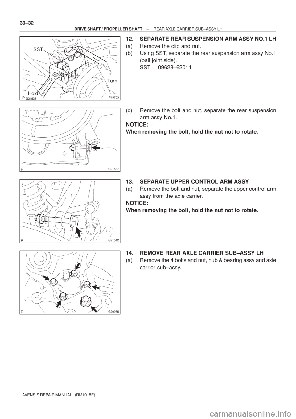
12. SEPARATE REAR SUSPENSION ARM ASSY NO.1 LH
(a) Remove the clip and nut.
(b) Using SST, separate the rear suspension arm assy No.1
(ball joint side).
SST 09628±62011
(c) Remove the bolt and nut, separate the rear suspension
arm assy No.1.
NOTICE:
When removing the bolt, hold the nut not to rotate.
13. SEPARATE UPPER CONTROL ARM ASSY
(a) Remove the bolt and nut, separate the upper control arm
assy from the axle carrier.
NOTICE:
When removing the bolt, hold the nut not to rotate.
14. REMOVE REAR AXLE CARRIER SUB±ASSY LH
(a) Remove the 4 bolts and nut, hub & bearing assy and axle
carrier sub±assy.

3. BLEED BRAKE LINE
(a) Connect the vinyl tube to the brake caliper.
(b) Depress the brake pedal several times, then loosen th")