Page 780 of 1690

SST (T joint)SST
SST
(Hose)
B12975
11±34
± FUELFUEL SYSTEM (1AZ±FSE)
AVENSIS REPAIR MANUAL (RM1018E)
(g) Install SST (pressure gauge) and a fuel tube")
No.1 Fuel Pipe
Fuel Tube Connector
SST
(Clip)
SST (T joint)SST
SST
(Hose)
B12975
11±34
± FUELFUEL SYSTEM (1AZ±FSE)
AVENSIS REPAIR MANUAL (RM1018E)
(g) Install SST (pressure gauge) and a fuel tube connector
using SST as shown in the illustration.
SST 09268±41047(95336±08070),09268±45014
(09268±41250, 09268±41200, 09268±41220)
(h) Wipe up any gasoline.
(i) Reconnect the negative (±) battery cable.
(j) Connect the hand±hand tester to the DLC3.
(k) Measure the fuel pressure.
Fuel pressure:
196 to 588 kPa (2 to 6 kgf/cm
2, 28 to 85 psi)
If pressure is high, replace the fuel pressure regulator.
If pressure is low, check the fuel hoses connections, the fuel
pump, the fuel filter and the fuel pressure regulator.
(l) Disconnect the hand±held tester from the DLC3.
(m) Start the engine.
(n) Measure the fuel pressure at idle.
Fuel pressure:
196 to 588 kPa (2 to 6 kgf/cm
2, 28 to 85 psi)
(o) Stop the engine.
(p) Check that the fuel pressure remains as specified for 5
minutes after the engine has stopped.
Fuel pressure:147 kPa (1.5 kgf/cm
2, 21 psi) or more
If pressure is not as specified, check the fuel pump, the pres-
sure regulator and/or the injectors.
(q) After checking the fuel pressure, disconnect the negative
(±) battery cable and carefully remove SST and the fuel
tube connector to prevent gasoline from splashing.
(r) Reconnect the No. 1 fuel pipe (fuel tube connector).
CAUTION:
After taking the precautions, connect the fuel tube con-
necter (quick type).
2. CHECK FUEL PUMP OPERATION AND CHECK FOR
FUEL LEAKS
(a) When using the hand±held tester
(1) Connect the hand±held tester to the DLC3.
(2) Turn the ignition switch ON and the hand±held tes-
ter main switch ON.
NOTICE:
Do not start the engine.
(3) Select the active test mode on the hand±held tester.
(4) Perform the active test. Check that the fuel pump
operates and check for fuel leaks.
Page 783 of 1690

11±31
AVENSIS REPAIR MANUAL (RM1018E)
(b) Observe the following precautions when removin")
A60083
Fuel Pipe
Clamp No.1
A
A
B12941
B12944
A82344
Vinyl Bag or plastic Bag
± FUELFUEL SYSTEM (1AZ±FSE)
11±31
AVENSIS REPAIR MANUAL (RM1018E)
(b) Observe the following precautions when removing and
installing fuel injectors.
NOTICE:
Never reuse the O±ring.
(1) When installing a new O±ring to the injector, be
careful not to damage the injector.
(2) Coat the new O±ring with grease or gasoline before
installing. Never use engine oil, gear oil or brake oil.
(c) Observe these following precautions when disconnecting
the fuel tube connector (quick type).
(1) Remove the fuel pipe clamp No.1.
(2) Check that there is no dirt or mud on the pipe and
around the connector before disconnecting them.
Clean them if necessary.
(3) Disconnect the connector from the hose while
pinching part A with fingers as shown in the illustra-
tion.
(4) When the connector and the pipe are stuck, push
and pull the connector to release and pull the con-
nector out from the pipe carefully.
(5) Inspect that there is no dirt or mud on the sealing
surface of the disconnected pipe. Clean it away if
necessary.
(6) To prevent the disconnected pipe and connector
from being damaged and foreign objects from being
introduced, cover them with a vinyl or plastic bag.
Page 807 of 1690
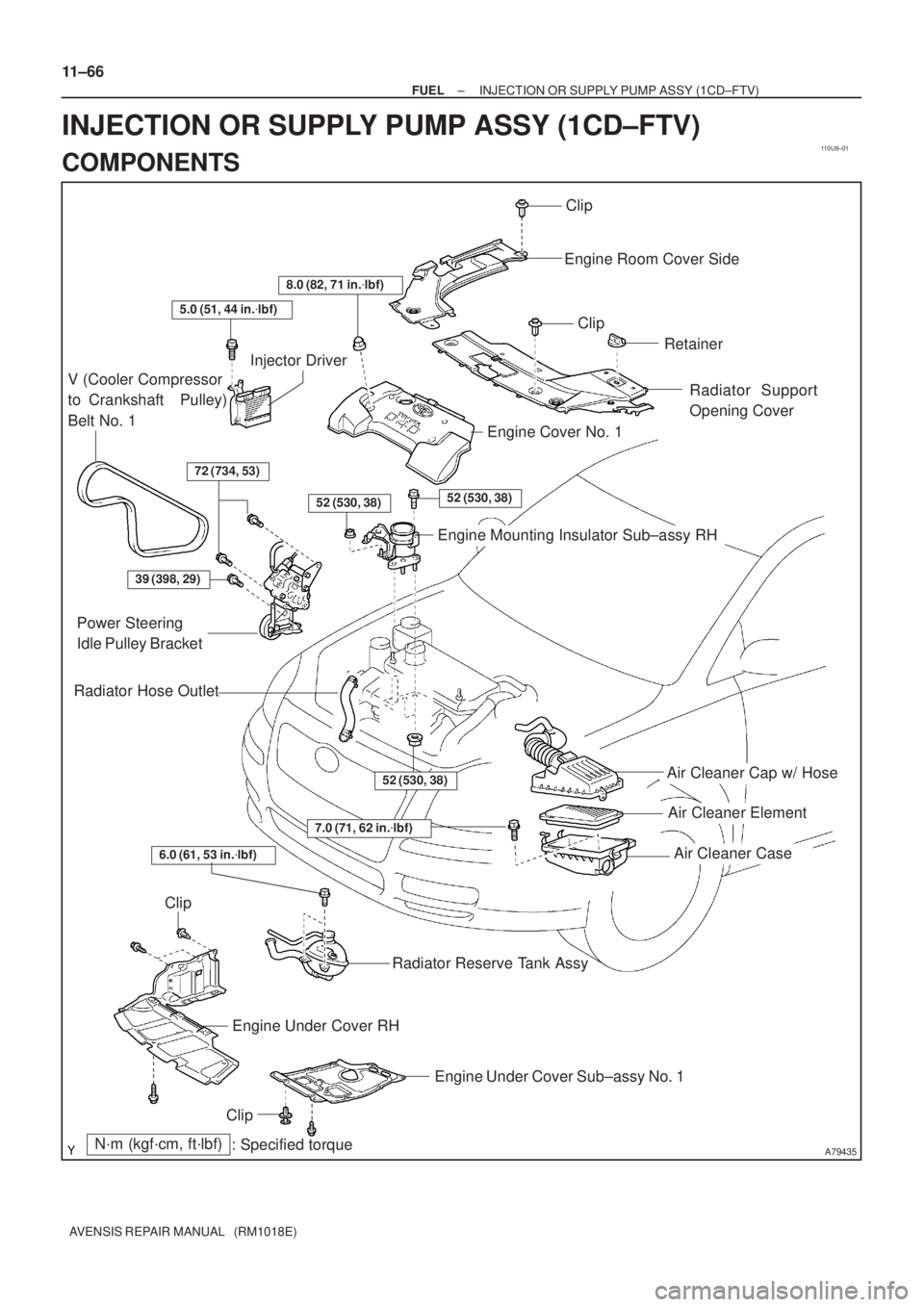
110U9±01
A79435
Air Cleaner Cap w/ Hose
Air Cleaner Element
Air Cleaner Case
7.0 (71, 62 in.�lbf)
N´m (kgf´cm, ft´lbf)
: Specified torque
Radiator Hose Outlet
Clip
Engine Room Cover Side
Clip
Retainer
Radiator Support
Opening Cover
8.0 (82, 71 in.�lbf)
5.0 (51, 44 in.�lbf)
V (Cooler Compressor
to Crankshaft Pulley)
Belt No. 1
Injector Driver
72 (734, 53)
52 (530, 38)52 (530, 38)
Engine Cover No. 1
Engine Mounting Insulator Sub±assy RH
39 (398, 29)
Power Steering
Idle Pulley Bracket
52 (530, 38)
Clip
Engine Under Cover RH
Engine Under Cover Sub±assy No. 1
Clip
Radiator Reserve Tank Assy
6.0 (61, 53 in.�lbf)
11±66
± FUELINJECTION OR SUPPLY PUMP ASSY (1CD±FTV)
AVENSIS REPAIR MANUAL (RM1018E)
INJECTION OR SUPPLY PUMP ASSY (1CD±FTV)
COMPONENTS
Page 810 of 1690

11±69
AVENSIS REPAIR MANUAL (RM1018E)
REPLACEMENT
1.REMOVE FRONT WHEEL RH
2.DRAIN ENGINE COOLANT(See page 16±44)
3.REMOVE ENGINE UN")
110UA±01
A15950
±
FUEL INJECTION OR SUPPLY PUMP ASSY(1CD±FTV)
11±69
AVENSIS REPAIR MANUAL (RM1018E)
REPLACEMENT
1.REMOVE FRONT WHEEL RH
2.DRAIN ENGINE COOLANT(See page 16±44)
3.REMOVE ENGINE UNDER COVER SUB±ASSY NO.1
4.REMOVE ENGINE UNDER COVER RH
5.REMOVE RADIATOR SUPPORT OPENING COVER
6.REMOVE ENGINE ROOM COVER SIDE
7.REMOVE AIR CLEANER ASSY (See page 11±60)
8.REMOVE ENGINE COVER NO.1
(a)Remove the 5 nuts and the engine cover.
9.REMOVE RADIATOR RESERVE TANK ASSY(See page 16±50)
10.DISCONNECT RADIATOR HOSE OUTLET
(a)Disconnect the radiator hose outlet from the water inlet.
11.REMOVE V (COOLER COMPRESSOR TO CRANKSHAFT PULLEY) BELT NO.1
(See page 14±269)
12.REMOVE GENERATOR V BELT (See page 14±269)
13.REMOVE INJECTOR DRIVER
(a)Remove the 2 nuts which are used to secure the injector driver.
(b)Disconnect the injector driver connector and the harness clamp.
(c)Remove the injector driver.
14.REMOVE ENGINE MOUNTING INSULATOR SUB±ASSY RH(See page 14±307)
15.REMOVE CRANKSHAFT PULLEY(See page 14±307)
SST09213±54015 (90105±08076), 09330±00021, 09950±50013 (0995\
1±05010, 09952±05010, 09953±05020, 09954±05031)
16.REMOVE IDLER PULLEY SUB±ASSY
(a)Remove the bolt and washer, then remove the idler pulley.
17.REMOVE TIMING BELT NO.2 COVER(See page 14±307)
18.REMOVE TIMING BELT NO.1 COVER(See page 14±307)
19. REMOVE TIMING BELT GUIDE
20. REMOVE TRANSVERSE ENGINE ENGINE MOUNTING BRACKET
(a) Remove the 6 bolts and the engine mounting bracket.
21.SET NO. 1 CYLINDER TO TDC/COMPRESSION(See page 14±307)
22.REMOVE TIMING CHAIN COVER PLATE(See page 14±307)
23.REMOVE TIMING BELT(See page 14±307)
Page 811 of 1690

AVENSIS REPAIR MANUAL (RM1018E)
24. REMOVE FUEL INLET PIPE SUB±ASSY
NOTICE:
After removing the fuel inlet pipe, cover th")
A79148
SST
A79143
SST
11±70
± FUELINJECTION OR SUPPLY PUMP ASSY (1CD±FTV)
AVENSIS REPAIR MANUAL (RM1018E)
24. REMOVE FUEL INLET PIPE SUB±ASSY
NOTICE:
After removing the fuel inlet pipe, cover the common rail
and injection pump with vinyl tape to prevent dust from be-
ing introduced.
(a) Remove the wire bracket and slide the engine wire.
(b) Using SST, remove the fuel inlet pipe from the common
rail.
SST 09023±12700
(c) Using SST, remove the fuel inlet pipe from the injection
pump.
SST 09023±12700
25. REMOVE INJECTION PIPE SUB±ASSY NO.1
(a) Remove the 2 nuts, then remove the 2 upper infection
pipe clamps from the intake manifold.
(b) Using SST, remove the injection pipe from the common
rail side.
SST 09023±12700
(c) Using SST, remove the injection pipe from the injector
side.
SST 09023±12700
(d) After removing the fuel pipe, to prevent dust or foreign ob-
jects from being introduced, cover the common rail with
vinyl tape and protect the injector inlet with a vinyl or a
plastic bag.
26. REMOVE INJECTION PIPE SUB±ASSY NO.2
SST 09023±12700
HINT:
Perform the same procedures as injection pipe No. 1.
27. REMOVE INJECTION PIPE SUB±ASSY NO.3
SST 09023±12700
HINT:
Perform the same procedures as injection pipe No. 1.
28. REMOVE INJECTION PIPE SUB±ASSY NO.4
SST 09023±12700
HINT:
Perform the same procedures as injection pipe No. 1.
Page 813 of 1690

AVENSIS REPAIR MANUAL (RM1018E)
(b)Using SST, remove the injection pump drive pulley. SST09950±50013 (09951±05010")
A62779SST
A79153
A62166
SST
11±72
±
FUEL INJECTION OR SUPPLY PUMP ASSY(1CD±FTV)
AVENSIS REPAIR MANUAL (RM1018E)
(b)Using SST, remove the injection pump drive pulley. SST09950±50013 (09951±05010, 09952±05010, 09953±05020, 09954±05021)
36.REMOVE INJECTION OR SUPPLY PUMP ASSY
(a)Remove the 2 nuts and the injection pump.
37.INSTALL INJECTION OR SUPPLY PUMP ASSY Torque: 21 N �m (210 kgf �cm, 15 ft �lbf)
38.INSTALL INJECTION PUMP DRIVE PULLEY
(a)Using SST, install the pulley nut. SST09960±10010 (09962±01000, 09963±01000)
Torque: 64 N �m (650 kgf �cm, 47 ft �lbf)
39.INSTALL WATER INLET(See page 16±50)
40.INSTALL OIL LEVEL GAGE GUIDE(See page 17±22)
41. INSTALL INTAKE MANIFOLD INSULATOR NO.1 Torque: 5.0 N �m (51 kgf �cm, 44 in. �lbf)
42. INSTALL INJECTION PIPE SUB±ASSY NO.1
NOTICE:
When assembling the pipes, perform the operation with the
engine cold under room temperature.
(a) Remove the vinyl or the plastic bag from the injector and vinyl tape from the common rail.
(b) Temporarily install the injection pipe.
Page 816 of 1690

11±75
AVENSIS REPAIR MANUAL (RM1018E)
52.INSTALL TIMING BELT GUIDE(See page 14±307)
53.INSTALL TIMING BELT NO.1 COVER(See page 14±307)
54.INSTALL")
±
FUEL INJECTION OR SUPPLY PUMP ASSY (1CD±FTV)
11±75
AVENSIS REPAIR MANUAL (RM1018E)
52.INSTALL TIMING BELT GUIDE(See page 14±307)
53.INSTALL TIMING BELT NO.1 COVER(See page 14±307)
54.INSTALL TIMING BELT NO.2 COVER(See page 14±307)
55. INSTALL IDLER PULLEY SUB±ASSY
Torque: 40 N �m (408 kgf �cm, 30 ft �lbf)
56.INSTALL CRANKSHAFT PULLEY(See page 14±307) SST 09213±54015 (90105±08076), 09330±00021
57.INSTALL ENGINE MOUNTING INSULATOR SUB±ASSY RH(See page 14±307)
58. INSTALL INJECTOR DRIVER Torque: 5.0 N �m (51 kgf �cm, 44 in. �lbf)
59. ADJUST V (COOLER COMPRESSOR TO CRANKSHAFT PULLEY) BELT NO.1 (See page 14±269)
60.INSTALL RADIATOR RESERVE TANK ASSY(See page 16±50)
61. INSTALL ENGINE COVER NO.1 Torque: 8.0 N �m (82 kgf �cm, 71 in. �lbf)
62.INSTALL AIR CLEANER ASSY (See page 11±60)
63. INSTALL FRONT WHEEL RH
Torque: 103 N �m (1,050 kgf �cm, 76 ft �lbf)
64.ADD ENGINE COOLANT(See page 16±44)
65.CHECK FOR ENGINE COOLANT LEAKS(See page 16±37)
66.CHECK FOR FUEL LEAKS(See page 11±60)
Page 817 of 1690
110U7±01
A79434
Radiator Support Opening Cover
Engine Cover No. 1
Vacuum Reservoir Sub±assy
Union To Connector Tube Hose
Air Cleaner Cap w/ Hose
Air Cleaner Element
Air Cleaner Case
N´m (kgf´cm, ft´lbf)
: Specified torque
8.0 (82, 71 in.�lbf)
8.3 (85, 73 in.�lbf)
7.0 (71, 62 in.�lbf)
Clip
Retainer
25 (255, 18)
Air Tube No. 1
25 (255, 18)
11±58
± FUELINJECTOR ASSY (1CD±FTV)
AVENSIS REPAIR MANUAL (RM1018E)
INJECTOR ASSY (1CD±FTV)
COMPONENTS