Page 741 of 1690

Insert
SST
Turn
Fuel Pipe
Clamp
A76220
O±ring
Nylon Tube HousingPipe
Retainer
A78472
±
FUEL FUEL INJECTOR ASSY(1ZZ±FE/3ZZ±FE)
11±11
AVENSIS REPAIR MANUAL")
110TZ±01
A78471
Retainer
(at 4 places)
Insert
SST
Turn
Fuel Pipe
Clamp
A76220
O±ring
Nylon Tube HousingPipe
Retainer
A78472
±
FUEL FUEL INJECTOR ASSY(1ZZ±FE/3ZZ±FE)
11±11
AVENSIS REPAIR MANUAL (RM1018E)
REPLACEMENT
1.DISCHARGE FUEL SYSTEM PRESSURE (See page 11±1)
2.REMOVE CYLINDER HEAD COVER NO.2 (See page 10±9)
3. SEPARATE FUEL TUBE SUB±ASSY
(a) Remove the fuel pipe clamp.
(b) Using SST, disconnect the fuel tube.SST 09268±21010
(1) Assemble SST to the connection of the fuel tube asshown in the illustration.
(2) Turn SST, align the retainers inside the connector
with SST into the connector.
(3) Push in the SST and the connector together to- wards the fuel tube assembly.
NOTICE:
�Check if there is any dirt or mud on the pipe and
around the connector before disconnecting them and
remove the dirt as necessary.
�Do not bent and twist the nylon tube.
�When the connector and pipe are stuck, push and pull
the connector to free. Pull the connector out carefully.
�Prevent the disconnected pipe and connector from
being damaged and foreign objects from being
introduced, cover with a vinyl or plastic bag.
4. REMOVE FUEL DELIVERY PIPE SUB±ASSY
(a) Disconnect the ventilation hose.
Page 742 of 1690
A78473
(a)(a)
(a)
(a)
(b)
(b)
(b)
A78480
A78475
Delivery Pipe No. 1 spacer
Insulator
A78476
11±12
± FUELFUEL INJECTOR ASSY (1ZZ±FE/3ZZ±FE)
AVENSIS REPAIR MANUAL (RM1018E)
(b) Disconnect the 4 fuel injector connectors.
(c) Remove the 3 wire harness clamps.
(d) Remove the 3 bolts, and then remove the fuel delivery
pipe together with the 4 fuel injectors.
NOTICE:
Be careful not to drop the fuel injectors when removing the
fuel delivery pipe.
(e) Remove the 2 delivery pipe No. 1 spacers and the 4 insu-
lators from the cylinder head.
5. REMOVE FUEL INJECTOR ASSY
(a) Pull out the 4 fuel injectors from the fuel delivery pipe.
Page 743 of 1690

11±13
AVENSIS REPAIR MANUAL (RM1018E)
6. INSTALL F")
A78477
New O±ring
1ZZ±FE:
A78478
New O±ring
3ZZ±FE:
New Grommet
A78479
Turn
Push
A78474
Turn
A
A
B
± FUELFUEL INJECTOR ASSY (1ZZ±FE/3ZZ±FE)
11±13
AVENSIS REPAIR MANUAL (RM1018E)
6. INSTALL FUEL INJECTOR ASSY
(a) Install new grommets to each fuel injector. (3ZZ±FE)
(b) Apply a light coat of spindle oil or gasoline to new O±rings,
and install them to each fuel injector.
(c) Apply a light coat of spindle oil or gasoline on the place
where the fuel delivery pipe contacts the O±ring.
(d) Push the fuel injector while twisting it back and forth to
install it to the fuel delivery pipe.
NOTICE:
�Be careful not to twist the O±ring.
�After installing the fuel injectors, check that they turn
smoothly. If not, reinstall it with a new O±ring.
7. INSTALL FUEL DELIVERY PIPE SUB±ASSY
(a) Instal 4 new insulators and the 2 delivery pipe No. 1
spacers to the cylinder head.
(b) Place the fuel delivery pipe and 4 fuel injectors together
to the cylinder head.
NOTICE:
Be careful not to drop the fuel injectors when installing the
fuel delivery pipe.
(c) Temporarily install 3 bolts which are used to secure the
fuel delivery pipe to the cylinder head.
(d) Check that the fuel injectors rotate smoothly.
If fuel injectors do not rotate smoothly, the probable cause is in-
correct installation of O±ring. Replace with the O±ring.
(e) Tighten the 3 bolts.
Torque:
19 N�m (194 kgf�cm, 14 ft�lbf) for bolt A
9.0 N�m (92 kgf�cm, 80 in.�lbf) for bolt B
(f) Install the 3 wire harness clamps.
(g) Connect the 4 fuel injector connectors.
(h) Connect the ventilation hose.
Page 744 of 1690
A81613
Fuel Pipe
Clamp
Push
11±14
±
FUEL FUEL INJECTOR ASSY(1ZZ±FE/3ZZ±FE)
AVENSIS REPAIR MANUAL (RM1018E)
8.CONNECT FUEL TUBE SUB±ASSY
(a)Push in the connector to the pipe until it makes ºclickº sound.
NOTICE:
�Check if there is any damage or foreign objects on the
connected part.
�After connecting, check if the connector and the pipe
are securely connected by pulling on them.
(b)Install the fuel pipe clamp.
9.CHECK FOR FUEL LEAKS (See page 11±5)
10.INSTALL CYLINDER HEAD COVER NO.2 (See page 10±9)
Page 748 of 1690
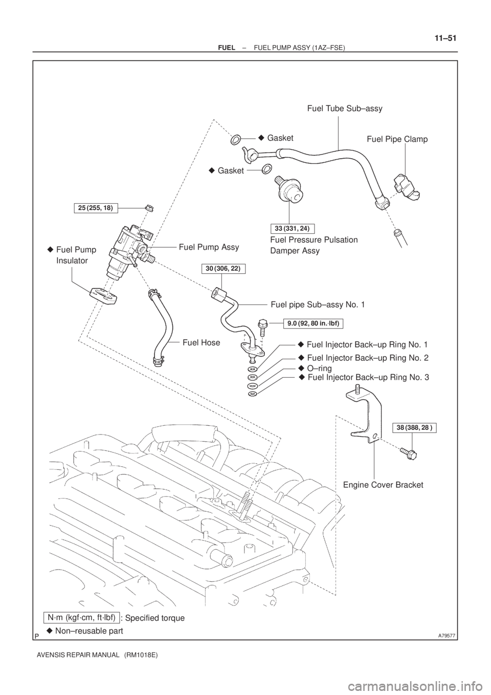
A79577
N´m (kgf´cm, ft´lbf)
: Specified torque
� Non±reusable part� Gasket� GasketFuel Tube Sub±assy
Fuel Pipe Clamp
Fuel Pressure Pulsation
Damper Assy Fuel Pump Assy
� Fuel Pump
Insulator
Fuel HoseFuel pipe Sub±assy No. 1
� Fuel Injector Back±up Ring No. 1
25 (255, 18)
33 (331, 24)
9.0 (92, 80 in.�lbf)
38 (388, 28 )
30 (306, 22)
� Fuel Injector Back±up Ring No. 2
� Fuel Injector Back±up Ring No. 3 � O±ring
Engine Cover Bracket
± FUELFUEL PUMP ASSY (1AZ±FSE)
11±51
AVENSIS REPAIR MANUAL (RM1018E)
Page 751 of 1690

AVENSIS REPAIR MANUAL")
A79575
Fuel Injector
Back±up Ring No. 1
Fuel Injector
Back±up Ring No. 2
O±ring
Fuel injector
Back±up Ring No. 3
A79576
A79570
SST
11±54
± FUELFUEL PUMP ASSY (1AZ±FSE)
AVENSIS REPAIR MANUAL (RM1018E)
10. INSTALL FUEL PIPE SUB±ASSY NO.1
(a) Attach a new O±ring, fuel injector back±up ring No. 1, No.
2 and No. 3 to the fuel pipe sub±assy No.1.
(b) Apply a small amount of fuel on the O±ring and install the
fuel pipe sub±assy No. 1 to the fuel pump assy and the
fuel delivery pipe sub±assy.
NOTICE:
Be careful not to damage both the sealing surfaces of the
fuel delivery pipe and the fuel pump when installing the fuel
pipe No.1.
(c) Tighten the nut by hand to attach the fuel pipe sub±assy
No. 1 to the fuel pump assy.
(d) In order to secure the fuel pipe sub±assy No. 1 to the fuel
delivery pipe sub±assy, tighten the 2 bolts to the specified
torque.
Torque: 9.0 N�m (92 kgf�cm, 80 in.�lbf)
(e) Clamp the union bolt on the fuel pump assy with a 21 mm
wrench and tighten the nut with the specified torque to se-
cure the fuel pipe sub±assy No. 1 to the fuel pump assy
using a 19 mm union±nut wrench.
Torque: 30 N�m (306 kgf�cm, 22 ft�lbf)
11. INSTALL FUEL PRESSURE PULSATION DAMPER
ASSY
(a) Install the fuel pulsation damper assy to the fuel pump
assy after fitting new 2 gaskets and fuel tube sub±assy
between those assys.
(b) Using SST, install the fuel pressure pulsation damper
assy to the fuel pump assy.
SST 09617±24011
Torque: 33 N�m (331 kgf�cm, 24 ft�lbf)
(c) Connect the fuel tube sub±assy.
Page 758 of 1690

B12947
SST (Hose)SST
(Clamp)
Vinyl Tube SST (Union)
O±Ring
A51875
11±22
±
FUEL FUEL SYSTEM(1AZ±FE)
AVENSIS REPAIR MANUAL (RM10")
110UY±01
Fuel Tube Connector
A50710
Fuel Tube Connector
SST
(Hose)
B12947
SST (Hose)SST
(Clamp)
Vinyl Tube SST (Union)
O±Ring
A51875
11±22
±
FUEL FUEL SYSTEM(1AZ±FE)
AVENSIS REPAIR MANUAL (RM1018E)
INSPECTION
1.INSPECT FUEL INJECTOR ASSY
(a)Inspect injector resistance (1)Using an ohmmeter, measure the resistance be-tween the terminals.
Resistance: 13.4 to 14.2 �at 20 �C (68 �F)
If the resistance is not as specified, replace the injector.
(b)Inspect injector inspection
CAUTION:
This test involves high±pressure fuel and electricity. Take
every precaution regarding safe handling of both the fuel
and the electricity. Preform this test in a safe area, and
avoid any sparks or flame. Do not smoke.
(1)Obtain new No. 1 fuel pipe (part No. 23901±0H040)and remove the fuel tube connector from the pipe.
(2)Install the fuel tube connector to SST (hose), then connect the tube connector and the fuel pipe.
SST09268±41047 (95336±08070)
CAUTION:
Connect the fuel tube connector (quick type) after observ-
ing the precautions to prevent fuel from spraying.
(3)Install the O±ring to the injector.
(4)Connect SST (union and hose) to the injector, andhold the injector and the union with SST (clamp)
SST09268±41047 (09268±41110, 09268±41300, 95336±08070)
(5)Put the injector into a graduated cylinder.
CAUTION:
Install a suitable vinyl tube onto the injector to contain gas-
oline spray. (6)Operate the fuel pump.(See Page 11±19)
Page 759 of 1690

11±23
AVENSIS REPAIR MANUAL (RM1018E)
(7) Connect SST (wire) to the injector and the battery
for 15 seconds, and measure the injection v")
SST
A50700
B00069
A16628A32859
± FUELFUEL SYSTEM (1AZ±FE)
11±23
AVENSIS REPAIR MANUAL (RM1018E)
(7) Connect SST (wire) to the injector and the battery
for 15 seconds, and measure the injection volume
with a graduated cylinder. Test each injector 2 or 3
times.
SST 09842±30080
Injection volume:
Injection volumeDifference between each injector
60 to 73 cm3
(3.6 to 4.5 cu in.)
in 15 seconds13 cm3 (0.9 cu in.) or less
NOTICE:
Always do the switching at the battery side.
If the injection volume is not as specified, replace the injector.
(c) Inspect leakage
(1) In the condition above, disconnect the test probes
of SST (wire) from the battery and check the fuel
leakage from the injector.
Fuel drop: 1 drop or less in 12 minutes
2. INSPECT FUEL PUMP
(a) Insect fuel pump resistance.
(1) Using an ohmmeter, measure the resistance be-
tween the terminals.
Resistance: 0.2 to 3.0 � at 20�C (68�F)
(b) Inspect fuel pump operation
(1) Apply battery voltage to both the terminals. Check
that the pump operates.
NOTICE:
�These tests must be done quickly (within 10 seconds)
to prevent damage to the pump.
�Keep fuel pump as far away from the battery as pos-
sible.
�Always do the switching at the battery side.
(a)
(a)
(a)
(b)
(b)
(b)
A78480
A78475
Delivery Pipe No. 1 spacer
Insulator
A78476
11±12
± FUELFUEL INJECTOR ASSY (1ZZ±FE/3ZZ±FE)
AVENSIS REPAIR MANUAL (RM1018E)
(b) Disconnect the 4 f")

AVENSIS REPAIR MANUAL (RM1018E)
8.CONNECT FUEL TUBE SUB±ASSY
(a)Push in the connector to the pipe until it makes ºcl")