Page 180 of 1690
A57664
Seal Width
2.2 to 2.5 mm0.5 to 1.0 mm
B12052
B12054
SST
16±22
±
COOLING WATER PUMP ASSY(1AZ±FE)
AVENSIS REPAIR MANUAL (RM1018E)
9.INSTALL WATER PUMP ASSY
(a)Remove any old packing (FIPG) material from the con- tact surface.
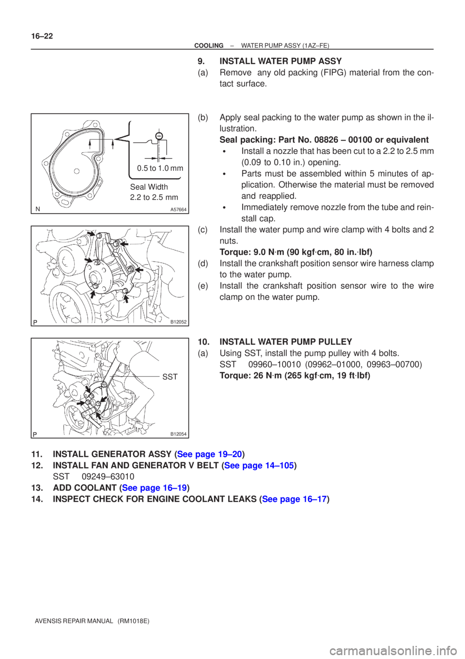
(b)Apply seal packing to the water pump as shown in the il- lustration.
Seal packing: Part No. 08826 ± 00100 or equivalent
�Install a nozzle that has been cut to a 2.2 to 2.5 mm
(0.09 to 0.10 in.) opening.
�Parts must be assembled within 5 minutes of ap-
plication. Otherwise the material must be removed
and reapplied.
�Immediately remove nozzle from the tube and rein-
stall cap.
(c)Install the water pump and wire clamp with 4 bolts and 2
nuts.
Torque: 9.0 N �m (90 kgf �cm, 80 in. �lbf)
(d)Install the crankshaft position sensor wire harness clamp to the water pump.
(e)Install the crankshaft position sensor wire to the wire clamp on the water pump.
10.INSTALL WATER PUMP PULLEY
(a)Using SST, install the pump pulley with 4 bolts. SST09960±10010 (09962±01000, 09963±00700)
Torque: 26 N �m (265 kgf �cm, 19 ft �lbf)
11.INSTALL GENERATOR ASSY (See page 19±20)
12.INSTALL FAN AND GENERATOR V BELT (See page 14±105) SST 09249±63010
13.ADD COOLANT (See page 16±19)
14.INSPECT CHECK FOR ENGINE COOLANT LEAKS (See page 16±17)
Page 181 of 1690
160MR±01
B12054
SST
B12052
B12053
Pry
PryPry
±
COOLING WATER PUMP ASSY(1AZ±FSE)
16±33
AVENSIS REPAIR MANUAL (RM1018E)
WATER PUMP ASSY(1AZ±FSE)
REPLACEMENT
1.DRAIN COOLANT (See page 16±31)
2. REMOVE RADIATOR SUPPORT OPENING COVER
3. REMOVE ENGINE ROOM COVER SIDE
4. REMOVE ENGINE UNDER COVER RH
5.REMOVE FAN AND GENERATOR V BELT (See page 14±185)
SST 09249±63010
6.REMOVE GENERATOR ASSY (See page 19±20)
7. REMOVE WATER PUMP PULLEY
(a) Using SST, remove 4 bolts and pump pulley.SST 09960±10010 (09962±01000, 09963±00700)
(b) Disconnect the crankshaft position sensor wire clamp from the water pump.
(c) Disconnect the crankshaft position sensor wire from the clamp on the water pump.
8. REMOVE WATER PUMP ASSY
(a) Remove 4 bolts, 2 nuts, wire clamp and water pump.
(b) Using a screwdriver, pry between the water pump and cyl- inder block, and remove the water pump.
NOTICE:
Be careful not to damage the contact surface of the water
pump and cylinder block.
Page 182 of 1690
A57664
Seal Width
2.2 to 2.5 mm0.5 to 1.0 mm
B12052
B12054
SST
16±34
±
COOLING WATER PUMP ASSY(1AZ±FSE)
AVENSIS REPAIR MANUAL (RM1018E)
9.INSTALL WATER PUMP ASSY
(a)Remove any old packing (FIPG) material from the contact surface.
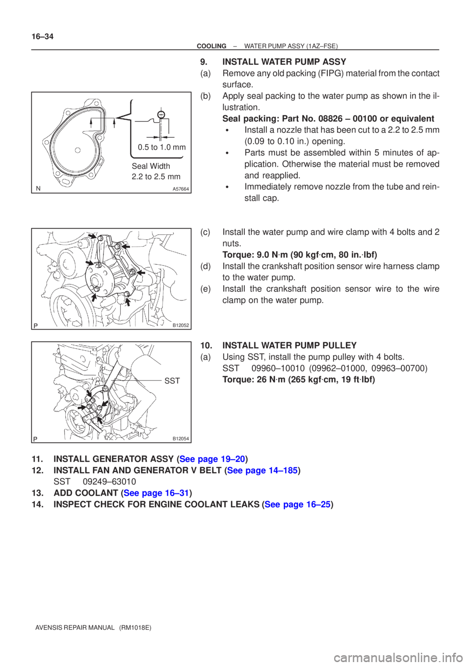
(b)Apply seal packing to the water pump as shown in the il- lustration.
Seal packing: Part No. 08826 ± 00100 or equivalent
�Install a nozzle that has been cut to a 2.2 to 2.5 mm
(0.09 to 0.10 in.) opening.
�Parts must be assembled within 5 minutes of ap-
plication. Otherwise the material must be removed
and reapplied.
�Immediately remove nozzle from the tube and rein-
stall cap.
(c)Install the water pump and wire clamp with 4 bolts and 2 nuts.
Torque: 9.0 N �m (90 kgf �cm, 80 in. �lbf)
(d)Install the crankshaft position sensor wire harness clamp to the water pump.
(e)Install the crankshaft position sensor wire to the wire clamp on the water pump.
10.INSTALL WATER PUMP PULLEY
(a)Using SST, install the pump pulley with 4 bolts. SST09960±10010 (09962±01000, 09963±00700)
Torque: 26 N �m (265 kgf �cm, 19 ft �lbf)
11.INSTALL GENERATOR ASSY (See page 19±20)
12.INSTALL FAN AND GENERATOR V BELT (See page 14±185) SST 09249±63010
13.ADD COOLANT (See page 16±31)
14.INSPECT CHECK FOR ENGINE COOLANT LEAKS(See page 16±25)
Page 183 of 1690
160ME±01
A79148
SST
16±46
±
COOLING WATER PUMP ASSY(1CD±FTV)
AVENSIS REPAIR MANUAL (RM1018E)
WATER PUMP ASSY(1CD±FTV)
REPLACEMENT
1.REMOVE RADIATOR SUPPORT OPENING COVER
2.REMOVE ENGINE ROOM COVER SIDE
3.DRAIN ENGINE COOLANT(See page 16±44)
4.REMOVE FRONT WHEEL RH
5.REMOVE ENGINE UNDER COVER SUB±ASSY NO.1
6.REMOVE ENGINE UNDER COVER RH
7.REMOVE ENGINE COVER NO.1
(a)Remove the 5 nuts and the engine cover.
8.REMOVE INJECTOR DRIVER (See page 14±286)
9.REMOVE V (COOLER COMPRESSOR TO CRANKSHAFT PULLEY) BELT NO.1 (See page 14±269)
10.REMOVE GENERATOR V BELT (See page 14±269)
11.SEPARATE POWER STEERING IDLE PULLEY BRACKET (See page 14±286)
12.SEPARATE ENGINE MOUNTING INSULATOR SUB±ASSY RH(See page 14±307)
13.REMOVE CRANKSHAFT PULLEY(See page 14±307) SST 09213±54015 (90105±08076), 09330±00021, 09950±50013 (0995\
1±05010, 09952±05010, 09953±05020, 09954±05031)
14. REMOVE IDLER PULLEY SUB±ASSY
(a) Remove the bolt, the washer and the pulley.
15.REMOVE TIMING BELT NO.2 COVER(See page 14±307)
16.REMOVE TIMING BELT NO.1 COVER(See page 14±307)
17. REMOVE TIMING BELT GUIDE
18.REMOVE TRANSVERSE ENGINE ENGINE MOUNTING BRACKET(See page 14±307)
19.SET NO. 1 CYLINDER TO TDC/COMPRESSION(See page 14±307)
20.REMOVE TIMING CHAIN COVER PLATE(See page 14±307)
21.REMOVE TIMING BELT(See page 14±307)
22. REMOVE FUEL INLET PIPE SUB±ASSY(See page 11±69)
NOTICE:
After removing the fuel inlet pipe, cover the common rail
and injection pump with vinyl tape to prevent dust from be-
ing introduced.
(a) Remove the wire bracket and slide the engine wire.
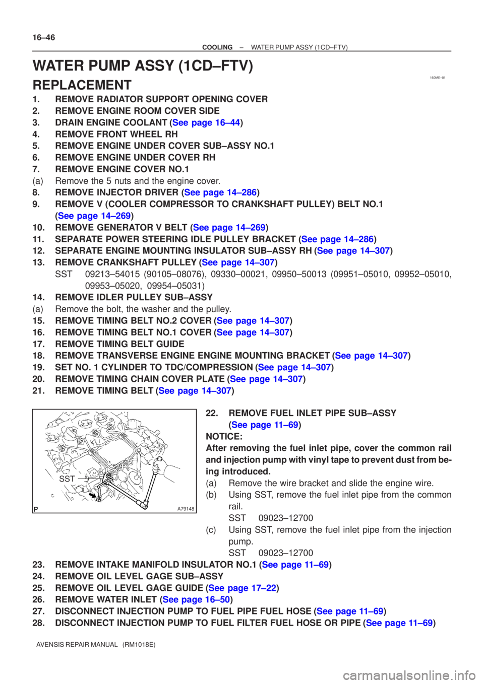
(b) Using SST, remove the fuel inlet pipe from the common rail.
SST 09023±12700
(c) Using SST, remove the fuel inlet pipe from the injection pump.
SST 09023±12700
23.REMOVE INTAKE MANIFOLD INSULATOR NO.1(See page 11±69)
24. REMOVE OIL LEVEL GAGE SUB±ASSY
25.REMOVE OIL LEVEL GAGE GUIDE(See page 17±22)
26.REMOVE WATER INLET (See page 16±50)
27.DISCONNECT INJECTION PUMP TO FUEL PIPE FUEL HOSE(See page 11±69)
28.DISCONNECT INJECTION PUMP TO FUEL FILTER FUEL HOSE OR PIPE(See page 11±69)
Page 186 of 1690
±
COOLING WATER PUMP ASSY(1CD±FTV)
16±49
AVENSIS REPAIR MANUAL (RM1018E)
41.SET NO. 1 CYLINDER TO TDC/COMPRESSION
SST09960±10010 (09962±01000, 09963±01000)
42.INSTALL TIMING BELT(See page 14±307)
43.CHECK VALVE TIMING(See page 14±307)
44.INSTALL TIMING CHAIN COVER PLATE(See page 14±307)
45.INSTALL TRANSVERSE ENGINE ENGINE MOUNTING BRACKET(See page 14±307)
46.INSTALL TIMING BELT GUIDE(See page 14±307)
47.INSTALL TIMING BELT NO.1 COVER(See page 14±307)
48.INSTALL TIMING BELT NO.2 COVER(See page 14±307)
49.INSTALL IDLER PULLEY SUB±ASSY(See page 11±69)
50.INSTALL CRANKSHAFT PULLEY(See page 14±307) SST 09213±54015 (90105±08076), 09330±00021
51.INSTALL ENGINE MOUNTING INSULATOR SUB±ASSY RH(See page 14±307)
52.INSTALL POWER STEERING IDLE PULLEY BRACKET (See page 14±286)
53.ADJUST V (COOLER COMPRESSOR TO CRANKSHAFT PULLEY) BELT NO.1 (See page 14±269)
54.INSTALL INJECTOR DRIVER(See page 11±69)
55. INSTALL FRONT WHEEL RH Torque: 103 N �m (1,050 kgf �cm, 76 ft �lbf)
56. INSTALL ENGINE COVER NO.1
Torque: 8.0 N �m (82 kgf �cm, 71 in. �lbf)
57.ADD ENGINE COOLANT(See page 16±44)
58.CHECK FOR ENGINE COOLANT LEAKS(See page 16±44)
59.CHECK FOR FUEL LEAKS(See page 11±60)
Page 187 of 1690
160MI±01
B00150
AB ABB
B
A32555
±
COOLING WATER PUMP ASSY(1ZZ±FE/3ZZ±FE)
16±9
AVENSIS REPAIR MANUAL (RM1018E)
WATER PUMP ASSY(1ZZ±FE/3ZZ±FE)
REPLACEMENT
1.REMOVE RADIATOR SUPPORT OPENING COVER (See page 14±27)
2.REMOVE ENGINE ROOM COVER SIDE (See page 14±27)
3.REMOVE ENGINE UNDER COVER SUB±ASSY NO.1 (See page 14±27)
4.REMOVE ENGINE UNDER COVER RH (See page 14±27)
5.DRAIN ENGINE COOLANT (See page 16±1)
6.REMOVE FAN AND GENERATOR V BELT (See page 14±5)
7.REMOVE GENERATOR ASSY (See page 19±7)
8.REMOVE WATER PUMP ASSY
(a)Remove the 6 bolts, the water pump and the O±ring.
9.INSTALL WATER PUMP ASSY
(a)Place a new O±ring on the timing chain cover.
(b)Install the water pump with the 6 bolts.Torque:
9.0 N�m (92 kgf �cm, 80 in �lbf) for Bolt A
11 N �m (113 kgf �cm, 8 ft �lbf) for Bolt B
10.INSTALL GENERATOR ASSY (See page 19±7)
11.ADD ENGINE COOLANT (See page 16±7)
12.CHECK FOR ENGINE COOLANT LEAKS (See page 16±1)
Page 211 of 1690
1209I±02
± EMISSION CONTROLEGR SYSTEM (1CD±FTV)
12±17
AVENSIS REPAIR MANUAL (RM1018E)
EGR SYSTEM (1CD±FTV)
ON±VEHICLE INSPECTION
HINT:
In a malfunction where the EGR system is always on, black smoke or white smoke may be emitted from the
exhaust pipe. If this occurs, inspect the EGR system as well.
1. INSPECT SEATING OF EGR VALVE
(a) Start the engine and check that it starts and runs at idle.
2. INSPECT HOT ENGINE CONDITION (WHEN USING HAND±HELD TESTER)
(a) Connect the hand±held tester to the DLC3.
(b) Start the engine and run it at idle.
(c) Select the ACTIVE TEST mode on the hand±held tester.
HINT:
Refer to the hand±held tester operator's manual for further details.
(d) Warm up the engine, the coolant temperature should be above 75�C (109�F) and bellow 90�C
(194�F).
(e) Check that the AFM reading is 5�ega�8 g/s with the engine idling.
(f) Operate the EGR valve with a hand±held tester. Regulate the valve opening angle to 0, and check that
the AFM reading is 11�ega�17 g/s..
If the AFM reading is out of range in either (e) or (f), replace the EGR valve.
If the AFM is out of range in both (e) and (f), replace the air flow meter (air cleaner) and check the EGR valve
operation again.
3. INSPECT HOT ENGINE CONDITION (WHEN NOT USING HAND±HELD TESTER)
(a) Install the vacuum gauge.
(1) Using a 3±way connector, connect a vacuum gauge to the hose between the intake manifold and
the turbo pressure sensor.
(b) Warm up the engine, the coolant temperature should be above 75�C (109�F) and bellow 90�C
(194�F).
(c) Check that the vacuum gauge indicates about more than 2.5 kPa (19 mmHg 0.7 in Hg).
(d) Stop the engine (IG OFF), remove the EGR valve connector, restart the engine, and check that load
under idling is less than 2.5 kPa (19 mmHg 0.7 in Hg).
If the load pressure exceeds the above value, replace the EGR valve.
Page 232 of 1690
������������
30
20
10
5
3
02040 0.11
0.3
0.2 0.52
60 80 100 ±20
(±4) (104) (140) (176)(32) (68) (212)
Z17274
Ohmmeter
Acceptable
Temperature �C (�F)
Resistance k�
THF E2
A30331
30
20
10
�
�
�
�
0.5
0.3
0.2
0.1
±20�
20 4060
80 100
F14741(±4) (104) (140) (176)(32) (68) (212)
A56276
Temperature �C (�F)
Resistance k�
± ENGINE CONTROL SYSTEMECD SYSTEM (1CD±FTV)
10±57
AVENSIS REPAIR MANUAL (RM1018E)
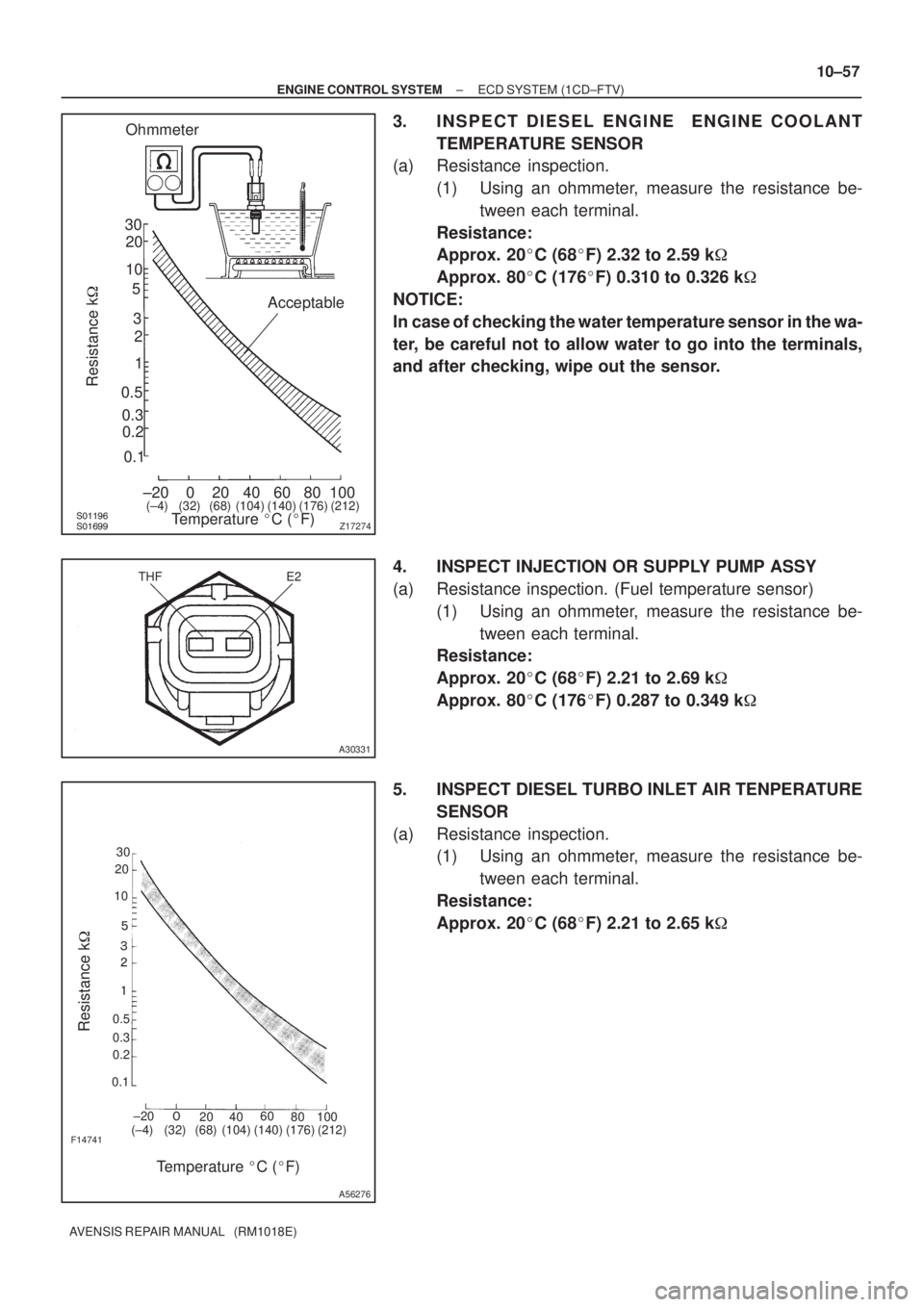
3. INSPECT DIESEL ENGINE ENGINE COOLANT
TEMPERATURE SENSOR
(a) Resistance inspection.
(1) Using an ohmmeter, measure the resistance be-
tween each terminal.
Resistance:
Approx. 20�C (68�F) 2.32 to 2.59 k�
Approx. 80�C (176�F) 0.310 to 0.326 k�
NOTICE:
In case of checking the water temperature sensor in the wa-
ter, be careful not to allow water to go into the terminals,
and after checking, wipe out the sensor.
4. INSPECT INJECTION OR SUPPLY PUMP ASSY
(a) Resistance inspection. (Fuel temperature sensor)
(1) Using an ohmmeter, measure the resistance be-
tween each terminal.
Resistance:
Approx. 20�C (68�F) 2.21 to 2.69 k�
Approx. 80�C (176�F) 0.287 to 0.349 k�
5. INSPECT DIESEL TURBO INLET AIR TENPERATURE
SENSOR
(a) Resistance inspection.
(1) Using an ohmmeter, measure the resistance be-
tween each terminal.
Resistance:
Approx. 20�C (68�F) 2.21 to 2.65 k�