Page 552 of 1690
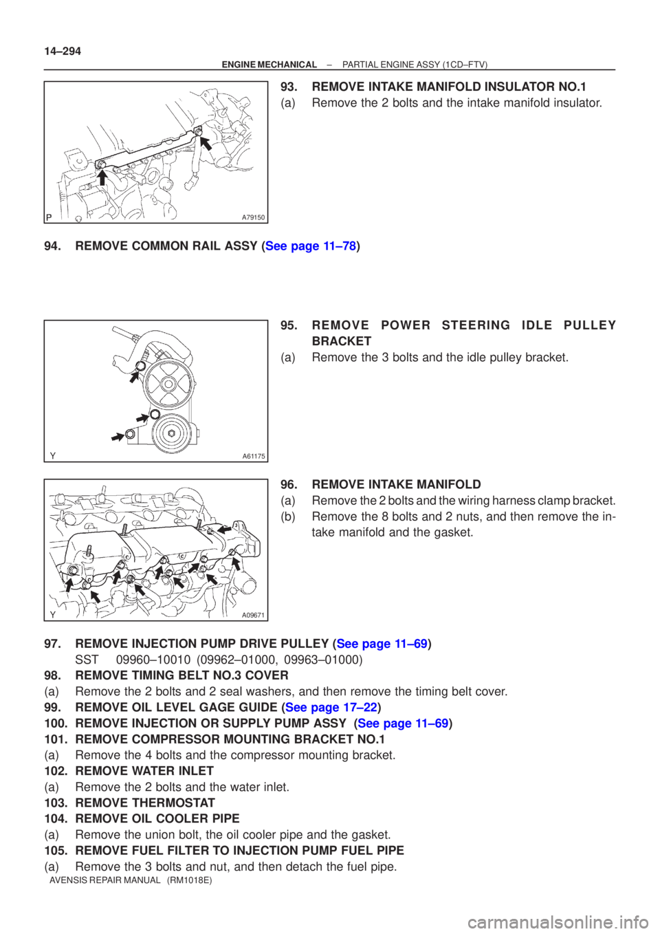
A79150
A61175
A09671
14±294
±
ENGINE MECHANICAL PARTIAL ENGINE ASSY(1CD±FTV)
AVENSIS REPAIR MANUAL (RM1018E)
93.REMOVE INTAKE MANIFOLD INSULATOR NO.1
(a)Remove the 2 bolts and the intake manifold insulator.
94.REMOVE COMMON RAIL ASSY (See page 11±78) 95.REMOVE POWER STEERING IDLE PULLEY
BRACKET
(a)Remove the 3 bolts and the idle pulley bracket.
96.REMOVE INTAKE MANIFOLD
(a)Remove the 2 bolts and the wiring harness clamp bracket.
(b)Remove the 8 bolts and 2 nuts, and then remove the in- take manifold and the gasket.
97.REMOVE INJECTION PUMP DRIVE PULLEY (See page 11±69) SST 09960±10010 (09962±01000, 09963±01000)
98. REMOVE TIMING BELT NO.3 COVER
(a) Remove the 2 bolts and 2 seal washers, and then remove the timing belt c\
over.
99.REMOVE OIL LEVEL GAGE GUIDE (See page 17±22)
100.REMOVE INJECTION OR SUPPLY PUMP ASSY (See page 11±69)
101. REMOVE COMPRESSOR MOUNTING BRACKET NO.1
(a) Remove the 4 bolts and the compressor mounting bracket.
102. REMOVE WATER INLET
(a) Remove the 2 bolts and the water inlet.
103. REMOVE THERMOSTAT
104. REMOVE OIL COOLER PIPE
(a) Remove the union bolt, the oil cooler pipe and the gasket.
105. REMOVE FUEL FILTER TO INJECTION PUMP FUEL PIPE
(a) Remove the 3 bolts and nut, and then detach the fuel pipe.
Page 556 of 1690
A79149
Fulcrum
Length
30 cm
SST
A81587
14±298
± ENGINE MECHANICALPARTIAL ENGINE ASSY (1CD±FTV)
AVENSIS REPAIR MANUAL (RM1018E)
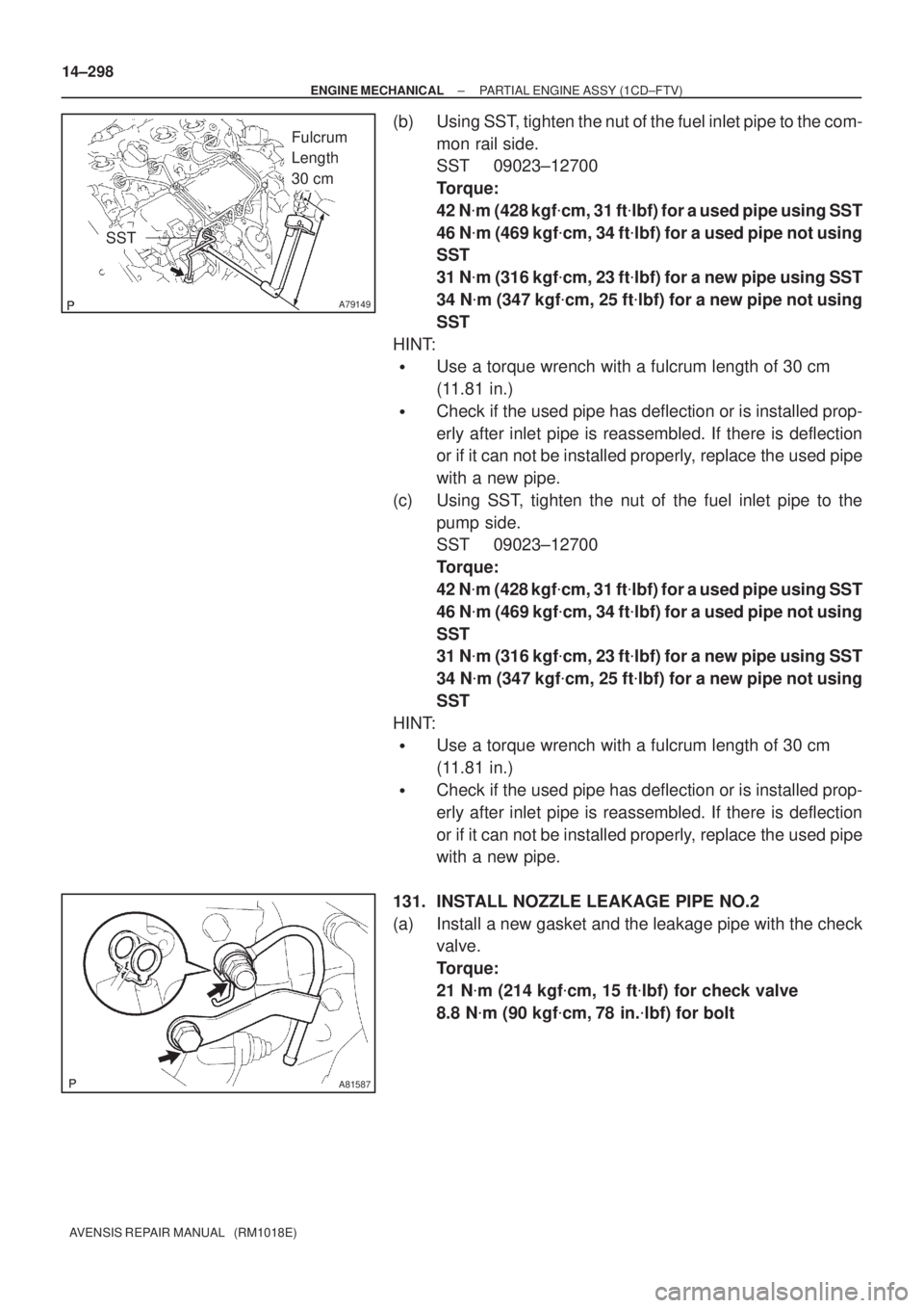
(b) Using SST, tighten the nut of the fuel inlet pipe to the com-
mon rail side.
SST 09023±12700
Torque:
42 N�m (428 kgf�cm, 31 ft�lbf) for a used pipe using SST
46 N�m (469 kgf�cm, 34 ft�lbf) for a used pipe not using
SST
31 N�m (316 kgf�cm, 23 ft�lbf) for a new pipe using SST
34 N�m (347 kgf�cm, 25 ft�lbf) for a new pipe not using
SST
HINT:
�Use a torque wrench with a fulcrum length of 30 cm
(11.81 in.)
�Check if the used pipe has deflection or is installed prop-
erly after inlet pipe is reassembled. If there is deflection
or if it can not be installed properly, replace the used pipe
with a new pipe.
(c) Using SST, tighten the nut of the fuel inlet pipe to the
pump side.
SST 09023±12700
Torque:
42 N�m (428 kgf�cm, 31 ft�lbf) for a used pipe using SST
46 N�m (469 kgf�cm, 34 ft�lbf) for a used pipe not using
SST
31 N�m (316 kgf�cm, 23 ft�lbf) for a new pipe using SST
34 N�m (347 kgf�cm, 25 ft�lbf) for a new pipe not using
SST
HINT:
�Use a torque wrench with a fulcrum length of 30 cm
(11.81 in.)
�Check if the used pipe has deflection or is installed prop-
erly after inlet pipe is reassembled. If there is deflection
or if it can not be installed properly, replace the used pipe
with a new pipe.
131. INSTALL NOZZLE LEAKAGE PIPE NO.2
(a) Install a new gasket and the leakage pipe with the check
valve.
Torque:
21 N�m (214 kgf�cm, 15 ft�lbf) for check valve
8.8 N�m (90 kgf�cm, 78 in.�lbf) for bolt
Page 722 of 1690
110UB±01
A79437
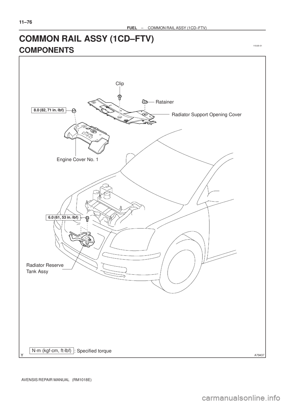
8.0 (82, 71 in.�lbf)
Engine Cover No. 1Radiator Support Opening Cover
N´m (kgf´cm, ft´lbf)
: Specified torque
6.0 (61, 53 in.�lbf)
Radiator Reserve
Tank Assy
Clip
Ratainer
11±76
± FUELCOMMON RAIL ASSY (1CD±FTV)
AVENSIS REPAIR MANUAL (RM1018E)
COMMON RAIL ASSY (1CD±FTV)
COMPONENTS
Page 723 of 1690
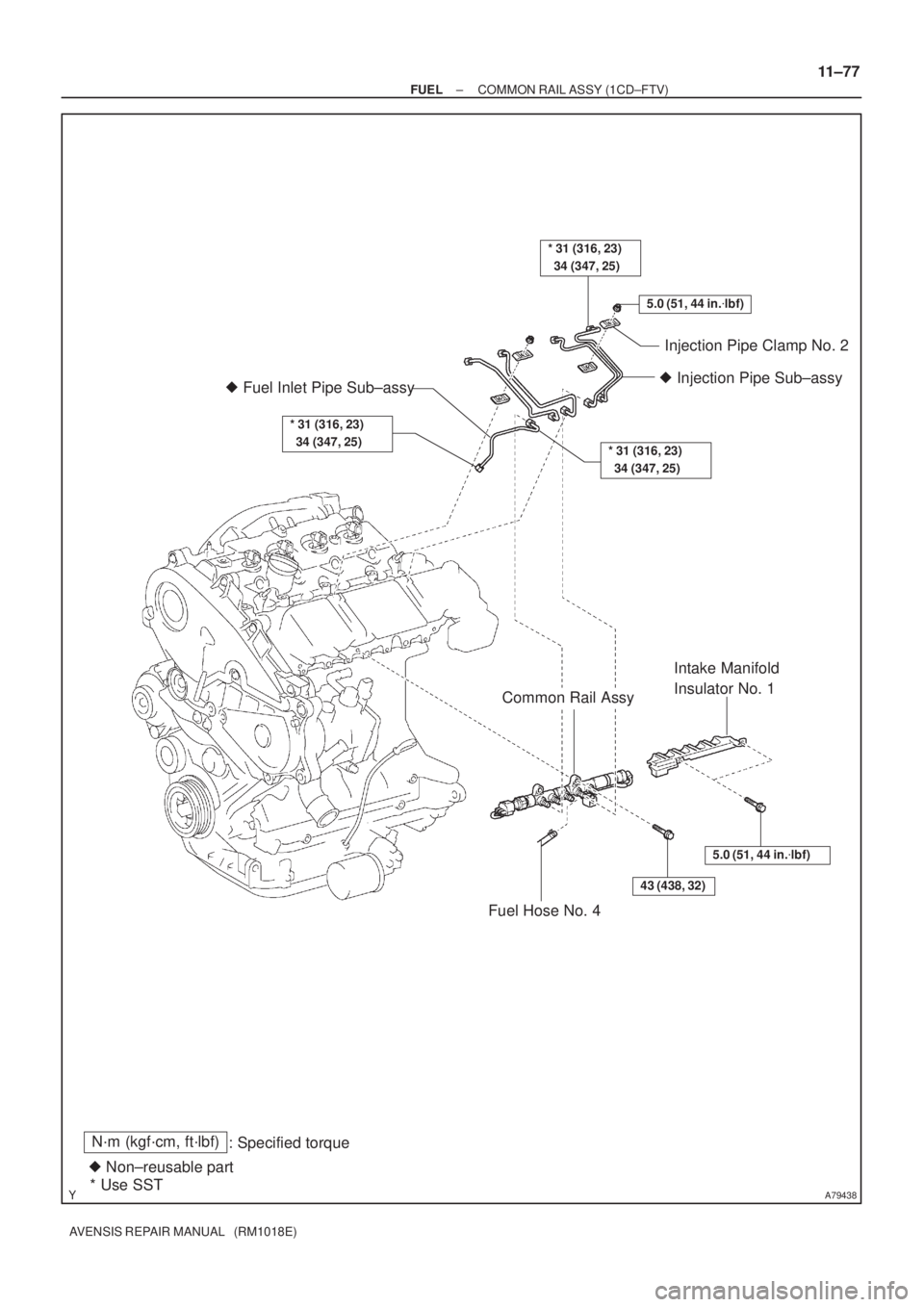
A79438
5.0 (51, 44 in.�lbf)
* 31 (316, 23)
34 (347, 25)
Injection Pipe Clamp No. 2
� Injection Pipe Sub±assy
* 31 (316, 23)
34 (347, 25)
N´m (kgf´cm, ft´lbf)
: Specified torque
� Non±reusable part
* Use SST
Common Rail Assy
Intake Manifold
Insulator No. 1
Fuel Hose No. 4
� Fuel Inlet Pipe Sub±assy
5.0 (51, 44 in.�lbf)
43 (438, 32)
* 31 (316, 23)
34 (347, 25)
± FUELCOMMON RAIL ASSY (1CD±FTV)
11±77
AVENSIS REPAIR MANUAL (RM1018E)
Page 724 of 1690

110UC±01
A79148
SST
A79143
SST
11±78
±
FUEL COMMON RAIL ASSY(1CD±FTV)
AVENSIS REPAIR MANUAL (RM1018E)
REPLACEMENT
1.DRAIN ENGINE COOLANT(See page 16±44)
2. REMOVE RADIATOR SUPPORT OPENING COVER
3. REMOVE ENGINE COVER NO.1
(a) Remove the 5 nuts and the engine cover.
4.REMOVE RADIATOR RESERVE TANK ASSY(See page 16±50) 5. REMOVE FUEL INLET PIPE SUB±ASSY
NOTICE:
After removing the fuel inlet pipe, cover the common rail
and the injection pump with vinyl tape to prevent dust from
being introduced.
(a) Using SST, remove the fuel inlet pipe from the commonrail.
SST 09023±12700
(b) Using SST, remove the fuel inlet pipe from the injection pump.
SST 09023±12700
6. REMOVE INJECTION PIPE SUB±ASSY NO.1
(a) Remove the 2 nuts and the 2 upper infection pipe clamps from the intake manifold.
(b) Using SST, remove the injection pipe from the common
rail side.
SST 09023±12700
(c) Using SST, remove the injection pipe from the injector side.
SST 09023±12700
(d) After removing the fuel pipe, to prevent dust or foreign ob- jects from being introduced, cover the common rail with
vinyl tape and protect the injector inlet with a vinyl or plas-
tic bag.
7. REMOVE INJECTION PIPE SUB±ASSY NO.2 SST 09023±12700
HINT:
Perform the same procedures as injection pipe No. 1.
8. REMOVE INJECTION PIPE SUB±ASSY NO.3 SST 09023±12700
HINT:
Perform the same procedures as injection pipe No. 1.
Page 725 of 1690
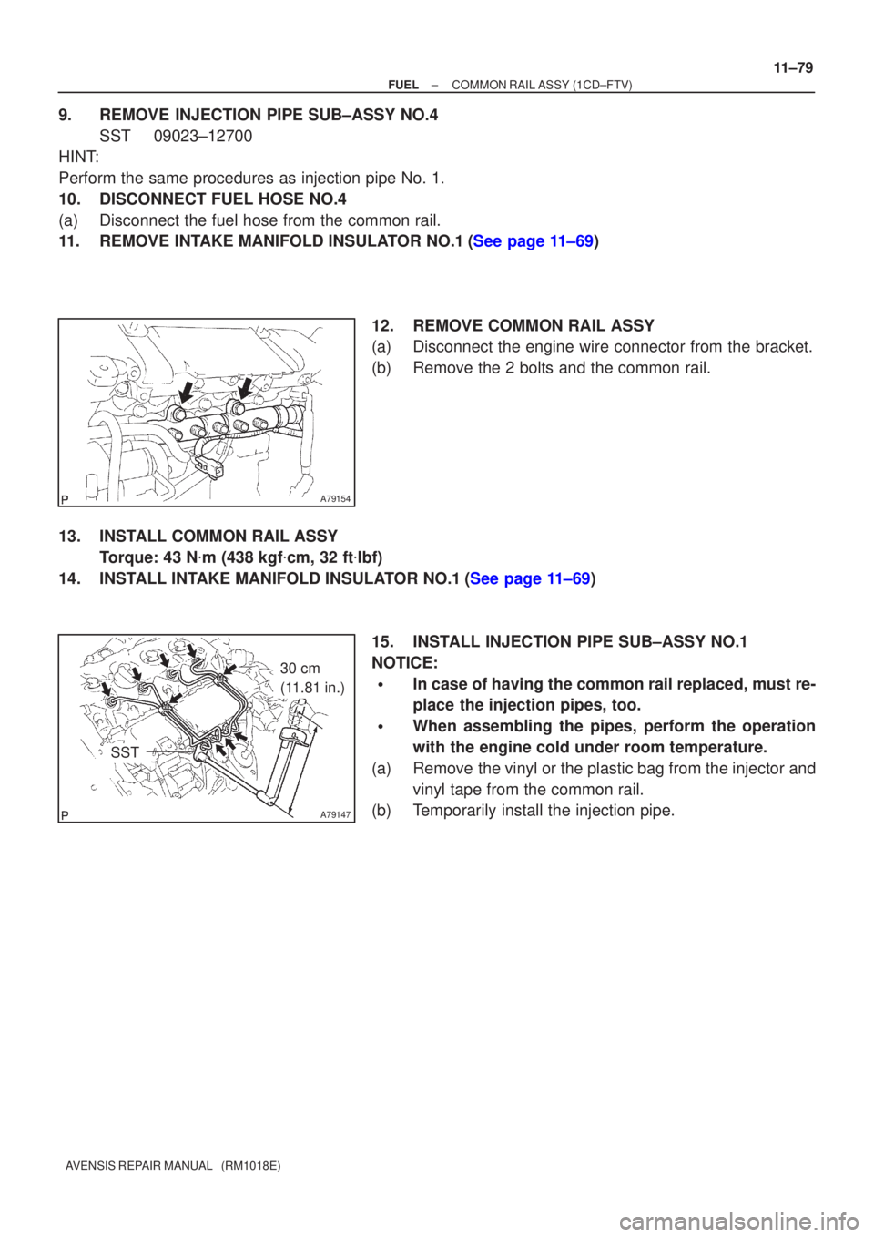
A79154
A79147
30 cm
(11.81 in.)
SST
±
FUEL COMMON RAIL ASSY(1CD±FTV)
11±79
AVENSIS REPAIR MANUAL (RM1018E)
9.REMOVE INJECTION PIPE SUB±ASSY NO.4
SST09023±12700
HINT:
Perform the same procedures as injection pipe No. 1.
10.DISCONNECT FUEL HOSE NO.4
(a)Disconnect the fuel hose from the common rail.
11.REMOVE INTAKE MANIFOLD INSULATOR NO.1(See page 11±69)
12.REMOVE COMMON RAIL ASSY
(a)Disconnect the engine wire connector from the bracket.
(b)Remove the 2 bolts and the common rail.
13.INSTALL COMMON RAIL ASSY Torque: 43 N �m (438 kgf �cm, 32 ft �lbf)
14.INSTALL INTAKE MANIFOLD INSULATOR NO.1(See page 11±69)
15. INSTALL INJECTION PIPE SUB±ASSY NO.1
NOTICE:
�In case of having the common rail replaced, must re-
place the injection pipes, too.
�When assembling the pipes, perform the operation
with the engine cold under room temperature.
(a) Remove the vinyl or the plastic bag from the injector and vinyl tape from the common rail.
(b) Temporarily install the injection pipe.
Page 726 of 1690
11±80
± FUELCOMMON RAIL ASSY (1CD±FTV)
AVENSIS REPAIR MANUAL (RM1018E)
(c) Using SST, tighten the nut of the injection pipe to the com-
mon rail side.
SST 09023±12700
Torque:
42 N�m (428 kgf�cm, 31 ft�lbf) for a used pipe using SST
46 N�m (469 kgf�cm, 34 ft�lbf) for a used pipe not using
SST
31 N�m (316 kgf�cm, 23 ft�lbf) for a new pipe using SST
34 N�m (347 kgf�cm, 25 ft�lbf) for a new pipe not using
SST
HINT:
�Use a torque wrench with a fulcrum length of 30 cm
(11.81 in.)
�Check if the used pipe has deflection or is installed prop-
erly after injection pipe is reassembled. If there is deflec-
tion or if it can not be installed properly, replace the used
pipe with a new pipe.
(d) Using SST, tighten the nut of the injection pipe to the injec-
tor side.
SST 09023±12700
Torque:
42 N�m (428 kgf�cm, 31 ft�lbf) for a used pipe using SST
46 N�m (469 kgf�cm, 34 ft�lbf) for a used pipe not using
SST
31 N�m (316 kgf�cm, 23 ft�lbf) for a new pipe using SST
34 N�m (347 kgf�cm, 25 ft�lbf) for a new pipe not using
SST
HINT:
�Use a torque wrench with a fulcrum length of 30 cm
(11.81 in.)
�Check if the used pipe has deflection or is installed prop-
erly after injection pipe is reassembled. If there is deflec-
tion or if it can not be installed properly, replace the used
pipe with a new pipe.
(e) Install the 2 upper injection pipe clamps with the 2 nuts.
Torque: 5.0 N�m (51 kgf�cm, 44 in.�lbf)
16. INSTALL INJECTION PIPE SUB±ASSY NO.2
SST 09023±12700
HINT:
Perform the same procedures as injection pipe No. 1.
17. INSTALL INJECTION PIPE SUB±ASSY NO.3
SST 09023±12700
HINT:
Perform the same procedures as injection pipe No. 1.
18. INSTALL INJECTION PIPE SUB±ASSY NO.4
SST 09023±12700
HINT:
Perform the same procedures as injection pipe No. 1.
Page 727 of 1690
A79149
30 cm
(11.81 in.)
SST
±
FUEL COMMON RAIL ASSY(1CD±FTV)
11±81
AVENSIS REPAIR MANUAL (RM1018E)
19.INSTALL FUEL INLET PIPE SUB±ASSY
NOTICE:
�In case of having the common rail replaced, must re-
place fuel inlet pipe, too.
�When assembling the pipe, perform the operation
with the engine cold under room temperature.
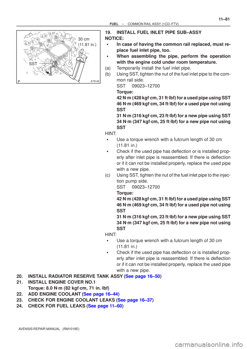
(a)Temporarily install the fuel inlet pipe.
(b)Using SST, tighten the nut of the fuel inlet pipe to the com-
mon rail side.
SST09023±12700
Torque:
42 N�m (428 kgf �cm, 31 ft �lbf) for a used pipe using SST
46 N �m (469 kgf �cm, 34 ft �lbf) for a used pipe not using
SST
31 N �m (316 kgf �cm, 23 ft �lbf) for a new pipe using SST
34 N �m (347 kgf �cm, 25 ft �lbf) for a new pipe not using
SST
HINT:
�Use a torque wrench with a fulcrum length of 30 cm
(11.81 in.)
�Check if the used pipe has deflection or is installed prop-
erly after inlet pipe is reassembled. If there is deflection
or if it can not be installed properly, replace the used pipe
with a new pipe.
(c)Using SST, tighten the nut of the fuel inlet pipe to the injec-
tion pump side.
SST09023±12700
Torque:
42 N�m (428 kgf �cm, 31 ft �lbf) for a used pipe using SST
46 N �m (469 kgf �cm, 34 ft �lbf) for a used pipe not using
SST
31 N �m (316 kgf �cm, 23 ft �lbf) for a new pipe using SST
34 N �m (347 kgf �cm, 25 ft �lbf) for a new pipe not using
SST
HINT:
�Use a torque wrench with a fulcrum length of 30 cm
(11.81 in.)
�Check if the used pipe has deflection or is installed prop-
erly after inlet pipe is reassembled. If there is deflection
or if it can not be installed properly, replace the used pipe
with a new pipe.
20.INSTALL RADIATOR RESERVE TANK ASSY(See page 16±50)
21. INSTALL ENGINE COVER NO.1 Torque: 8.0 N �m (82 kgf �cm, 71 in. �lbf)
22.ADD ENGINE COOLANT(See page 16±44)
23.CHECK FOR ENGINE COOLANT LEAKS(See page 16±37)
24.CHECK FOR FUEL LEAKS(See page 11±60)