2002 NISSAN TERRANO Ignition pump wiring
[x] Cancel search: Ignition pump wiringPage 700 of 1767

Basic Inspection
Precaution:
Perform Basic Inspection without electrical or mechanical
loads applied;
IHeadlamp switch is OFF,
IAir conditioner switch is OFF,
IRear defogger switch is OFF,
ISteering wheel is in the straight-ahead position, etc.
BEFORE STARTING
1. Check service records for any recent
repairs that may indicate a related
problem, or the current need for
scheduled maintenance.
2. Open engine hood and check the fol-
lowing:
IHarness connectors for improper con-
nections
IVacuum hoses for splits, kinks, or
improper connections
IWiring for improper connections,
pinches, or cuts
3.Using priming pump, bleed air from fuel
system. Refer to ªFuel Filter Checkº in
MA section.
CONNECT CONSULT-II TO THE
VEHICLE.
Connect ªCONSULT-IIº to the data link
connector for CONSULT-II and select
ªENGINEº from the menu.
DOES ENGINE START?
Ye s
ENo
Turn ignition switch to
ªLOCKº position, wait 5
seconds and then start
engine. If engine fails to
start, check diagnostic
trouble code (DTC).
Run engine for 10 minutes.
CHECK IDLE SPEED.
Read engine idle speed in ªDATA
MONITORº mode with CONSULT-II.
725 rpm 50 (in N position)
------------------------------------------------------------------------------------------------------------------------------------OR------------------------------------------------------------------------------------------------------------------------------------
Check idle speed using tachometer
tester.
725 rpm 50 (in N position)
(Go toqAon next page.)
SEF142I
NEF463
YEC237A
NEF464
SEF817Y
H
H
H
H
H
TROUBLE DIAGNOSESTD27Ti
EC-338
Page 736 of 1767

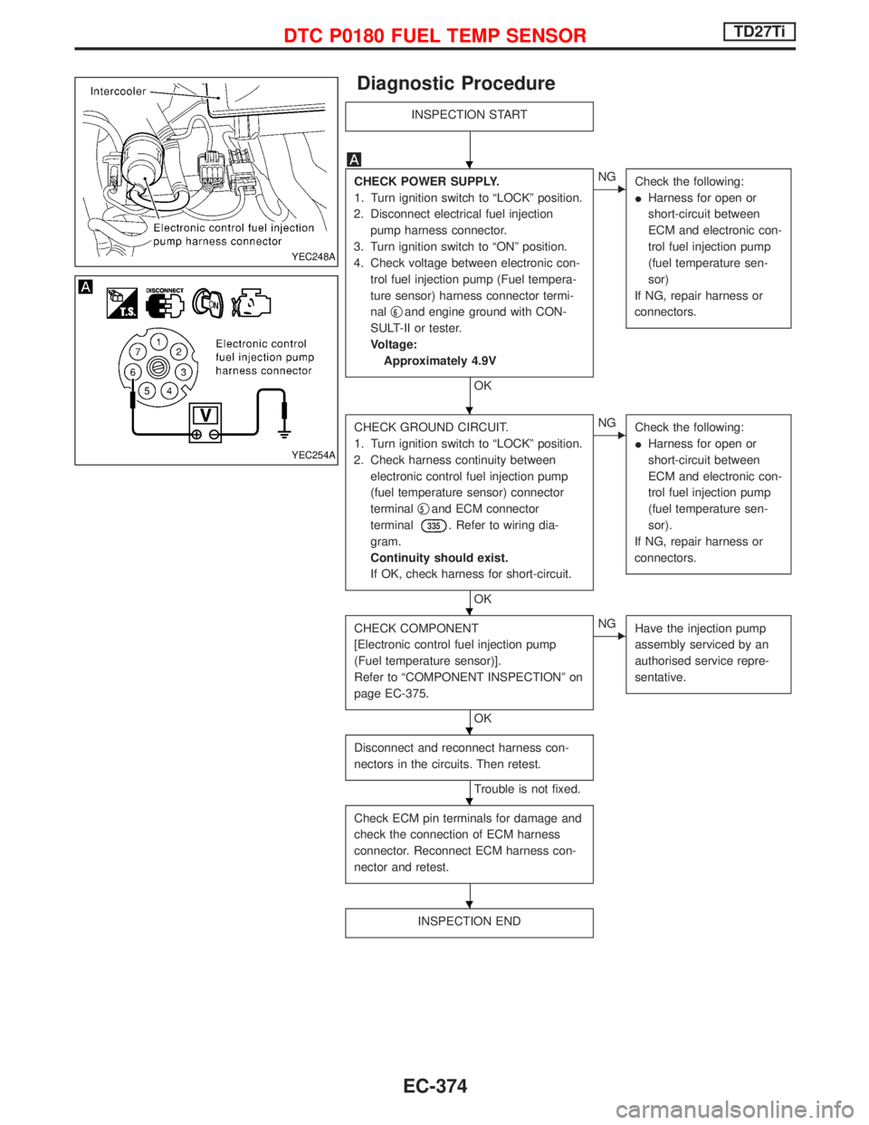
Diagnostic Procedure
INSPECTION START
CHECK POWER SUPPLY.
1. Turn ignition switch to ªLOCKº position.
2. Disconnect electrical fuel injection
pump harness connector.
3. Turn ignition switch to ªONº position.
4. Check voltage between electronic con-
trol fuel injection pump (Fuel tempera-
ture sensor) harness connector termi-
nalq
6and engine ground with CON-
SULT-II or tester.
Voltage:
Approximately 4.9V
OK
ENG
Check the following:
IHarness for open or
short-circuit between
ECM and electronic con-
trol fuel injection pump
(fuel temperature sen-
sor)
If NG, repair harness or
connectors.
CHECK GROUND CIRCUIT.
1. Turn ignition switch to ªLOCKº position.
2. Check harness continuity between
electronic control fuel injection pump
(fuel temperature sensor) connector
terminalq
5and ECM connector
terminal
335. Refer to wiring dia-
gram.
Continuity should exist.
If OK, check harness for short-circuit.
OK
ENG
Check the following:
IHarness for open or
short-circuit between
ECM and electronic con-
trol fuel injection pump
(fuel temperature sen-
sor).
If NG, repair harness or
connectors.
CHECK COMPONENT
[Electronic control fuel injection pump
(Fuel temperature sensor)].
Refer to ªCOMPONENT INSPECTIONº on
page EC-375.
OK
ENG
Have the injection pump
assembly serviced by an
authorised service repre-
sentative.
Disconnect and reconnect harness con-
nectors in the circuits. Then retest.
Trouble is not fixed.
Check ECM pin terminals for damage and
check the connection of ECM harness
connector. Reconnect ECM harness con-
nector and retest.
INSPECTION END
YEC248A
YEC254A
H
H
H
H
H
H
DTC P0180 FUEL TEMP SENSORTD27Ti
EC-374
Page 745 of 1767

Diagnostic Procedure
INSPECTION START
CHECK FOR AIR IN FUEL FILTER.
1. Move priming pump up and down to
purge air from fuel filter.
2. Perform ªDIAGNOSTIC TROUBLE
CODE CONFIRMATION PROCE-
DUREº.
CHECK POWER SUPPLY.
1. Turn ignition switch to ªLOCKº position.
2. Disconnect TVC and shut-off (injection
timing control valve) harness connec-
tor.
3. Turn ignition switch to ªONº position.
4. Check voltage between TVC and shut-
off (injection timing control valve) con-
nector terminalq
9and engine ground
with CONSULT-II or tester.
Voltage: Battery voltage
OK
ENG
Check the following:
IHarness connector
M787,F66
I20A fuse
IECM relay
IHarness for open or
short-circuit between
TVC and shut-off (injec-
tion timing control valve)
harness connector and
fuse box.
If NG, replace 20A fuse or
ECM relay, harness or con-
nectors.
CHECK OUTPUT SIGNAL CIRCUIT.
1. Turn ignition switch to ªLOCKº position.
2. Disconnect ECM harness connector.
3. Check harness continuity between TVC
and shut-off (injection timing control
valve) connector terminalq
8and ECM
terminals
202. Refer to wiring dia-
gram.
Continuity should exist.
If OK, check harness for short-circuit.
OK
ENG
Check the following:
IHarness for open or
short-circuit between
TVC and shut-off (injec-
tion timing control valve)
and ECM
If NG, repair harness or
connectors.
CHECK GROUND CIRCUIT.
1. Disconnect ECM harness connector.
2. Check harness continuity between
ECM connector terminal
349and TVC
and shut-off (injection timing control
valve) connector terminalq
10. Refer to
wiring diagram.
Continuity should exist.
If OK, check harness of short-circuit.
OK
ENG
Repair harness or connec-
tors
qA
YEC256A
NEF463
MEC947D
H
H
H
H
H
DTC P0216 INJ TIMING CONT/V, DTC P1246 F/INJ TIMG F/BTD27Ti
EC-383
Page 774 of 1767

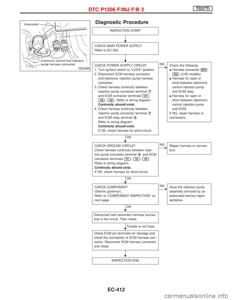
Diagnostic Procedure
INSPECTION START
CHECK MAIN POWER SUPPLY.
Refer to EC-352.
CHECK POWER SUPPLY CIRCUIT.
1. Turn ignition switch to ªLOCKº position.
2. Disconnect ECM harness connector
and electronic injection pump harness
connector.
3. Check harness continuity between
injection pump connector terminalq
7
and ECM connector terminals107,
108,109. Refer to wiring diagram.
Continuity should exist.
4. Check harness continuity between
injection pump connector terminalq
7
and ECM relay terminalq5.
Refer to wiring diagram.
Continuity should exist.
If OK, check harness for short-circuit.
OK
ENG
Check the following.
IHarness connector
M787,
F66(LHD models)
IHarness for open or
short between electronic
control injection pump
and ECM relay
IHarness for open or
short between electronic
control injection pump
and ECM
If NG, repair harness or
connectors.
CHECK GROUND CIRCUIT.
Check harness continuity between injec-
tion pump connector terminalq
4and ECM
connector terminals
101,102,103.
Refer to wiring diagram.
Continuity should exist.
If OK, check harness for short-circuit.
OK
ENG
Repair harness or connec-
tors.
CHECK COMPONENT
(Electric governor).
Refer to ªCOMPONENT INSPECTIONº on
next page.
OK
ENG
Have the injection pump
assembly serviced by an
authorised service repre-
sentative.
Disconnect and reconnect harness connec-
tors in the circuit. Then retest.
Trouble is not fixed.
Check ECM pin terminals for damage and
check the connection of ECM harness con-
nector. Reconnect ECM harness connector
and retest.
INSPECTION END
YEC248A
H
H
H
H
H
H
H
DTC P1206 F/INJ F/B 2TD27Ti
EC-412
Page 778 of 1767

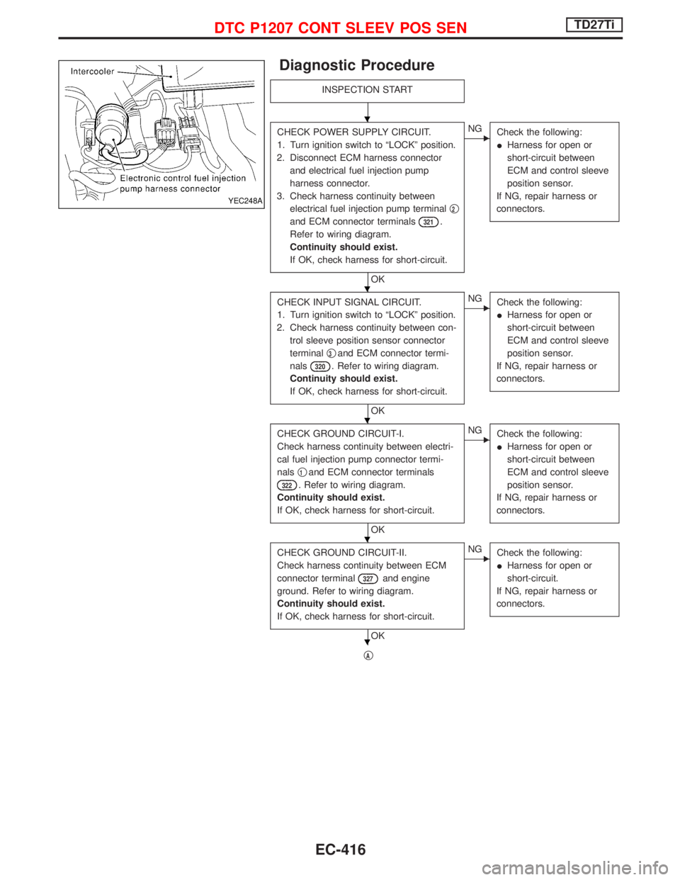
Diagnostic Procedure
INSPECTION START
CHECK POWER SUPPLY CIRCUIT.
1. Turn ignition switch to ªLOCKº position.
2. Disconnect ECM harness connector
and electrical fuel injection pump
harness connector.
3. Check harness continuity between
electrical fuel injection pump terminalq
2
and ECM connector terminals321.
Refer to wiring diagram.
Continuity should exist.
If OK, check harness for short-circuit.
OK
ENG
Check the following:
IHarness for open or
short-circuit between
ECM and control sleeve
position sensor.
If NG, repair harness or
connectors.
CHECK INPUT SIGNAL CIRCUIT.
1. Turn ignition switch to ªLOCKº position.
2. Check harness continuity between con-
trol sleeve position sensor connector
terminalq
3and ECM connector termi-
nals
320. Refer to wiring diagram.
Continuity should exist.
If OK, check harness for short-circuit.
OK
ENG
Check the following:
IHarness for open or
short-circuit between
ECM and control sleeve
position sensor.
If NG, repair harness or
connectors.
CHECK GROUND CIRCUIT-I.
Check harness continuity between electri-
cal fuel injection pump connector termi-
nalsq
1and ECM connector terminals
322. Refer to wiring diagram.
Continuity should exist.
If OK, check harness for short-circuit.
OK
ENG
Check the following:
IHarness for open or
short-circuit between
ECM and control sleeve
position sensor.
If NG, repair harness or
connectors.
CHECK GROUND CIRCUIT-II.
Check harness continuity between ECM
connector terminal
327and engine
ground. Refer to wiring diagram.
Continuity should exist.
If OK, check harness for short-circuit.
OK
ENG
Check the following:
IHarness for open or
short-circuit.
If NG, repair harness or
connectors.
qA
YEC248A
H
H
H
H
H
DTC P1207 CONT SLEEV POS SENTD27Ti
EC-416
Page 791 of 1767

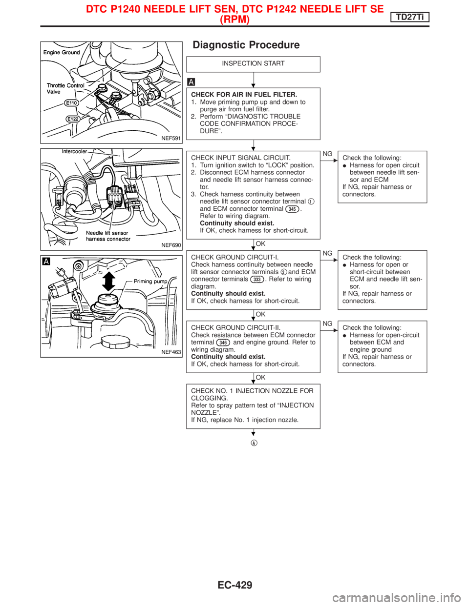
Diagnostic Procedure
INSPECTION START
CHECK FOR AIR IN FUEL FILTER.
1. Move priming pump up and down to
purge air from fuel filter.
2. Perform ªDIAGNOSTIC TROUBLE
CODE CONFIRMATION PROCE-
DUREº.
CHECK INPUT SIGNAL CIRCUIT.
1. Turn ignition switch to ªLOCKº position.
2. Disconnect ECM harness connector
and needle lift sensor harness connec-
tor.
3. Check harness continuity between
needle lift sensor connector terminalq
1and ECM connector terminal345.
Refer to wiring diagram.
Continuity should exist.
If OK, check harness for short-circuit.
OK
ENG
Check the following:
IHarness for open circuit
between needle lift sen-
sor and ECM
If NG, repair harness or
connectors.
CHECK GROUND CIRCUIT-I.
Check harness continuity between needle
lift sensor connector terminalsq
2and ECM
connector terminals333. Refer to wiring
diagram.
Continuity should exist.
If OK, check harness for short-circuit.
OK
ENG
Check the following:
IHarness for open or
short-circuit between
ECM and needle lift sen-
sor.
If NG, repair harness or
connectors.
CHECK GROUND CIRCUIT-II.
Check resistance between ECM connector
terminal
346and engine ground. Refer to
wiring diagram.
Continuity should exist.
If OK, check harness for short-circuit.
OK
ENG
Check the following:
IHarness for open-circuit
between ECM and
engine ground
If NG, repair harness or
connectors.
CHECK NO. 1 INJECTION NOZZLE FOR
CLOGGING.
Refer to spray pattern test of ªINJECTION
NOZZLEº.
If NG, replace No. 1 injection nozzle.
qA
NEF591
NEF690
NEF463
H
H
H
H
H
H
DTC P1240 NEEDLE LIFT SEN, DTC P1242 NEEDLE LIFT SE
(RPM)TD27Ti
EC-429