Page 6 of 249
Table of
ContentsSeats, restraints and supplemental air bag systems
Instruments and controls
Pre-driving checks and adjustments
Heater, air conditioner and audio systems
Starting and driving
In case of emergency
Appearance and care
Maintenance and do-it-yourself
Technical and consumer information
Index
1
2
3
4
5
6
7
8
9
10
Page 51 of 249
1. Headlight and turn signal switch
2. Meters and gauges
3. Windshield wiper/washer switch
4. Center ventilator
5. Audio system
6. Front passenger supplemental air bag
7. Glove box
8. Heater and air conditioner
9. Hazard warning flasher switch
10. Power point
11. Rear window defogger switch
12. Cruise control main/set switch
13. Driver supplemental air bag
14. Steering wheel switch for audio control
15. Tilt/telescopic steering wheel lever
16. Traction control system (TLS) cancel
switch
17. Instrument brightness control
18. Outside mirror remote control
LIC0161
INSTRUMENT PANEL
2-2Instruments and controls
ZX
Page 53 of 249

in the speedometer display. When the igni-
tion is turned to ON, the display scrolls all
the modes of the trip computer and then
shows the mode chosen before the ignition
switch is turned OFF.
If the battery terminal is disconnected,
push the trip computer mode switch
more than 1 second to activate the com-
puter.
When the ignition switch is turned to ON,
modes of the trip computer can be selected
by pushing the trip mode switch on the
steering wheel switch for audio controls or
by the trip computer change button. The
following modes can be selected:
Outside air temperature (ICY±ÉF or
ÉC)
The outside air temperature is displayed in
ÉF or ÉC.
The outside air temperature mode includes
a low temperature warning feature: below
37ÉF (3ÉC), the outside air temperaturemode is automatically selected and ICY will
illuminate in order to draw the driver's atten-
tion. Press the mode switch if you wish to
return to the mode that was selected before
the warning occurred. The ICY indicator will
continue blinking as long as the tempera-
ture remains below 39ÉF (4ÉC).
The ambient temperature sensor is located
in front of the radiator. The sensor may be
affected by road or engine heat, wind direc-
tions and other driving conditions. The dis-
play may differ from the actual ambient
temperature or the temperature displayed
on various signs or billboards.
Distance to empty (dte±mile or km)
The distance to empty (dte) mode provides
you with an estimation of the distance that
can be driven before refueling. The dte is
constantly being calculated, based on the
amount of fuel in the fuel tank and the actual
fuel consumption.
The display is updated every 30 seconds.
The dte mode inlcudes a low range warning
feature: when the fuel level is low, the dte
mode is automatically selected and the dig-
its blink in order to draw the driver's atten-
tion. Press the mode switch if you wish to
WIC0159
2-4Instruments and controls
ZX
Page 63 of 249

Security indicator light (Nissan Ve-
hicle Immobilizer System)
The security indicator light blinks every 3
seconds whenever the ignition switch is in
the LOCK, OFF or ACC position. This func-
tion indicates the Nissan Vehicle Immobi-
lizer System (NVIS) is operational.
If the NVIS is malfunctioning, the light will
remain on while the ignition key is in the ON
position.
If the light still remains on and/or the
engine will not start, see your Nissan
dealer for NVIS service as soon as pos-sible. Please bring all NVIS keys that you
have when visiting your NISSAN dealer
for service.
VEHICLE SECURITY SYSTEM (if
so equipped)
The vehicle security system provides visual
and audio alarm signals if parts of the
vehicle are disturbed.
Security indicator light (Vehicle se-
curity system)
The security indicator light shows the status
of the vehicle security system.
The light operates whenever the ignition
switch is in the LOCK, OFF, or ACC posi-
tion.
The vehicle security system has four
phases. For each phase the operation of the
security indicator light is different.
LIC0167LIC0167
2-14Instruments and controls
ZX
Page 67 of 249

NOTE: The top few rows of wires on the rear
window are not part of the rear window
defogging system. These wires make up the
antenna for the audio system.XENON HEADLIGHTS
WARNING
HIGH VOLTAGE
cWhen xenon headlights are on, they
produce a high voltage. To prevent
an electric shock, never attempt to
modify or disassemble. Always have
your xenon headlights replaced at
an authorized NISSAN dealer.
cXenon headlights provide consider-
ably more light than conventional
headlights. If they are not correctly
aimed, they might temporarily blind
an oncoming driver or the driver
ahead of you and cause a serious
accident. If headlights are not aimed
correctly, immediately take your ve-
hicle to an authorized NISSAN dealer
and have the headlights adjusted
correctly.When the xenon headlight is initially turned
on, its brightness or color varies slightly.
However, the color and brightness will soon
stabilize.
cThe life of xenon headlights will be
shortened by frequent on-off opera-
tion. It is generally desirable not to
turn off the headlights for short inter-
vals, (for example, when the vehicle
stops at a traffic signal). Even when
the daytime running lights are active
(Canada only), the xenon headlights
do not turn on. This way the life of the
xenon headlights is not reduced.
cIf the xenon headlight bulb is close to
burning out, the brightness will dras-
tically decrease, the light will start
blinking, or the color of the light will
become reddish. If one or more of the
above signs appear, contact a
NISSAN dealer.
HEADLIGHT AND TURN
SIGNAL SWITCH
2-18Instruments and controls
ZX
Page 104 of 249

4Heater, air conditioner and audio systems
Ventilators ..............................................................4-2
Center ventilators ..............................................4-2
Side ventilators ..................................................4-2
Heater and air conditioner (manual) ......................4-3
Controls .............................................................4-3
Heater operation ................................................4-4
Air conditioner operation (if so
equipped) ...........................................................4-5
Air flow charts ....................................................4-6
Heater and air conditioner (automatic) (if so
equipped) ...............................................................4-9
Automatic operation ..........................................4-9
Manual operation .............................................4-10
Operating tips ..................................................4-11
Servicing air conditioner .......................................4-11Audio system ........................................................4-12
Radio ...............................................................4-12
FM radio reception ..........................................4-12
AM radio reception ..........................................4-12
Audio operation precautions ...........................4-13
FM-AM radio with compact disc (CD)
player ...............................................................4-16
FM-AM radio with compact disc (CD)
changer (if so equipped) .................................4-21
CD care and cleaning......................................4-28
Steering wheel switch for audio control
(if so equipped)................................................4-28
Antenna ...........................................................4-29
Car phone or CB radio .........................................4-29
ZX
Page 105 of 249
CENTER VENTILATORS
Adjust air flow direction by moving the ven-
tilator slide.
SIDE VENTILATORS
You can open or close the side ventilators
by using the dial located at the side of the
ventilators. Adjust air flow direction by mov-
ing the ventilator slide.
The airflow can be turned off by turning the
dial to the outboard position.
LHA0107LHA0108WHA0135
VENTILATORS
4-2Heater, air conditioner and audio systems
ZX
Page 106 of 249

WARNING
cThe air conditioner cooling function
operates only when the engine is
running.
c
Do not leave children, impaired adults,
or pets alone in your vehicle. On hot
sunny days, temperatures in a closed
vehicle could quickly become high
enough to cause severe or possibly
fatal injuries to people or animals.
cDo not use the recirculation mode
for long periods as it may cause the
interior air to become stale and the
windows to fog up.
cPositioning of the heating or air con-
ditioning controls should not be
done while driving, so full attention
may be given to vehicle operation.
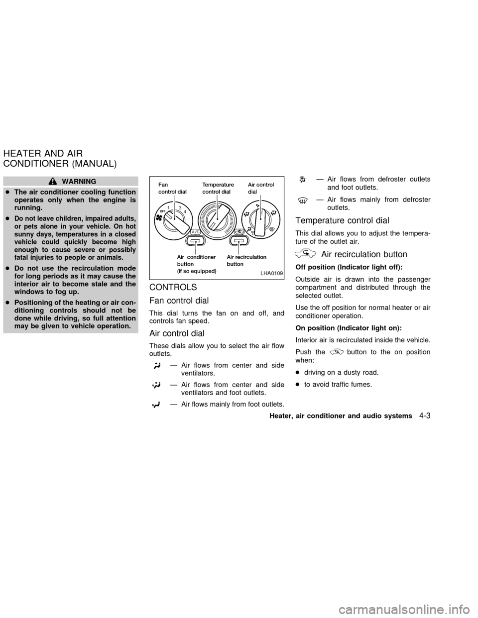
CONTROLS
Fan control dial
This dial turns the fan on and off, and
controls fan speed.
Air control dial
These dials allow you to select the air flow
outlets.
Ð Air flows from center and side
ventilators.
Ð Air flows from center and side
ventilators and foot outlets.
Ð Air flows mainly from foot outlets.
Ð Air flows from defroster outlets
and foot outlets.
Ð Air flows mainly from defroster
outlets.
Temperature control dial
This dial allows you to adjust the tempera-
ture of the outlet air.
Air recirculation button
Off position (Indicator light off):
Outside air is drawn into the passenger
compartment and distributed through the
selected outlet.
Use the off position for normal heater or air
conditioner operation.
On position (Indicator light on):
Interior air is recirculated inside the vehicle.
Push the
button to the on position
when:
cdriving on a dusty road.
cto avoid traffic fumes.
LHA0109
HEATER AND AIR
CONDITIONER (MANUAL)
Heater, air conditioner and audio systems4-3
ZX