Page 217 of 430
214 Infrared reflecting windshield
Te ch n i c a l
data Instruments
and controlsOperationDrivingInstrument
cluster displayPractical hints Car care Index
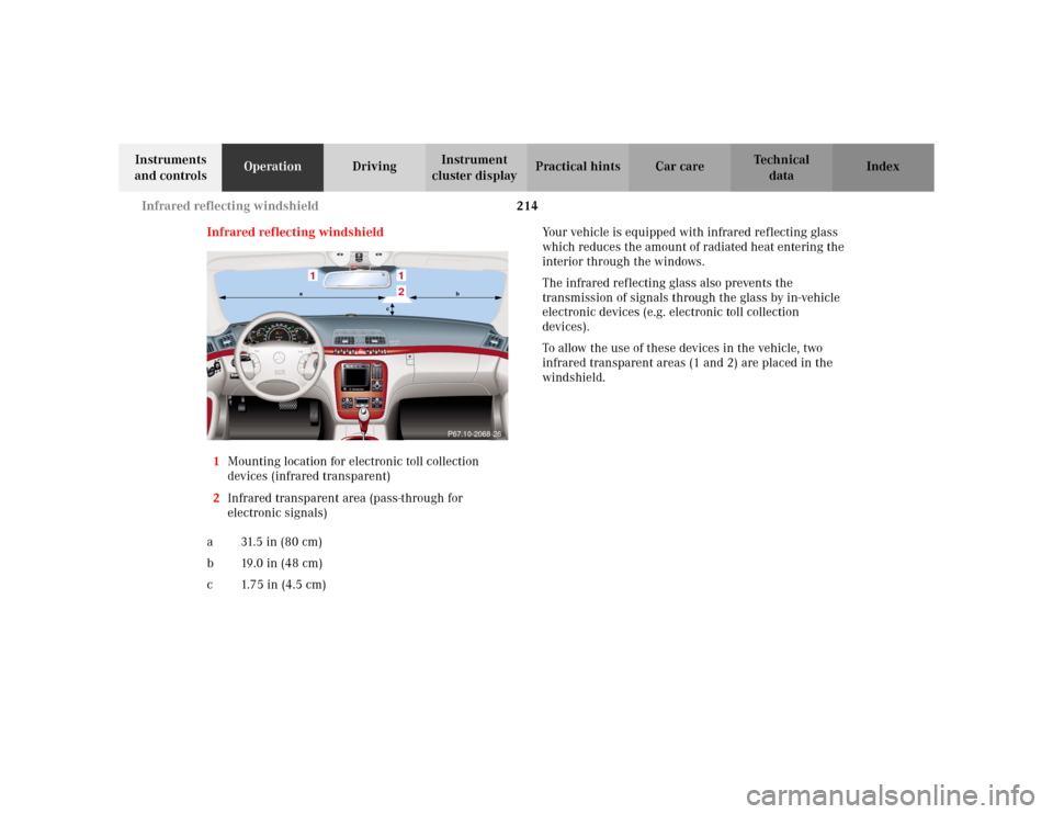
Infrared reflecting windshield
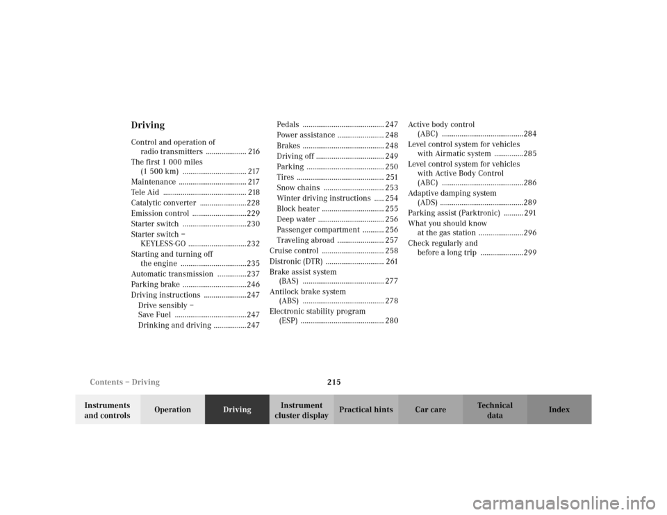
1Mounting location for electronic toll collection
devices (infrared transparent)
2Infrared transparent area (pass-through for
electronic signals)
a 31. 5 i n ( 8 0 c m )
b19.0in (48cm)
c 1.75 in (4.5 cm)Your vehicle is equipped with infrared reflecting glass
which reduces the amount of radiated heat entering the
interior through the windows.
The infrared reflecting glass also prevents the
transmission of signals through the glass by in-vehicle
electronic devices (e.g. electronic toll collection
devices).
To allow the use of these devices in the vehicle, two
infrared transparent areas (1 and 2) are placed in the
windshield.
1
12
P67.10-2068-26
ab
c
Page 218 of 430

215 Contents – Driving
Te ch n i c a l
data Instruments
and controlsOperationDrivingInstrument
cluster displayPractical hints Car care Index
DrivingControl and operation of
radio transmitters ..................... 216
The first 1 000 miles
(1 500 km) ................................. 217
Maintenance ................................... 217
Tele Aid ........................................... 218
Catalytic converter ........................228
Emission control ............................229
Starter switch .................................230
Starter switch –
KEYLESS-GO ..............................232
Starting and turning off
the engine ..................................235
Automatic transmission ...............237
Parking brake .................................246
Driving instructions ......................247
Drive sensibly –
Save Fuel .....................................247
Drinking and driving .................247Pedals .......................................... 247
Power assistance ........................ 248
Brakes .......................................... 248
Driving off ................................... 249
Parking ........................................ 250
Tires ............................................. 251
Snow chains ............................... 253
Winter driving instructions ..... 254
Block heater ................................ 255
Deep water .................................. 256
Passenger compartment ........... 256
Traveling abroad ........................ 257
Cruise control ................................ 258
Distronic (DTR) .............................. 261
Brake assist system
(BAS) .......................................... 277
Antilock brake system
(ABS) .......................................... 278
Electronic stability program
(ESP) ........................................... 280Active body control
(ABC) ..........................................284
Level control system for vehicles
with Airmatic system ...............285
Level control system for vehicles
with Active Body Control
(ABC) ..........................................286
Adaptive damping system
(ADS) ...........................................289
Parking assist (Parktronic) .......... 291
What you should know
at the gas station .......................296
Check regularly and
before a long trip ......................299
Page 219 of 430

216 Control and operation of radio transmitters
Te ch n i c a l
data Instruments
and controlsOperationDrivingInstrument
cluster displayPractical hints Car care Index
Control and operation of radio transmitters
COMAND, radio and telephone
1 Observe all legal requirements.
Telephones and two-way radio
Radio transmitters, such as a portable telephone or a
citizens band unit should only be used inside the
vehicle if they are connected to an antenna that is
installed on the outside of the vehicle.
Refer to the radio transmitter operation instructions
regarding use of an external antenna.
Wa r n i n g !
Please do not forget that your primary
responsibility is to drive the vehicle. Only operate
the COMAND (Cockpit Management and Data
System), radio or telephone
1 if road and traffic
conditions permit.
Bear in mind that at a speed of just 30 mph
(approximately 50 km / h), your vehicle is covering
a distance of approximately 50 feet (approximately
14 m) every second.
Wa r n i n g !
Never operate radio transmitters equipped with a
built-in or attached antenna (i.e. without being
connected to an external antenna) from inside the
vehicle while the engine is running. Doing so could
lead to a malfunction of the vehicle’s electronic
system, possibly resulting in an accident and
personal injury.
Page 220 of 430

217 The first 1 000 miles
Te ch n i c a l
data Instruments
and controlsOperationDrivingInstrument
cluster displayPractical hints Car care Index The first 1 000 miles (1 500 km)
The more cautiously you treat your vehicle during the
break-in period, the more satisfied you will be with its
performance later on. Therefore, drive your vehicle
during the first 1 000 miles (1 500 km) at moderate
vehicle and engine speeds.
During this period, avoid heavy loads (full throttle
driving) and excessive engine speeds.
Avoid accelerating by kickdown. It is not recommended
to brake the vehicle by manually shifting to a lower gear.
We recommend that you select positions “3”, “2” or “1”
only at moderate speeds (for hill driving).
After 1 000 miles (1 500 km) speeds may be gradually
increased to the permissible maximum.Maintenance
We strongly recommend that you have your vehicle
serviced by your authorized Mercedes-Benz Center, in
accordance with the Service Booklet at the times called
for by the FSS.
Failure to have the vehicle maintained in accordance
with the Service Booklet at the designated times /
mileage may result in vehicle damage not covered by
the Mercedes-Benz Limited Warranty.
For information on the Flexible service system (FSS),
see page 149.
Page 221 of 430

218 Tele Aid
Te ch n i c a l
data Instruments
and controlsOperationDrivingInstrument
cluster displayPractical hints Car care Index
Tele Aid
Important!
The initial activation of the Tele Aid system may only be
performed by completing the subscriber agreement and
placing an acquaintance call using the “SOS” button.
Failure to complete either of these steps will result in a
system that is not activated. If the system is not
activated the indicator lamp in the “SOS” button stays
on after turning electronic key in starter switch to
position 2 (vehicles with KEYLESS-GO:
operating position, see page 232) and the message
“TELE AID – NOT ACTIVATED” will be shown in the
multifunction display for approx. 10 seconds.
If you have any questions regarding activation, please
call the Response Center at 1-800-756-9018 (in the USA)
or 1-888-923-8367 (in Canada).
(Te l ematic Alarm Identification on Demand)
The Tele Aid system consists of three types of response;
automatic and manual emergency, roadside assistance
and information.
The Tele Aid system is operational providing that the
vehicle’s battery is charged, properly connected, not
damaged and cellular and GPS coverage is available.The speaker volume of a Tele Aid call can be adjusted
when using the volume control on the multifunction
steering wheel, for raising press buttonæand for
lowering press buttonç.
To activate, press the “SOS” button, the Roadside
Assistance button• or the Information button¡,
depending on the type of response required.
Shortly after the completion of your Acquaintance Call,
you will receive a user ID and password via first call
mail. By visiting www.mbusa.com and selecting
“Tele Aid” (USA only), you will have access to account
information, remote door unlock, Info Services
* profile
and more.
* Optional System self-check
Initially, after turning the electronic key in starter
switch to position 2, malfunctions are detected and
indicated (the indicator lamps in the “SOS” button, the
Roadside Assistance button• and the Information
button¡ stay on longer than 10 seconds or do not
come on). The message “TELE AID – VISIT
WORKSHOP” appears for approx. 10 seconds in the
multifunction display.
Page 222 of 430

219 Tele Aid
Te ch n i c a l
data Instruments
and controlsOperationDrivingInstrument
cluster displayPractical hints Car care Index Important!
Always make sure that the indicator lamps in the
“SOS” button, in the “Roadside Assistance” button and
in the “Information” button do not remain illuminated
constantly in red and the message “TELE AID – VISIT
WORKSHOP” is not displayed in the multifunction
display after the system self check.
If a malfunction is indicated as outlined above, have the
system checked at the nearest Mercedes-Benz Center as
soon as possible.
Emergency calls
An emergency call is initiated automatically:
•following an accident in which the Emergency
Tensioning Retractors (ETR’s) or airbags deploy,
•if the antitheft alarm or the tow away alarm stays on
for more than 20 seconds, see pages 60 and 61.
An emergency call can also be initiated manually by
opening the cover next to the inside rear view mirror
labeled “SOS”, then briefly pressing the button located
under the cover. See below for instructions on initiating
an emergency call manually.Once the emergency call is in progress, the indicator
lamp in the “SOS” button will begin to flash. The
message “EMERGENCY CALL – CONNECTING CALL”
appears in the multifunction display. When the
connection is established, the message “EMERGENCY
CALL – CALL CONNECTED” appears in the
multifunction display. All information relevant to the
emergency, such as the location of the vehicle
(determined by the GPS satellite location system),
vehicle model, identification number and color are
generated.
A voice connection between the Response Center and
the occupants of the vehicle will be established
automatically soon after the emergency call has been
initiated. When a voice connection is established the
audio system mutes and the message “TELE AID –
EMERGENCY CALL ACTIVE” appears in the
multifunction display. The Response Center will attempt
to determine more precisely the nature of the accident
provided they can speak to an occupant of the vehicle.
Page 223 of 430

220 Tele Aid
Te ch n i c a l
data Instruments
and controlsOperationDrivingInstrument
cluster displayPractical hints Car care Index
The Tele Aid system is available if:
•it has been activated and is operational. Activation
requires a subscription for monitoring services and
cellular air time
•the relevant cellular phone network and GPS signals
are available and pass the information on to the
response center.
Note:
Location of the vehicle on a map is possible if the
vehicle is able to receive signals from the GPS satellite
network and pass the information on to the response
center.
Wa r n i n g !
If the indicator lamp in the “SOS” button is
illuminated continuously and there was no voice
connection to the Response Center established,
then the Tele Aid system could not initiate an
emergency call (e.g. the relevant cellular phone
network is not available). The message
“EMERGENCY CALL – CALL FAILED” appears in
the multifunction display for approx. 10 seconds.Should this occur, assistance must be summoned
by other means.
Page 224 of 430
221 Tele Aid
Te ch n i c a l
data Instruments
and controlsOperationDrivingInstrument
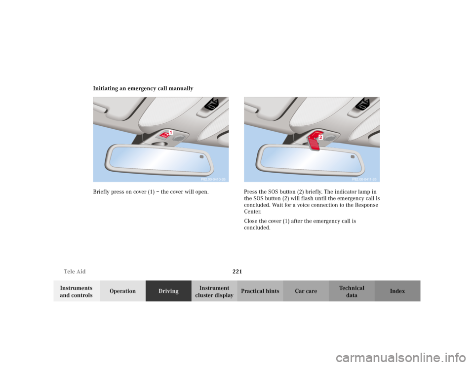
cluster displayPractical hints Car care Index Initiating an emergency call manually
Briefly press on cover (1) – the cover will open. Press the SOS button (2) briefly. The indicator lamp in
the SOS button (2) will flash until the emergency call is
concluded. Wait for a voice connection to the Response
Center.
Close the cover (1) after the emergency call is
concluded.
1
P82.00-0410-26
P82.00-0411-26
2