2002 MERCEDES-BENZ S55AMG messages
[x] Cancel search: messagesPage 7 of 430

4 Contents
Instrument cluster displayMalfunction and indicator
lamps in the
instrument cluster ....................302
On-board diagnostic
system ..........................................302
Check engine malfunction
indicator lamp .............................302
Brake warning lamp ..................304
Supplemental restraint system
(SRS) indicator lamp ..................305
Fuel reserve warning .................305
ABS malfunction
indicator lamp .............................306
Electronic stability program
(ESP) — warning lamp ...............307
Distronic (DTR) –
warning lamp ..............................307
Seat belt nonusage
warning lamp ..............................308
Malfunction and indicator
lamp in the
center console ...........................308
AIRBAG OFF indicator lamp .....308Malfunction and warning
messages in the
multifunction display .............. 309
DISPLAY DEFECTIVE ................. 310
BATTERY/ALTERNATOR ........... 311
ENTRANCE POSITION ...............312
BRAKE ASSIST ............................312
BRAKE LINING WEAR ............... 313
BRAKE FLUID ............................. 313
PARKING BRAKE ........................ 314
TRUNK OPEN .............................. 314
ELEC. STABIL. PROG.
(Electronic stability
program) ...................................... 315
COOLANT
(coolant level) .............................. 316
COOLANT
(coolant temperature) ................ 317
LIGHTING SYSTEM .................... 318
LIGHT SENSOR .......................... 320
ACTIVE BODY CONTROL
(ABC) ........................................... 320
TIRE PRESSURE ........................ 322
ENGINE OIL LEVEL ................... 324CRUISE CONTROL .....................325
KEY ...............................................325
DOOR ...........................................326
HOOD ...........................................326
TELE AID .....................................327
CHIP-CARD
(KEYLESS-GO) ............................328
SELECTOR LEVER ......................329
TELEPHONE – FUNCTION .......329
WASHER FLUID .........................330
AIR SPRING (AirMatic) ............. 331
DISTRONIC (DTR) ......................332
AIR CLEANER .............................333
Practical hintsFirst aid kit .....................................336
Stowing things in the vehicle ......336
Fuses ................................................337
Hood .................................................339
Checking engine oil level .............342
Automatic transmission
fluid level ...................................343
Active body control (ABC)
fluid level ...................................343
Page 116 of 430
113 Instrument cluster
Te ch n i c a l
data Instruments
and controlsOperationDrivingInstrument
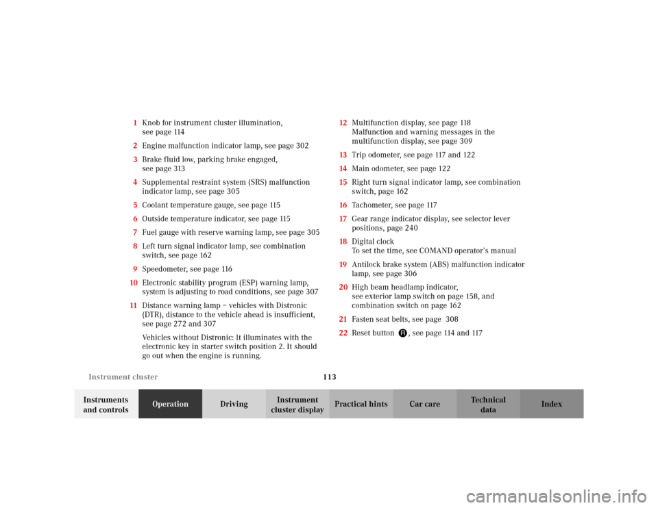
cluster displayPractical hints Car care Index 1Knob for instrument cluster illumination,
seepage114
2Engine malfunction indicator lamp, see page 302
3Brake fluid low, parking brake engaged,
seepage313
4Supplemental restraint system (SRS) malfunction
indicator lamp, see page 305
5Coolant temperature gauge, see page 115
6Outside temperature indicator, see page 115
7Fuel gauge with reserve warning lamp, see page 305
8Left turn signal indicator lamp, see combination
switch, see page 162
9Speedometer, see page 116
10Electronic stability program (ESP) warning lamp,
system is adjusting to road conditions, see page 307
11Distance warning lamp – vehicles with Distronic
(DTR), distance to the vehicle ahead is insufficient,
see page 272 and 307
Vehicles without Distronic: It illuminates with the
electronic key in starter switch position 2. It should
go out when the engine is running.12Multifunction display, see page 118
Malfunction and warning messages in the
multifunction display, see page 309
13Trip odometer, see page 117 and 122
14Main odometer, see page 122
15Right turn signal indicator lamp, see combination
switch, page 162
16Tachometer, see page 117
17Gear range indicator display, see selector lever
positions, page 240
18Digital clock
To set the time, see COMAND operator’s manual
19Antilock brake system (ABS) malfunction indicator
lamp, see page 306
20High beam headlamp indicator,
see exterior lamp switch on page 158, and
combination switch on page 162
21Fasten seat belts, see page 308
22Reset button J, see page 114 and 117
Page 122 of 430

119 Multifunction steering wheel, multifunction display
Te ch n i c a l
data Instruments
and controlsOperationDrivingInstrument
cluster displayPractical hints Car care Index Depending on your vehicle’s equipment, you may use
the buttons on the multifunction steering wheel to call
up, control and set the following systems in the
multifunction display:
1Trip and main odometer, see page 122
Flexible service system (FSS), see page 149
Tire inflation pressure monitor, see page 152
Engine oil level indicator, see page 156
2Audio systems, see page 124
Radio, seepage124
CD player, see page 125
Cassette player, see page 126
3Telephone, see page 1274Navigation system, see page 132
5Distronic (DTR), see page 133
6Trip computer, see page 134
After start
After reset
Range
7Malfunction message memory, see page 136
8Individual settings, see page 138
9Malfunction messages are stored in memory (7), see
page 136.
Press the è or ÿ button repeatedly until the
required system is displayed.
The display advances by one system each time the
button is pressed.
You may call up additional displays within some of these
categories by pressing the j or k button.
Page 139 of 430
136 Multifunction steering wheel, multifunction display
Te ch n i c a l
data Instruments
and controlsOperationDrivingInstrument
cluster displayPractical hints Car care Index
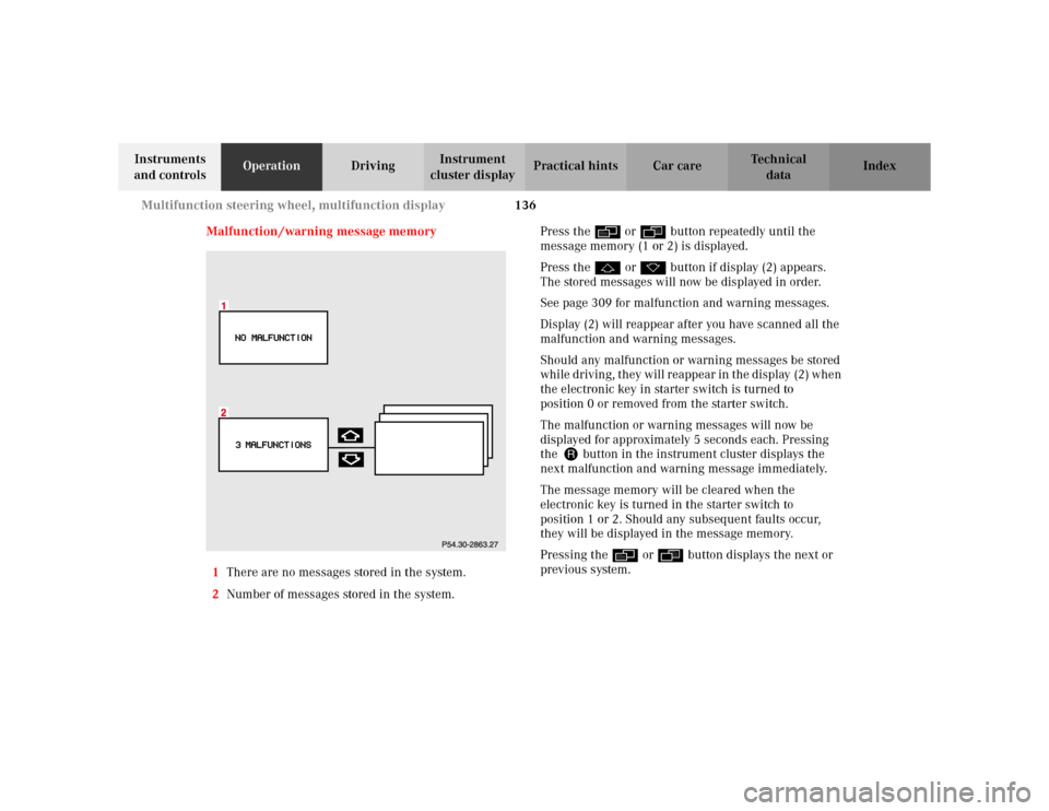
Malfunction /warning message memory
1There are no messages stored in the system.
2Number of messages stored in the system.Press the è or ÿ button repeatedly until the
message memory (1 or 2) is displayed.
Press the j or k button if display (2) appears.
The stored messages will now be displayed in order.
See page 309 for malfunction and warning messages.
Display (2) will reappear after you have scanned all the
malfunction and warning messages.
Should any malfunction or warning messages be stored
while driving, they will reappear in the display (2) when
the electronic key in starter switch is turned to
position 0 or removed from the starter switch.
The malfunction or warning messages will now be
displayed for approximately 5 seconds each. Pressing
the Jbutton in the instrument cluster displays the
next malfunction and warning message immediately.
The message memory will be cleared when the
electronic key is turned in the starter switch to
position 1 or 2. Should any subsequent faults occur,
they will be displayed in the message memory.
Pressing the è or ÿ button displays the next or
previous system.
Page 140 of 430
137 Multifunction steering wheel, multifunction display
Te ch n i c a l
data Instruments
and controlsOperationDrivingInstrument
cluster displayPractical hints Car care Index Important!
Malfunction and warning messages are only indicated
for certain systems and displayed to a low level of detail.
The malfunction and warning messages are simply a
reminder with respect to the operation of certain
systems and do not replace the driver’s responsibility to
maintain the vehicle’s operating safety by having all
required maintenance and safety checks performed on
the vehicle and by bringing the vehicle to an authorized
Mercedes-Benz Center to address the malfunction and
warning messages. See page 309.
Page 152 of 430
149 Flexible service system
Te ch n i c a l
data Instruments
and controlsOperationDrivingInstrument
cluster displayPractical hints Car care Index Flexible service system (FSS)
(service indicator)
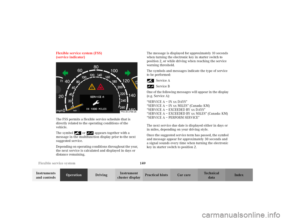
The FSS permits a flexible service schedule that is
directly related to the operating conditions of the
vehicle.
The symbol 9 or ½ appears together with a
message in the multifunction display prior to the next
suggested service.
Depending on operating conditions throughout the year,
the next service is calculated and displayed in days or
distance remaining.The message is displayed for approximately 10 seconds
when turning the electronic key in starter switch to
position 2, or while driving when reaching the service
warning threshold.
The symbols and messages indicate the type of service
to be performed:
9Service A
½Service B
One of the following messages will appear in the display
(e.g. Service A):
“SERVICE A – IN xx DAYS”
“SERVICE A – IN xx MILES” (Canada: KM)
“SERVICE A – EXCEEDED BY xx DAYS”
“SERVICE A – EXCEEDED BY xx MILES” (Canada: KM)
“SERVICE A – PERFORM SERVICE”
The next service due date is displayed either in days or
in miles, depending on your driving style.
Once the suggested service term has passed, the symbol
and message appear for approximately 30 seconds and
a signal sounds every time when turning the electronic
key in starter switch to position 2.
P54.30-2768-26
Page 158 of 430

155 Tire inflation pressure monitor
Te ch n i c a l
data Instruments
and controlsOperationDrivingInstrument
cluster displayPractical hints Car care Index Notes:
To ensure proper functioning of the tire inflation
pressure monitor, the tire inflation pressure should be
checked and corrected according to the label affixed
inside the fuel filler flap. For a detailed description,
refer to page 356.
The message “REACTIVATE – TIRE PRESS. MONITOR”
appears if the tire inflation pressure shows an increase
of 4.4 psi (0.3 bar) or more. Reactivate the tire inflation
pressure monitor.
The tire inflation pressure monitor only functions on
wheels equipped with the proper electronic sensors.
Inquire at your authorized Mercedes-Benz Center about
retrofitting other than original Mercedes-Benz wheels
with electronic sensors.
Transporting a deflated road wheel in the vehicle, e.g.
after having a flat, the tire inflation pressure monitor
should only be activated once the flat tire and rim are
removed from the vehicle.To prevent possible damage to the electronic sensors,
have tire changes only performed at an authorized
Mercedes-Benz Center.
For malfunction and warning messages, see page 309.
When checking the tire inflation pressure of the road
wheels, also check the spare tire.
The tire inflation pressure of the spare wheel, mounted
or not mounted, is not monitored by the tire inflation
pressure monitor.
See page 346 for location of the spare wheel, and
page 356 for tire inflation pressure.
Page 160 of 430
157 Engine oil level indicator
Te ch n i c a l
data Instruments
and controlsOperationDrivingInstrument
cluster displayPractical hints Car care Index One of the following messages will subsequently appear
on the indicator:
“ENGINE OIL LEVEL – O.K.”
No oil needs to be added.
“ENGINE OIL LEVEL – ADD 1.0 QUART”
(Canada: 1.0 L)
“ENGINE OIL LEVEL – ADD 1.5 QUART”
(Canada: 1.5 L)
“ENGINE OIL LEVEL – ADD 2.0 QUART”
(Canada: 2.0 L)
See “Checking engine oil level”, on page 342 for
instructions on adding engine oil.
“ENGINE OIL LEVEL – REDUCE OIL LEVEL”
Do not overfill the engine.
Excessive oil must be siphoned or drained off. It could
cause damage to the engine and catalytic converter not
covered by the Mercedes-Benz Limited Warranty.
The “MEASURING NOT POSSIBLE!” message will be
displayed if a proper oil level check cannot be
performed. The engine oil level check can be repeated
after a short while.S 430, S 500 and S 55 AMG only:
Perform the engine oil level check with the dipstick, if it
cannot be completed via the multifunction display.
See “Checking engine oil level”, page 342.
In this case we recommend that you have the system
checked at a Mercedes-Benz Center.
Notes:
See malfunction and warning messages on page 309
and page 324 if an engine oil level indicator appears in
the multifunction display when the engine is running.
The engine oil level cannot be checked while the engine
is running. The “ENGINE OIL LEVEL – NOT WHEN
ENGINE ON” message will appear.
Engine oil consumption
Engine oil consumption checks should only be made
after the break-in period. During the break-in period,
higher oil consumption may be noticed and is normal.
Frequent driving at high engine speeds results in
increased consumption.