2002 MERCEDES-BENZ G500 wheel
[x] Cancel search: wheelPage 249 of 385
246 Driving systems
Te ch n i c a l
data Instruments
and controlsOperationDrivingInstrument
cluster displayPractical hints Car care Index
If the ESP is switched off, it will be automatically
activated when exceeding a vehicle speed of 37 mph
(60 km / h) or exceeding a severity threshold of side
acceleration.
If one drive wheel loses traction and begins to spin, the
brake is applied until the wheel regains sufficient
traction. The traction control is available between
vehicle speed 0 mph (km / h) and 37 mph (60 km / h).Note:
Avoid spinning of one drive wheel. This may cause
serious damage to the drive train which is not covered
by the Mercedes-Benz Limited Warranty.
The ESP warning lamp, located in the speedometer dial,
starts to flash at any vehicle speed as soon as the tires
lose traction and the wheels begin to spin.
To return to the enhanced vehicle stability offered by
ESP: press lower half of the switch (the ESP warning
lamp in the speedometer dial goes out).
Important!
If the ESP warning lamp flashes:
•during take-off, apply as little throttle as possible,
•while driving, ease up on the accelerator.
J_G463.book Seite 246 Mittwoch, 19. September 2001 8:06 08
Page 254 of 385
251 Driving systems
Te ch n i c a l
data Instruments
and controlsOperationDrivingInstrument
cluster displayPractical hints Car care Index A few words about differentials and differential
locks
When a vehicle negotiates a turn, wheels on the outside
of the curve must travel farther and rotate faster than
the inside wheels. The differential, the operation of a set
of gears that allow the powered wheels in a vehicle to
turn a different speeds, provides for this essential
function.
The drawback is that the differential also sends most of
the engine's power to the wheel with the least load or
strain on it. For example, if one of a vehicle's powered
wheels sits on a patch of snow and spins because there
is no traction, all of the engine's power will go to that
wheel because the power will take the path of least
resistance. Meanwhile, the opposite wheel, sitting on
dry pavement where it could get enough grip to start the
vehicle moving, sits idle because it gets no power.
The Electronic Traction System (ETS) addresses this
problem and provides for good control and steering
ability by automatically slowing the slipping wheel and
thus increasing the power to the other non-slipping
d rive whee ls to get t he ve hicle m ovin g. The ESP and ETS
in this vehicle feature such intelligent limited-slip
differential technology, ideally suited for on-road and light off-road driving. The position “LOW” of the
transfer case (see pages 247and 226) also enhances
off-road driving capabilities.
More extreme off-road conditions may call for another
cure which is to engage a differential lock, preventing
the differential from operating altogether. This vehicle
offers as standard equipment three differential locks:
front, transfer case (center), and rear. Each can be
engaged simply by pushing a dashboard-mounted
button (see pages 253 and 254 for engaging differential
locks). When the transfer case (center) differential is
locked, half of the engine's power is automatically
distributed to the front wheels and half to the rear
wheels. When the rear differential is locked, power
going to the rear wheels is equally distributed, so that
both rear wheels turn at the same speed and torque.
When the front differential is locked, all four wheels
now turn with equal power and torque. Please be aware
that engaging the differential locks will significantly
reduce steering ability of the vehicle.
J_G463.book Seite 251 Mittwoch, 19. September 2001 8:06 08
Page 257 of 385
254 Driving systems
Te ch n i c a l
data Instruments
and controlsOperationDrivingInstrument
cluster displayPractical hints Car care Index
Important!
Do not engage the front axle differential lock when
driving around tight corners as steering ability is
restricted.
When the transfer case differential lock is activated, the
ESP, ABS and BAS are automatically switched off.
The ABS malfunction indicator lamp and the ESP
warning lamp in the instrument cluster come on.
Further appear alternately the messages “ESP NOT
ACTIVE – LOCK ACTIVE”, “BAS NOT AVAILABLE –
LOCK ACTIVE” and “ABS NOT ACTIVE – LOCK
ACTIVE” in the multifunction display.
The differential locks should be engaged when driving
off-road, for example:
•for driving trough water or
•when driving on deep snow, icy or fouled surfaces.
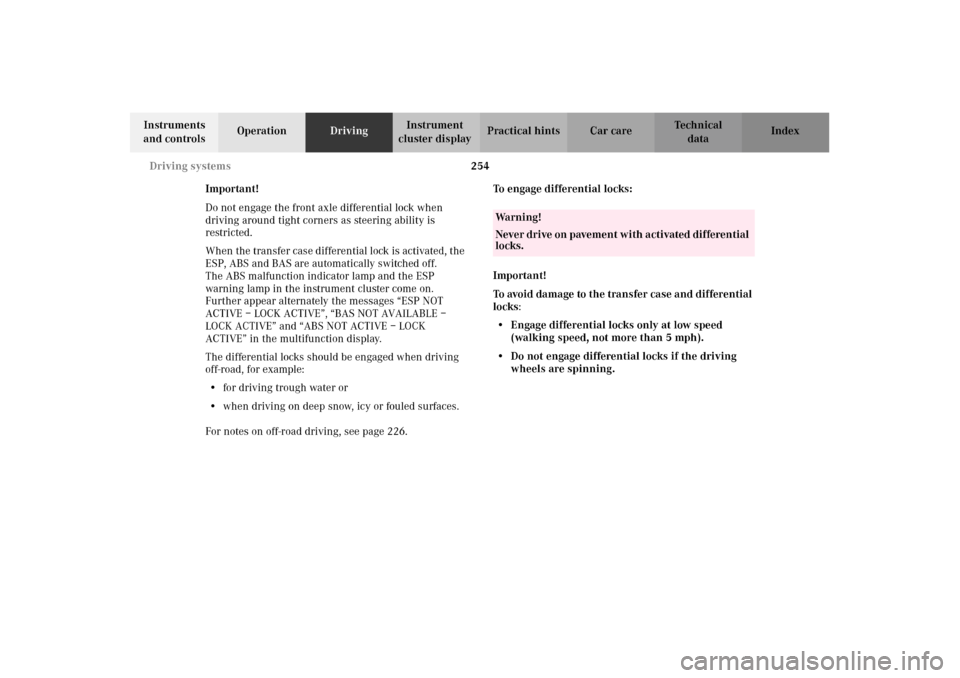
For notes on off-road driving, see page 226.To engage differential locks:
Important!
To avoid damage to the transfer case and differential
locks:
• Engage differential locks only at low speed
(walking speed, not more than 5 mph).
• Do not engage differential locks if the driving
wheels are spinning.
Wa r n i n g !
Never drive on pavement with activated differential
locks.
J_G463.book Seite 254 Mittwoch, 19. September 2001 8:06 08
Page 290 of 385
287 Malfunction and warning messages
Te ch n i c a l
data Instruments
and controlsOperation DrivingInstrument
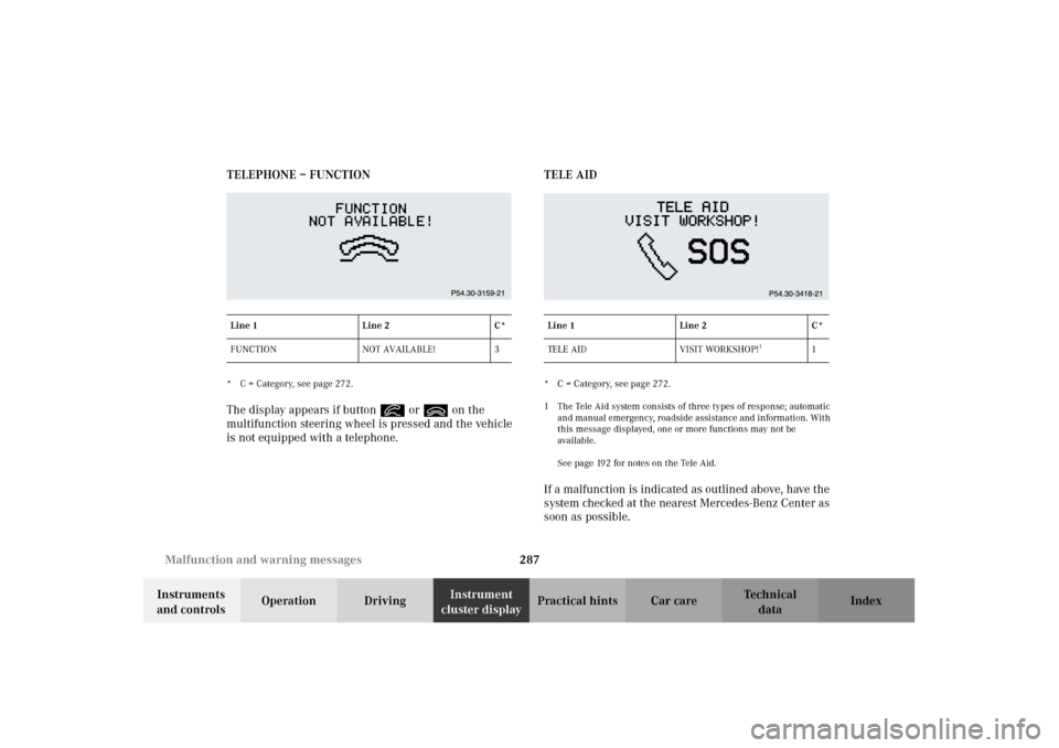
cluster displayPractical hints Car care Index TELEPHONE – FUNCTION
* C = Category, see page 272.The display appears if button í or ì on the
multifunction steering wheel is pressed and the vehicle
is not equipped with a telephone.TELE AID
* C = Category, see page 272.
1 The Tele Aid system consists of three types of response; automatic
and manual emergency, roadside assistance and information. With
this message displayed, one or more functions may not be
available.
See page 192 for notes on the Tele Aid.If a malfunction is indicated as outlined above, have the
system checked at the nearest Mercedes-Benz Center as
soon as possible.
Line 1 Line 2 C*
FUNCTION NOT AVAILABLE! 3
Line 1 Line 2 C*
TE L E A I D V I S I T WO R KS H O P !
1
1
J_G463.book Seite 287 Mittwoch, 19. September 2001 8:06 08
Page 298 of 385
295 Contents - Practical hints
Te ch n i c a l
data Instruments
and controlsOperation DrivingInstrument
cluster displayPractical hintsCar care Index
Practical hintsFirst aid kit, vehicle tools
and jack ......................................296
CD-changer .....................................296
Fuses ................................................297
Electrical outlet .............................. 301
Stowing items in the vehicle ........ 301
Hood .................................................302
Checking engine oil level .............304
Automatic transmission
fluid level ...................................305
Engine oil consumption ................305
Coolant level ...................................306
Adding coolant ...........................306
Windshield washer/headlamp
cleaning system .........................307
Windshield and headlamp
washer fluid mixing ratio .........307Vehicle jack .................................... 308
Wheels ............................................. 310
Tire replacement ........................ 310
Rotating wheels .......................... 311
Spare wheel cover ..........................312
Spare wheel ..................................... 313
Changing wheels ............................ 314
Tire inflation pressure .................. 318
Battery .............................................. 319
Jump starting ................................. 321
Towing the vehicle ........................ 324
Transmission selector lever,
manually unlocking .................. 327
Stranded vehicle ............................ 327
Exterior lamps ............................... 328
Headlamp assembly .................. 329
Fog lamp, front ........................... 332
Turn signal lamp, front ............ 334Turn signal lamp, side ...............335
Front and rear
side marker lamps .....................337
Taillamp assemblies ..................339
License plate lamp .....................340
Rear fog lamp / Backup lamp ... 341
Changing batteries in
the electronic key .....................343
Synchronizing
remote control ............................345
Emergency operation of
sliding/pop-up roof ...................346
Manual release for
fuel filler flap .............................347
Replacing wiper blades .................348
J_G463.book Seite 295 Mittwoch, 19. September 2001 8:06 08
Page 311 of 385
308 Spare wheel, vehicle jack
Te ch n i c a l
data Instruments
and controlsOperation DrivingInstrument
cluster displayPractical hintsCar care Index
Jack
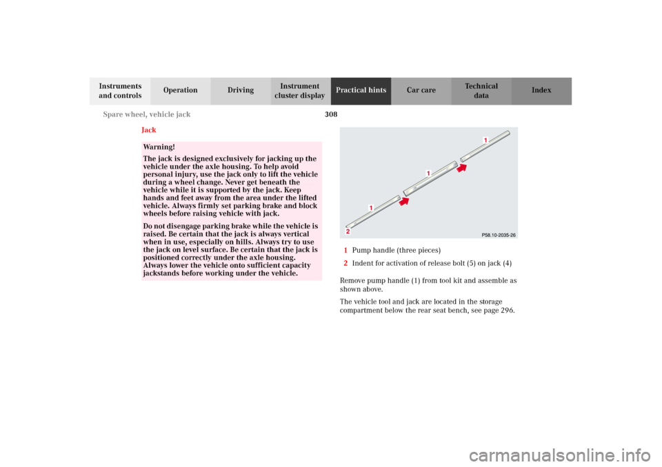
1Pump handle (three pieces)
2Indent for activation of release bolt (5) on jack (4)
Remove pump handle (1) from tool kit and assemble as
shown above.
The vehicle tool and jack are located in the storage
compartment below the rear seat bench, see page 296.
Wa r n i n g !
The jack is designed exclusively for jacking up the
vehicle under the axle housing. To help avoid
personal injury, use the jack only to lift the vehicle
during a wheel change. Never get beneath the
vehicle while it is supported by the jack. Keep
hands and feet away from the area under the lifted
vehicle. Always firmly set parking brake and block
wheels before raising vehicle with jack.Do n ot d is engage parki n g brake w hil e t he vehi c le i s
raised. Be certain that the jack is always vertical
when in use, especially on hills. Always try to use
the jack on level surface. Be certain that the jack is
positioned correctly under the axle housing.
Always lower the vehicle onto sufficient capacity
jackstands before working under the vehicle.
J_G463.book Seite 308 Mittwoch, 19. September 2001 8:06 08
Page 312 of 385
309 Spare wheel, vehicle jack
Te ch n i c a l
data Instruments
and controlsOperation DrivingInstrument
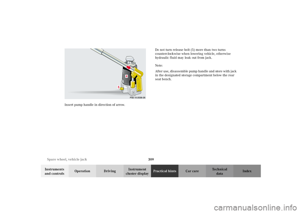
cluster displayPractical hintsCar care Index Insert pump handle in direction of arrow.Do not turn release bolt (5) more than two turns
counterclockwise when lowering vehicle, otherwise
hydraulic fluid may leak out from jack.
Note:
After use, disassemble pump handle and store with jack
in the designated storage compartment below the rear
seat bench.
J_G463.book Seite 309 Mittwoch, 19. September 2001 8:06 08
Page 313 of 385

310 Tires, Wheels
Te ch n i c a l
data Instruments
and controlsOperation DrivingInstrument
cluster displayPractical hintsCar care Index
Wheels
Replace rims or tires with the same designation,
manufacturer and type as shown on the original part.
See your authorized Mercedes-Benz Light Truck Center
for further information.
See your authorized Mercedes-Benz Light Truck Center
for information on tested and recommended rims and
tires for summer and winter operation. They can also
offer advice concerning tire service and purchase.Tire replacement
Front and rear tires should be replaced in sets. Rims
and tires must be of the correct size and type. For
dimensions, see technical data on page 359.
We recommend that you break in new tires for
approximately 60 miles (100 km) at moderate speed.
It is imperative that the wheel mounting bolts be
fastened to a tightening torque of 97 ft.lb. (130 Nm)
whenever wheels are mounted.
For rim and tire specif ications, refer to technical data on
page 359.
Wa r n i n g !
Do not mix different tire construction types (i.e.
radial, bias, bias-belted) on your vehicle because
handling may be adversely affected and may result
in loss of control.
Wa r n i n g !
Worn, old tires can cause accidents. If the tire tread
is badly worn, or if the tires have sustained
damage, replace them.When replacing rims, use only genuine
Mercedes-Benz wheel bolts specified for the
particular rim type. Failure to do so can result in
the bolts loosening and possibly an accident.
J_G463.book Seite 310 Mittwoch, 19. September 2001 8:06 08