2002 MAZDA 6 ignition
[x] Cancel search: ignitionPage 480 of 909

AUTOMATIC TRANSAXLE
K2–65
K2
Memory Function
•The memory function stores failure information detected in the failure detection function. Once failure
information is stored, the memory will not be cleared even when the ignition switch is turned off (LOCK
position) or the malfunction is repaired.
•The stored memory (failure information) can be cleared by using the WDS or disconnecting the negative
battery cable.
Failure Indication Function
•The failure indication function illuminates the AT warning lights when the failure detection function determines
there is a malfunction.
DTC Table
X : Available
CCM:Continuous monitor
Fail-safe Function
•In the fail-safe function, minimum vehicle drivability is obtained by changing the signals that are determined as
malfunctions by the failure detection function to the preset values, and limiting the TCM control.
DTC No. On-board diagnostic function MILAT warning
light
indicationDCMonitor
itemMemory
function
P0705 TR switch circuit malfunction (Power short circuit) X X 2 CCM X
P0706 TR switch circuit malfunction (Open/ground short circuit) X X 2 CCM X
P0711 TFT sensor malfunction (Stuck) X–2 CCM X
P0712 TFT sensor circuit malfunction (Short circuit) X X 2 CCM X
P0713 TFT sensor circuit malfunction (Open circuit) X X 2 CCM X
P0715 Input/turbine speed sensor circuit malfunction X X 2 CCM X
P0720 Vehicle speedometer sensor circuit malfunction X X 2 CCM X
P0740 TCC system X–2 CCM X
P0743 TCC solenoid valve malfunction (Open/short) X X 1 CCM X
P0748 Pressure control solenoid malfunction (Open/short)–X–CCM X
P0751 Shift solenoid A malfunction (Stuck off) X–2 CCM X
P0752 Shift solenoid A malfunction (Stuck on) X–2 CCM X
P0753 Shift solenoid A malfunction (Open/short) X X 1 CCM X
P0756 Shift solenoid B malfunction (Stuck off) X–2 CCM X
P0757 Shift solenoid B malfunction (Stuck on) X–2 CCM X
P0758 Shift solenoid B malfunction (Open/short) X X 1 CCM X
P0761 Shift solenoid C malfunction (Stuck off) X–2 CCM X
P0762 Shift solenoid C malfunction (Stuck on) X–2 CCM X
P0763 Shift solenoid C malfunction (Open/short) X X 1 CCM X
P0768 Reduction timing solenoid malfunction (Open/short)–X–CCM X
P0773 Neutral shift solenoid malfunction (Open/short)–X–CCM X
P0778 2-4 brake solenoid malfunction (Open/short)–X–CCM X
P0791 Intermediate sensor malfunction (Open/short) X X 2 CCM X
P0798 High clutch solenoid malfunction (Open/short)–X–CCM X
P1710 GND return malfunction–––Other X
U0073 CAN BUS OFF X X 1 CCM X
U0100 TCM cannot receive any signals from PCM X X 1 CCM X
DTC
No.On-board diagnostic function Detection condition Fail-safe TCC
P0705Transaxle range (TR) switch
circuit malfunction (power short
circuit)•Two or more range signals
are inputted from TR switch
for 5 seconds or more•TR switch priority
D > N > P > R
•Inhibits feedback control,
SLOPE mode, torque
reduction controlAvailable
P0706Transaxle range (TR) switch
circuit malfunction (open/ground
short circuit)•No range signal is inputted
from TR switch for 100
seconds or more•Inhibits feedback control,
SLOPE mode, torque
reduction controlAvailable
Page 487 of 909

K2–72
AUTOMATIC TRANSAXLE
MECHANICAL SYSTEM TESTA6E571401030209Mechanical System Test Preparation
1. Apply the parking brake and use wheel chocks at the front and rear of the wheels.
2. Inspect the engine coolant. (See Section E.)
3. Inspect the engine oil. (See D–8 ENGINE OIL INSPECTION.)
4. Inspect the ATF levels. (See K2–79 Automatic Transaxle Fluid (ATF) Level Inspection.)
5. Inspect the idle speed and ignition timing in P position. (See F1–22 IDLE SPEED INSPECTION (4WD).)
Line Pressure Test
Note
•Line pressure cannot be measured on the JA5AX-EL automatic transaxle. Measure the low clutch
pressure in place of D and M range line pressures. Measure the reverse clutch pressure in place of R
position line pressure.
1. Engine idling.
(1) Perform mechanical system test preparation. (See K2–72 Mechanical System Test Preparation.)
Warning
•Removing the plug when the ATF is hot can be dangerous. Hot ATF can come out of the opening
and badly burn you. Before removing the square-head plug, allow the ATF to cool.
(2) Remove the plug and O-ring shown in the
figure.
AUTOMATIC TRANSAXLE
LINE PRESSURE INSPECTION PORT
D,M RANGES
FRONT
A6E5714W101
LINE PRESSURE INSPECTION PORT
R POSITION
FRONT
A6E5714W102
Page 490 of 909

AUTOMATIC TRANSAXLE
K2–75
K2
Time Lag Test
1. Perform mechanical system test preparation. (See K2–72 Mechanical System Test Preparation.)
2. Start the engine.
3. Warm up the engine until the ATF temperature reaches 60—70°C {140—158°F}. Shift the selector lever from N
position to D range.
4. Use a stopwatch to measure the time it takes from shifting until engagement is felt. Take three measurements
for each test and average the results using the following formula.
Formula
Average time lag = (Time 1 + Time 2 + Time 3) / 3
5. Perform the test for the following shifts in the same manner.
•N position → P position
Time lag
N → D range ... approx. 0.5—1.0 second
N → R position ... approx. 0.6— 1.0 second
Evaluation of time lag test
End Of SieROAD TESTA6E571401030210Road Test Preparation
1. Inspect the engine coolant. (See Section E.)
2. Inspect the engine oil. (See D–8 ENGINE OIL INSPECTION.)
3. Inspect the ATF levels. (See K2–78 AUTOMATIC TRANSAXLE FLUID (ATF) INSPECTION.)
4. Inspect the idle speed and ignition timing in P position. (See F1–22 IDLE SPEED INSPECTION (4WD).)
5. Bring up the engine and transaxle to normal operating temperature.
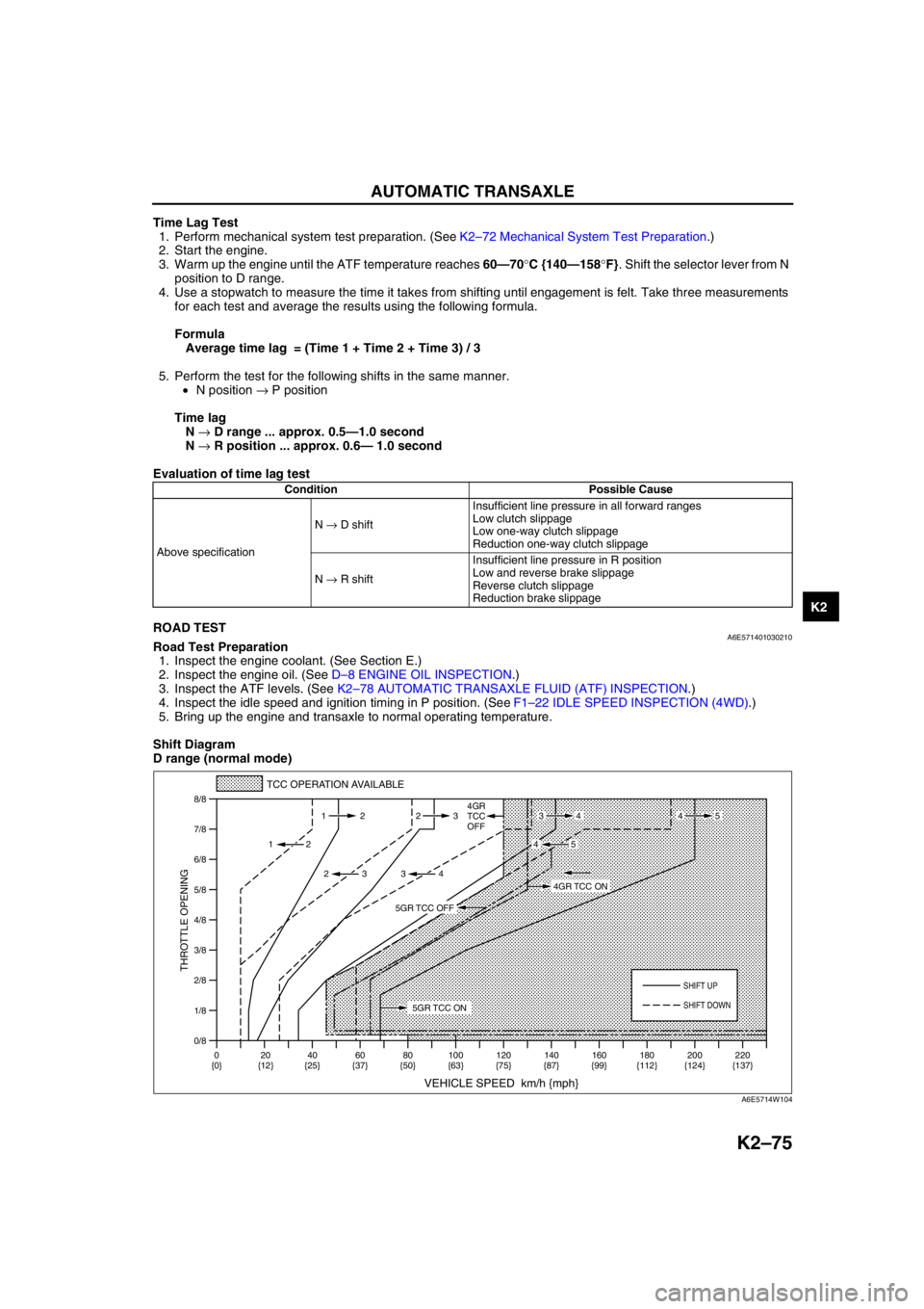
Shift Diagram
D range (normal mode)
Condition Possible Cause
Above specificationN → D shiftInsufficient line pressure in all forward ranges
Low clutch slippage
Low one-way clutch slippage
Reduction one-way clutch slippage
N → R shiftInsufficient line pressure in R position
Low and reverse brake slippage
Reverse clutch slippage
Reduction brake slippage
0/8 1/8
2/8
3/8
4/8
5/8
6/8
7/8
8/8
TCC OPERATION AVAILABLE
VEHICLE SPEED km/h {mph}
THROTTLE OPENING
SHIFT UP
4GR
TCC
OFF
SHIFT DOWN
0
{0}20
{12}40
{25}60
{37}80
{50}100
{63}120
{75}140
{87}160
{99}180
{112}220
{137} 200
{124} 112 23
2
2 232
34
4534
45
5GR TCC ON
4GR TCC ON
5GR TCC OFF
A6E5714W104
Page 495 of 909

K2–80
AUTOMATIC TRANSAXLE
AUTOMATIC TRANSAXLE FLUID (ATF) REPLACEMENTA6E571419001202
Warning
•When the transaxle and ATF are hot, they can badly burn you. Turn off the engine and wait until
they are cool before changing the ATF.
1. Remove the oil dipstick.
2. Remove the oil drain plug and washer.
3. Drain the ATF into a container.
4. Install a new washer and the drain plug.
Tightening torque
39—54 N·m {3.9—5.6 kgf·m, 29—40 ft·lbf}
5. Add the specified type of ATF through the oil filler
tube, until ATF level reaches lower notch of
dipstick.
ATF type
ATF M-III or equivalent (e.g. Dexron
®III)
Capacity (Approximate quantity)
8.3 L {8.8 US qt, 7.3 Imp qt}
6. Verify that the ATF level is in the HOT (65 °C {149 °F}) range.
•Add ATF to the specified level as necessary.
End Of Sie
TRANSAXLE RANGE (TR) SWITCH INSPECTIONA6E571419440201
Note
•Input signals of the TR switch can be inspected with a WDS or equivalent. (See K2–90 TCM
INSPECTION.)
Inspection of Operation
1. Verify that the starter operates only with the ignition switch at the START position and the selector lever in P
and N positions.
•If not as specified, inspect for continuity at the TR switch. (See K2–80 Inspection of Continuity.)
2. Verify that the back-up lights illuminate when shifted to R position with the ignition switch at the ON position.
•If not as specified, inspect for continuity at the TR switch.
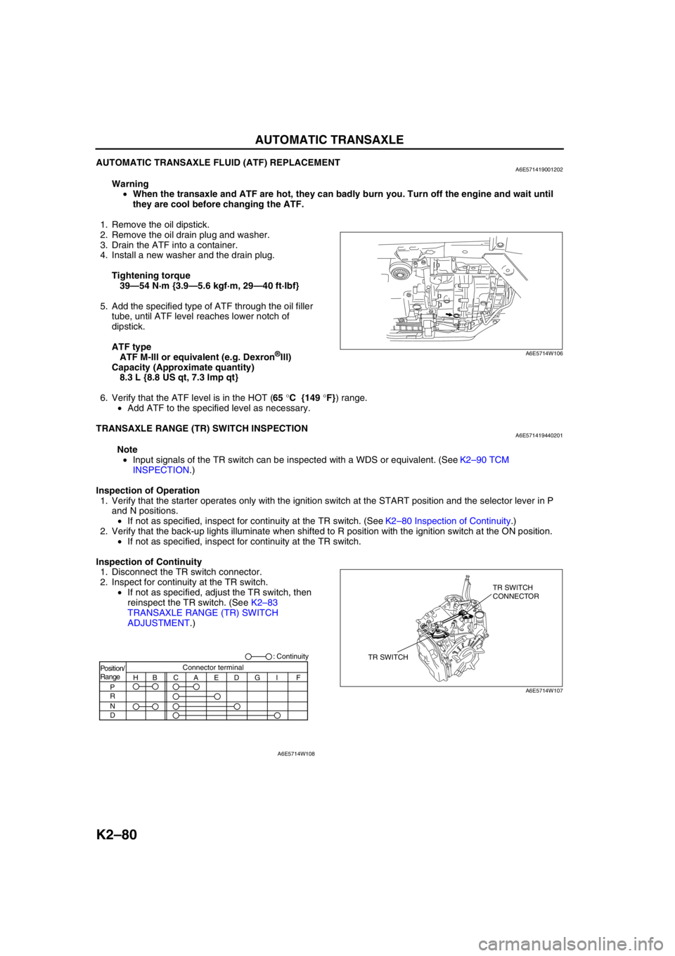
Inspection of Continuity
1. Disconnect the TR switch connector.
2. Inspect for continuity at the TR switch.
•If not as specified, adjust the TR switch, then
reinspect the TR switch. (See K2–83
TRANSAXLE RANGE (TR) SWITCH
ADJUSTMENT.)
A6E5714W106
TR SWITCHTR SWITCH
CONNECTOR
A6E5714W107
Position/
Range
H
P
R
N
DBCAEDGI FConnector terminal: Continuity
A6E5714W108
Page 509 of 909

K2–94
AUTOMATIC TRANSAXLE
Inspection Using An Oscilloscope (Reference)
Input/turbine speed sensor signal
•TCM terminal: 1N (+)—2F (–)
•Oscilloscope setting: 1 V/DIV (Y) 1 ms/DIV (X)
•Measuring condition: Turbine speed at 700 rpm,
N position
Intermediate sensor signal
•TCM terminal: 1K (+)—1X (–)
•Oscilloscope setting: 4 V/DIV (Y) 0.2 ms/DIV (X)
•Measuring condition: Vehicle speed at 40 km/h
{25 mph}, 4GR
Vehicle speedometer sensor signal
•TCM terminal: 1M (+)—1V (–)
•Oscilloscope setting: 4 V/DIV (Y) 1 ms/DIV (X)
•Measuring condition: Vehicle speed at 40 km/h
{25 mph}
2Y Pressure control
solenoid controlPressure control
solenoidN position B+•Inspect pressure control
solenoid
(See K2–88 SOLENOID
VALVE INSPECTION)
•Inspect related harness D position stall 0
2Z Power supply Main relay Ignition switch ON B+•Inspect main relay
(See T–19 Relay Type)
•Inspect related harness Ignition switch OFF 0
2AA Power supply Main relay Ignition switch ON B+•Inspect main relay
(See T–19 Relay Type)
•Inspect related harness Ignition switch OFF 0 Terminal Signal Connected to Test Condition Voltage (V) Action
AMU0517W045
AMU0517W046
AMU0517W047
Page 532 of 909

AUTOMATIC TRANSAXLE SHIFT MECHANISM
K2–117
K2
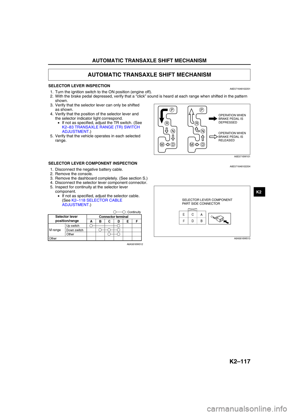
SELECTOR LEVER INSPECTIONA6E5716461022011. Turn the ignition switch to the ON position (engine off).
2. With the brake pedal depressed, verify that a “click” sound is heard at each range when shifted in the pattern
shown.
3. Verify that the selector lever can only be shifted
as shown.
4. Verify that the position of the selector lever and
the selector indicator light correspond.
•If not as specified, adjust the TR switch. (See
K2–83 TRANSAXLE RANGE (TR) SWITCH
ADJUSTMENT.)
5. Verify that the vehicle operates in each selected
range.
End Of SieSELECTOR LEVER COMPONENT INSPECTIONA6E5716461022041. Disconnect the negative battery cable.
2. Remove the console.
3. Remove the dashboard completely. (See section S.)
4. Disconnect the selector lever component connector.
5. Inspect for continuity at the selector lever
component.
•If not as specified, adjust the selector cable.
(See K2–118 SELECTOR CABLE
ADJUSTMENT.)
End Of Sie
AUTOMATIC TRANSAXLE SHIFT MECHANISM
P
R
N
DM
P
R
N
DM
OPERATION WHEN
BRAKE PEDAL IS
DEPRESSED
OPERATION WHEN
BRAKE PEDAL IS
RELEASED
A6E5716W101
SELECTOR LEVER COMPONENT
PART SIDE CONNECTOR
A6A5616W013
A6A5616W012
Page 539 of 909

K2–124
ON-BOARD DIAGNOSTIC
AFTER REPAIR PROCEDUREA6E577018901203
Caution
•After repairing a malfunction, perform this procedure to verify that the malfunction has been
corrected.
•When this procedure is carried out, be sure to drive the vehicle at lawful speed and pay attention
to the other vehicles.
1. Connect the SST (WDS or equivalent) to the DLC-2.
2. Turn the ignition key to ON (engine OFF).
3. Select the clear code function and clear the DTC.
4. Perform the following trouble code inspections to ensure that the DTC has been resolved:
•For P0705
i. Start the engine.
ii. Warm up the engine to normal operating temperature.
iii. Depress the brake pedal, and shift the selector lever between P to D for 5 seconds or more.
iv. Go to Step 5.
•For P0706
i. Start the engine.
ii. Warm up the engine to normal operating temperature.
iii. Depress the brake pedal, and shift the selector lever between P to D for 100 seconds or more.
iv. Go to Step 5.
•For P0711
i. Decrease ATF temperature to 20 °C {68 °F} or below.
ii. Start the engine.
iii. Drive the vehicle in D range for 10 minutes or more.
iv. Go to Step 5
•For P0712
i. Start the engine.
ii. Warm up the engine to normal operating temperature.
iii. Drive the vehicle in D range for 20 seconds or more.
iv. Go to Step 5.
•For P0713
i. Start the engine.
ii. Warm up the engine to normal operating temperature.
iii. Drive the vehicle in D range at 20 km/h {12mph} or above for 300 seconds or more.
iv. Go to Step 5.
•For P0715; P0791
i. Start the engine.
ii. Drive the vehicle under the following conditions for 2 seconds or more.
—Vehicle speed (VSS PID): 40 km/h {25 mph} or above
—Engine speed (RPM PID): 1,500 rpm or above.
—Selector lever position: D range
iii. Repeat Step ii again.
iv. Turn the IG switch to OFF.
v. Start the engine.
vi. Drive vehicle under the following conditions for 2 second or more.
—Vehicle speed (VSS PID): 40 km/h {25 mph} or above
—Engine speed (RPM PID): 1,500 rpm or above.
—Selector lever position: D range
vii. Go to Step 5.
•For P0720
i. Start the engine.
ii. Warm up the engine and ATX.
iii. Drive vehicle under the following conditions for 2 seconds or more.
—Selector lever position: D range
—Vehicle speed (VSS PID): 40 km/h {25 mph}
—Engine speed (RPM PID): 1,500 rpm or above.
iv. Go to Step 5.
Page 543 of 909

K2–128
ON-BOARD DIAGNOSTIC
End Of Sie
3VERIFY CURRENT INPUT SIGNAL STATUS-IS
CONCERN INTERMITTENT OR CONSTANT?
•Connect volt meter to TCM.
•Turn ignition key to ON (engine OFF).
•Inspect TCM terminal voltages.
(See K2–90 TCM INSPECTION.)
—TCM terminal 2B
•P position: B+
•Other positions and all ranges: 0V
—TCM terminal 1W
•R position: B+
•Other positions and all ranges: 0V
—TCM terminal 1T
—N position: B+
—Other positions and all ranges: 0V
—TCM terminal 1Z
•D range: B+
•Other ranges and all positions: 0V
•Are two or more of following terminal voltage at
the same time when shifting selector lever from
P position to D range?Yes Go to next step.
No Go to intermittent concern troubleshooting procedure.
(See section F1.)
4INSPECT TR SWITCH CONNECTOR
•Turn ignition key OFF.
•Disconnect TR switch connector.
•Inspect bent terminals of pins using mirror.
•Are TR switch terminals okay?Yes Go to next step.
No Repair terminals or replace TR switch, then go to Step 8.
(See K2–81 TRANSAXLE RANGE (TR) SWITCH
REMOVAL/INSTALLATION.)
5INSPECT TR SWITCH CIRCUIT MALFUNCTION
•Connect voltmeter to TCM.
•Turn ignition key to ON (engine OFF).
•Does TCM terminal voltage change from B+ to
0V when TR switch connector is disconnected?Yes Go to next step.
No Go to Step 7.
6INSPECT TR SWITCH CONTINUITY
•Turn ignition key to OFF.
•Disconnect TR switch connector.
•Inspect TR switch for continuity in positions/
ranges failed in Step 4.
•Is there continuity between TR switch terminals
(part side)?
(See K2–80 TRANSAXLE RANGE (TR) SWITCH
INSPECTION.)Yes Go to Step 8.
No Replace TR switch, then go to Step 8.
(See K2–81 TRANSAXLE RANGE (TR) SWITCH
REMOVAL/INSTALLATION.)
7INSPECT TR SWITCH CIRCUIT FOR SHORT TO
POWER
•Turn ignition key to ON (engine OFF).
•Measure voltage at TR switch terminal A, E, D,
G, I, and F (harness-side).
•Is there 0 V at TR switch harness side
connector?Yes Go to next step.
No Repair or replace wiring, then go to next step.
8VERIFY TROUBLESHOOTING OF DTC P0705
COMPLETED
•Make sure to reconnect all disconnected
connectors.
•Clear DTC from memory using WDS or
equivalent.
•Turn ignition key to on (engine off).
•Drive vehicle in each range (P, R, N, and D) for
5 seconds or more.
•Is same DTC present?Yes Replace TCM, then go to next step.
(See K2–96 TCM REMOVAL/INSTALLATION.)
No Go to next step.
9VERIFY AFTER REPAIR PROCEDURE
•Perform “After Repair Procedure”.
(See K2–124 AFTER REPAIR PROCEDURE.)
•Is there any DTC present?Yes Go to applicable DTC inspection.
No Troubleshooting completed. STEP INSPECTION ACTION