Page 190 of 909

F2–38
INTAKE-AIR SYSTEM
TURBOCHARGER INSPECTIONA6E401013700201
Note
•If the following problems exist, diagnosis the turbocharger using the following symptom troubleshooting
procedures.
1. Lack of power: perform “NO.12 LACK/LOSS OF POWER”. (See F2–195 NO.12 LACK/LOSS OF POWER-
ACCELERATION/CRUISE.)
2. Oil leak: perform “NO.16 HIGH OIL CONSUMPTION/LEAKAGE”. (See F2–209 NO.16 HIGH OIL
CONSUMPTION/LEAKAGE.)
3. Noise: perform “NO. 21 ENGINE NOISE”. (See F2–217 NO.21 ENGINE NOISE.)
Compressor Wheel Inspection
1. Remove the air pipe between the air cleaner and the turbocharger. (See F2–36 INTAKE-AIR SYSTEM
REMOVAL/INSTALLATION.)
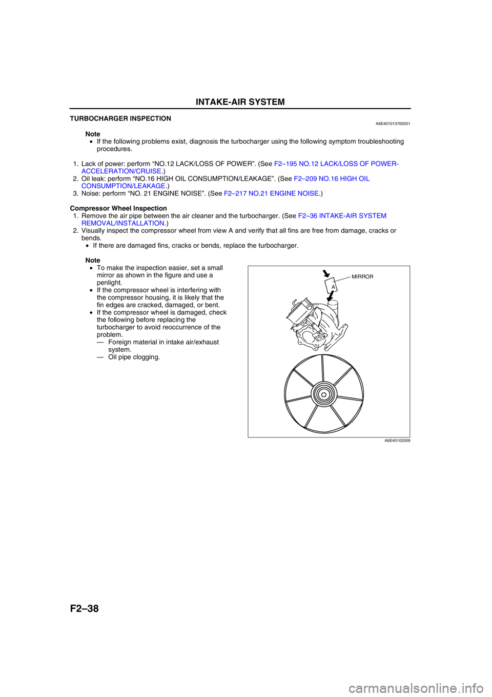
2. Visually inspect the compressor wheel from view A and verify that all fins are free from damage, cracks or
bends.
•If there are damaged fins, cracks or bends, replace the turbocharger.
Note
•To make the inspection easier, set a small
mirror as shown in the figure and use a
penlight.
•If the compressor wheel is interfering with
the compressor housing, it is likely that the
fin edges are cracked, damaged, or bent.
•If the compressor wheel is damaged, check
the following before replacing the
turbocharger to avoid reoccurrence of the
problem.
—Foreign material in intake air/exhaust
system.
—Oil pipe clogging.
MIRROR
A
A6E40102009
Page 191 of 909

INTAKE-AIR SYSTEM
F2–39
F2
Turbine Wheel Inspection
1. Remove the warm up oxidation catalytic converter between the flexible pipe and the turbocharger. (See F2–57
EXHAUST SYSTEM REMOVAL/INSTALLATION.)
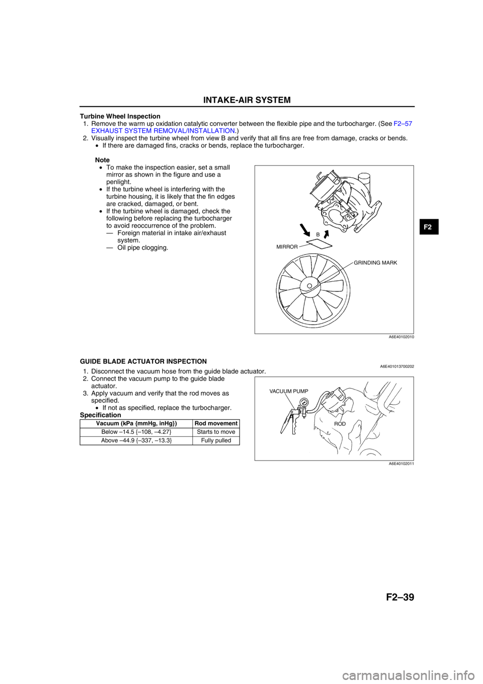
2. Visually inspect the turbine wheel from view B and verify that all fins are free from damage, cracks or bends.
•If there are damaged fins, cracks or bends, replace the turbocharger.
Note
•To make the inspection easier, set a small
mirror as shown in the figure and use a
penlight.
•If the turbine wheel is interfering with the
turbine housing, it is likely that the fin edges
are cracked, damaged, or bent.
•If the turbine wheel is damaged, check the
following before replacing the turbocharger
to avoid reoccurrence of the problem.
—Foreign material in intake air/exhaust
system.
—Oil pipe clogging.
End Of Sie
GUIDE BLADE ACTUATOR INSPECTIONA6E4010137002021. Disconnect the vacuum hose from the guide blade actuator.
2. Connect the vacuum pump to the guide blade
actuator.
3. Apply vacuum and verify that the rod moves as
specified.
•If not as specified, replace the turbocharger.
Specification
End Of Sie
MIRRORB
GRINDING MARK
A6E40102010
Vacuum (kPa {mmHg, inHg}) Rod movement
Below –14.5 {–108, –4.27} Starts to move
Above –44.9 {–337, –13.3} Fully pulled
VACUUM PUMP
ROD
A6E40102011
Page 543 of 909

K2–128
ON-BOARD DIAGNOSTIC
End Of Sie
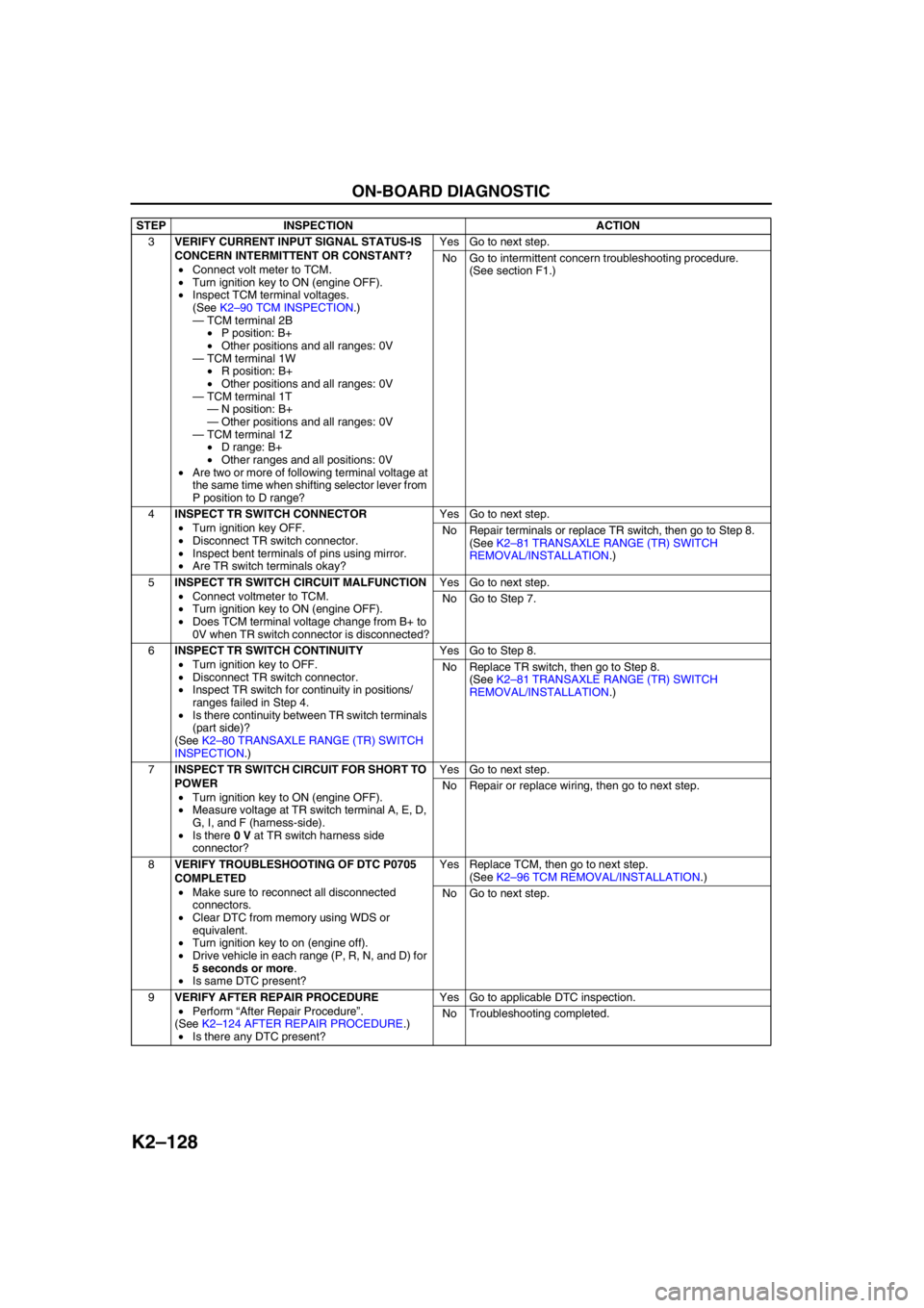
3VERIFY CURRENT INPUT SIGNAL STATUS-IS
CONCERN INTERMITTENT OR CONSTANT?
•Connect volt meter to TCM.
•Turn ignition key to ON (engine OFF).
•Inspect TCM terminal voltages.
(See K2–90 TCM INSPECTION.)
—TCM terminal 2B
•P position: B+
•Other positions and all ranges: 0V
—TCM terminal 1W
•R position: B+
•Other positions and all ranges: 0V
—TCM terminal 1T
—N position: B+
—Other positions and all ranges: 0V
—TCM terminal 1Z
•D range: B+
•Other ranges and all positions: 0V
•Are two or more of following terminal voltage at
the same time when shifting selector lever from
P position to D range?Yes Go to next step.
No Go to intermittent concern troubleshooting procedure.
(See section F1.)
4INSPECT TR SWITCH CONNECTOR
•Turn ignition key OFF.
•Disconnect TR switch connector.
•Inspect bent terminals of pins using mirror.
•Are TR switch terminals okay?Yes Go to next step.
No Repair terminals or replace TR switch, then go to Step 8.
(See K2–81 TRANSAXLE RANGE (TR) SWITCH
REMOVAL/INSTALLATION.)
5INSPECT TR SWITCH CIRCUIT MALFUNCTION
•Connect voltmeter to TCM.
•Turn ignition key to ON (engine OFF).
•Does TCM terminal voltage change from B+ to
0V when TR switch connector is disconnected?Yes Go to next step.
No Go to Step 7.
6INSPECT TR SWITCH CONTINUITY
•Turn ignition key to OFF.
•Disconnect TR switch connector.
•Inspect TR switch for continuity in positions/
ranges failed in Step 4.
•Is there continuity between TR switch terminals
(part side)?
(See K2–80 TRANSAXLE RANGE (TR) SWITCH
INSPECTION.)Yes Go to Step 8.
No Replace TR switch, then go to Step 8.
(See K2–81 TRANSAXLE RANGE (TR) SWITCH
REMOVAL/INSTALLATION.)
7INSPECT TR SWITCH CIRCUIT FOR SHORT TO
POWER
•Turn ignition key to ON (engine OFF).
•Measure voltage at TR switch terminal A, E, D,
G, I, and F (harness-side).
•Is there 0 V at TR switch harness side
connector?Yes Go to next step.
No Repair or replace wiring, then go to next step.
8VERIFY TROUBLESHOOTING OF DTC P0705
COMPLETED
•Make sure to reconnect all disconnected
connectors.
•Clear DTC from memory using WDS or
equivalent.
•Turn ignition key to on (engine off).
•Drive vehicle in each range (P, R, N, and D) for
5 seconds or more.
•Is same DTC present?Yes Replace TCM, then go to next step.
(See K2–96 TCM REMOVAL/INSTALLATION.)
No Go to next step.
9VERIFY AFTER REPAIR PROCEDURE
•Perform “After Repair Procedure”.
(See K2–124 AFTER REPAIR PROCEDURE.)
•Is there any DTC present?Yes Go to applicable DTC inspection.
No Troubleshooting completed. STEP INSPECTION ACTION