2002 MAZDA 6 oil level
[x] Cancel search: oil levelPage 406 of 909

J2–4
MANUAL TRANSAXLE
TRANSAXLE OIL INSPECTIONA6E5212270012011. Park the vehicle on level ground.
2. Remove the filler plug and gasket.
3. Verify that the oil is near the brim of the plug port.
•If the oil level is low, add the specified amount
and type of oil through the filler plug hole.
Specified oil grade
API Service GL-4 or GL-5
Specified oil viscosity
SAE 75W-90
4. Install a new gasket and the filler plug.
Tightening torque
30.0—39.0 N·m
{3.06—3.98 kgf·m, 22.1—28.8 in·lbf}
End Of Sie
TRANSAXLE OIL REPLACEMENTA6E5212270012021. Remove the drain plug with the gasket.
2. Drain the oil into a suitable container.
3. Install a new gasket and the drain plug.
Tightening torque
30.0—39.0 N·m
{3.06—3.98 kgf·m, 22.1—28.8 in·lbf}
4. Remove the filler plug with gasket and add the
specified amount and type of oil through the filler
plug hole until the level reaches the bottom of the
filler plug hole.
Specified oil grade
API Service GL-4 or GL-5
Specified oil viscosity
SAE 75W-90
Capacity (approximate quantity)
2.30 L {2.40 US qt, 2.00 lmp qt}
5. Install a new gasket and the filler plug.
Tightening torque
30.0—39.0 N·m
{3.06—3.98 kgf·m, 22.1—28.8 in·lbf}
End Of Sie
MANUAL TRANSAXLE
DRAIN PLUG FILLER PLUG
A6E5212W010
DRAIN PLUG FILLER PLUG
A6E5212W010
Page 407 of 909

MANUAL TRANSAXLE
J2–5
J2
OIL SEAL (DIFFERENTIAL) REPLACEMENTA6E5212192402011. On level ground, jack up the vehicle and support it evenly on safety stands.
2. Drain the oil from the transaxle.
3. Remove the front wheels and splash shields.
4. Separate the drive shaft and joint shaft from the transaxle. (See Section M.)
5. Remove the oil seals using a screwdriver.
6. Using the SSTs and a hammer, tap each new oil
seal in evenly until the SSTs contact the transaxle
case.
7. Coat the lip of each oil seal with transaxle oil.
8. Insert the drive shaft and joint shaft into the
transaxle. (See Section M.)
9. Install the wheels and splash shields.
10. Add the specified amount and type of oil. (See
J2–4 TRANSAXLE OIL REPLACEMENT.)
End Of SieREVERSE SWITCH INSPECTIONA6E5212190102011. Disconnect the reverse switch connector.
2. Shift the shift lever to each position, and inspect
for continuity between terminals A and B.
•If not as specified, replace the reverse switch.
(See J2–6 REVERSE SWITCH REMOVAL/
INSTALLATION.)
3. Connect the reverse switch connector.
End Of Sie
AME5212W005
49 G030 797
49 U027 003
A6E5212W011
REVERSE SWITCH
A6E5212W012
BA REVERSE SWITCH
PART SIDE CONNENTOR
A6E5212W013
Shift positionConnector terminal
AB:
Continuity
Reverse
Others
A6E5212W014
Page 409 of 909

MANUAL TRANSAXLE
J2–7
J2
NEUTRAL SWITCH REMOVAL/INSTALLATIONA6E5212190102041. Remove the neutral switch.
2. Apply a light coat of silicone sealant to the screw
of the neutral switch.
Sealant
Three Bond product: TB1215
3. Install the neutral switch to the transaxle case.
Tightening torque
22.5—33.3 N·m
{2.29—3.40 kgf·m, 16.6—24.6 ft·lbf}
End Of Sie
MANUAL TRANSAXLE REMOVAL/INSTALLATIONA6E5212010292011. Remove the battery and battery tray.
2. Remove the air cleaner compornent. (See F2–36 INTAKE-AIR SYSTEM REMOVAL/INSTALLATION.)
3. Remove the air hose above the transaxle. (See F2–36 INTAKE-AIR SYSTEM REMOVAL/INSTALLATION.)
4. Remove the air pipe above the transaxle. (See F2–36 INTAKE-AIR SYSTEM REMOVAL/INSTALLATION.)
5. Remove the solenoid bracket.
6. Remove the wheels, tires and splash shields.
7. Remove the under cover.
8. Separate the steering hose.
9. Remove the steering gear and linkage, and pipe assembly installation bolts from the front crossmember, then
suspend the steering gear and linkage with a cable. (See N–8 STEERING GEAR AND LINKAGE (MZR-CD
(RF Turbo)) REMOVAL/INSTALLATION.)
Tightening torque
•Pipe assembly: 7.8—10.8 N·m {79.6—110.0 kgf·cm, 69.1—95.5 in·lbf}
10. Remove the front auto leveling sensor. (See Section T.)
11. Drain the transaxle oil into a suitable container.
12. Remove in the order indicated in the table.
13. Install in the reverse order of removal.
14. Adjust the headlight zeroset. (See Section T.)
15. Add the specified amount of specified transaxle oil. (See J2–4 TRANSAXLE OIL REPLACEMENT.)
16. Warm up the engine and transaxle, inspect for oil leakage, and inspect the transaxle operation.
NEUTRAL
SWITCH
A6E5212W015
Page 487 of 909

K2–72
AUTOMATIC TRANSAXLE
MECHANICAL SYSTEM TESTA6E571401030209Mechanical System Test Preparation
1. Apply the parking brake and use wheel chocks at the front and rear of the wheels.
2. Inspect the engine coolant. (See Section E.)
3. Inspect the engine oil. (See D–8 ENGINE OIL INSPECTION.)
4. Inspect the ATF levels. (See K2–79 Automatic Transaxle Fluid (ATF) Level Inspection.)
5. Inspect the idle speed and ignition timing in P position. (See F1–22 IDLE SPEED INSPECTION (4WD).)
Line Pressure Test
Note
•Line pressure cannot be measured on the JA5AX-EL automatic transaxle. Measure the low clutch
pressure in place of D and M range line pressures. Measure the reverse clutch pressure in place of R
position line pressure.
1. Engine idling.
(1) Perform mechanical system test preparation. (See K2–72 Mechanical System Test Preparation.)
Warning
•Removing the plug when the ATF is hot can be dangerous. Hot ATF can come out of the opening
and badly burn you. Before removing the square-head plug, allow the ATF to cool.
(2) Remove the plug and O-ring shown in the
figure.
AUTOMATIC TRANSAXLE
LINE PRESSURE INSPECTION PORT
D,M RANGES
FRONT
A6E5714W101
LINE PRESSURE INSPECTION PORT
R POSITION
FRONT
A6E5714W102
Page 490 of 909

AUTOMATIC TRANSAXLE
K2–75
K2
Time Lag Test
1. Perform mechanical system test preparation. (See K2–72 Mechanical System Test Preparation.)
2. Start the engine.
3. Warm up the engine until the ATF temperature reaches 60—70°C {140—158°F}. Shift the selector lever from N
position to D range.
4. Use a stopwatch to measure the time it takes from shifting until engagement is felt. Take three measurements
for each test and average the results using the following formula.
Formula
Average time lag = (Time 1 + Time 2 + Time 3) / 3
5. Perform the test for the following shifts in the same manner.
•N position → P position
Time lag
N → D range ... approx. 0.5—1.0 second
N → R position ... approx. 0.6— 1.0 second
Evaluation of time lag test
End Of SieROAD TESTA6E571401030210Road Test Preparation
1. Inspect the engine coolant. (See Section E.)
2. Inspect the engine oil. (See D–8 ENGINE OIL INSPECTION.)
3. Inspect the ATF levels. (See K2–78 AUTOMATIC TRANSAXLE FLUID (ATF) INSPECTION.)
4. Inspect the idle speed and ignition timing in P position. (See F1–22 IDLE SPEED INSPECTION (4WD).)
5. Bring up the engine and transaxle to normal operating temperature.
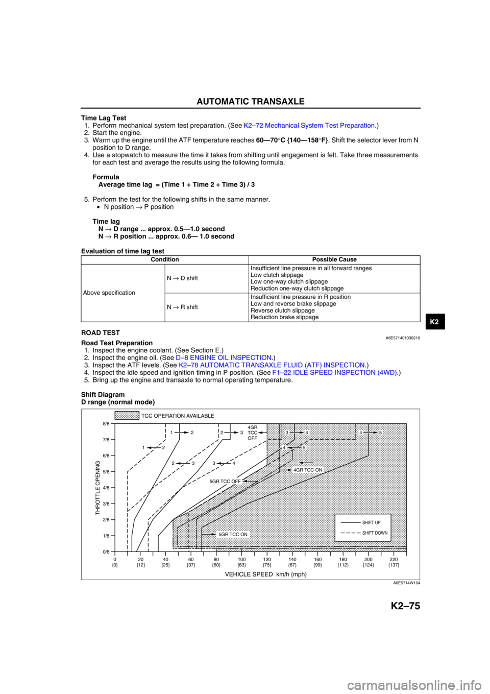
Shift Diagram
D range (normal mode)
Condition Possible Cause
Above specificationN → D shiftInsufficient line pressure in all forward ranges
Low clutch slippage
Low one-way clutch slippage
Reduction one-way clutch slippage
N → R shiftInsufficient line pressure in R position
Low and reverse brake slippage
Reverse clutch slippage
Reduction brake slippage
0/8 1/8
2/8
3/8
4/8
5/8
6/8
7/8
8/8
TCC OPERATION AVAILABLE
VEHICLE SPEED km/h {mph}
THROTTLE OPENING
SHIFT UP
4GR
TCC
OFF
SHIFT DOWN
0
{0}20
{12}40
{25}60
{37}80
{50}100
{63}120
{75}140
{87}160
{99}180
{112}220
{137} 200
{124} 112 23
2
2 232
34
4534
45
5GR TCC ON
4GR TCC ON
5GR TCC OFF
A6E5714W104
Page 494 of 909

AUTOMATIC TRANSAXLE
K2–79
K2
Automatic Transaxle Fluid (ATF) Level Inspection
Caution
•The ATF amount varies according to ATF's temperature. Therefore, when checking the ATF level or
replacing the ATF, use a thermometer to measure the temperature then adjust the ATF amount to
the specified level according to the specified temperature.
1. Park the vehicle on level ground.
2. Apply the parking brake and position wheel chocks securely to prevent the vehicle from rolling.
3. Adjust the length of the thermistor probe measure to the measure same as the dipstick and hold the probe with
a paper holder.
4. Insert into the filler tube and measure the
temperature.
5. Warm up the engine until the ATF reaches (60—
70 °C {140—158 °F}).
Caution
•Do not warm the transaxle by performing
stalls. This will damage the torque
converter.
Note
•In some cases it may be necessary to
inspect the ATF in the cool range 15—25 °C
{59—77 °F} before warming up the engine.
6. While depressing the brake pedal, shift the selector lever to each range (P—M), pausing momentarily in each
range.
7. Shift back to P position.
Note
•If the ATF level is too high or too low in hot condition, the following problems may be the cause.
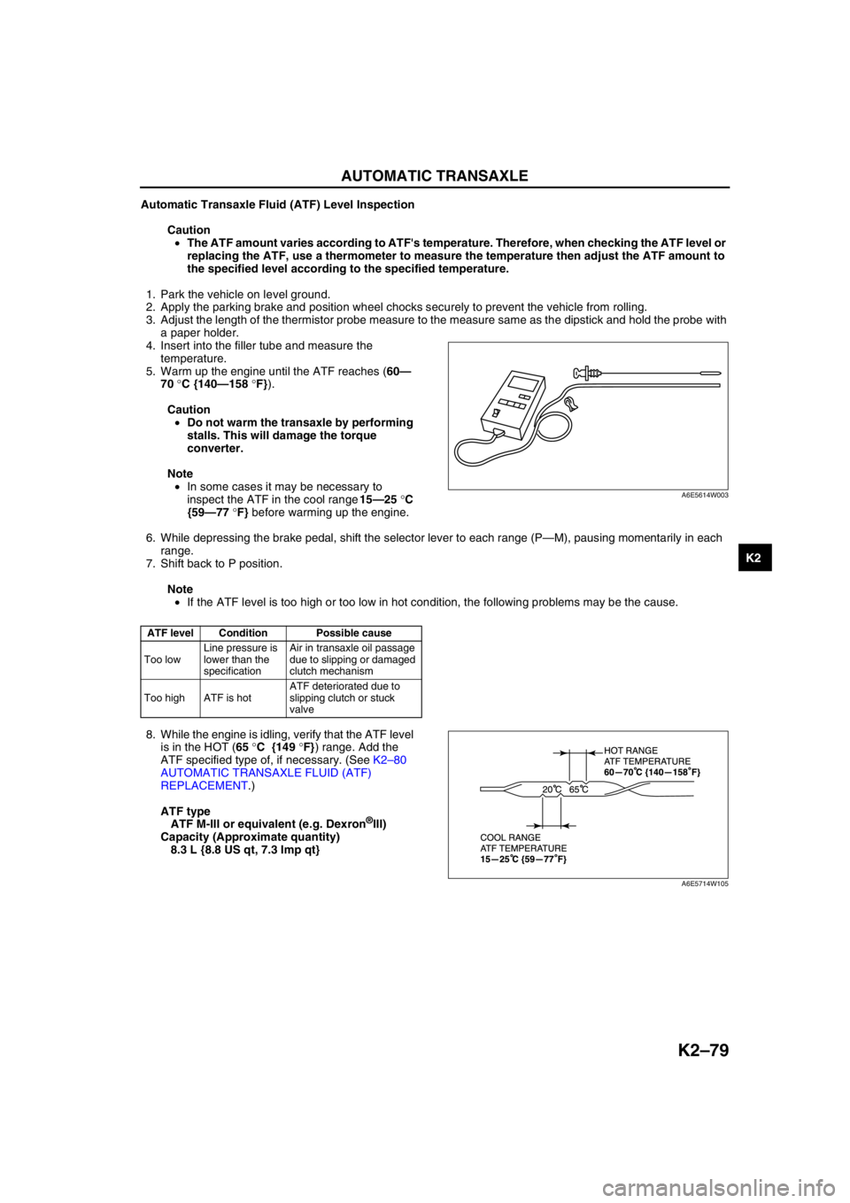
8. While the engine is idling, verify that the ATF level
is in the HOT (65 °C {149 °F}) range. Add the
ATF specified type of, if necessary. (See K2–80
AUTOMATIC TRANSAXLE FLUID (ATF)
REPLACEMENT.)
ATF type
ATF M-III or equivalent (e.g. Dexron
®III)
Capacity (Approximate quantity)
8.3 L {8.8 US qt, 7.3 Imp qt}
End Of Sie
ATF level Condition Possible cause
Too lowLine pressure is
lower than the
specificationAir in transaxle oil passage
due to slipping or damaged
clutch mechanism
Too high ATF is hotATF deteriorated due to
slipping clutch or stuck
valve
A6E5614W003
A6E5714W105
Page 495 of 909

K2–80
AUTOMATIC TRANSAXLE
AUTOMATIC TRANSAXLE FLUID (ATF) REPLACEMENTA6E571419001202
Warning
•When the transaxle and ATF are hot, they can badly burn you. Turn off the engine and wait until
they are cool before changing the ATF.
1. Remove the oil dipstick.
2. Remove the oil drain plug and washer.
3. Drain the ATF into a container.
4. Install a new washer and the drain plug.
Tightening torque
39—54 N·m {3.9—5.6 kgf·m, 29—40 ft·lbf}
5. Add the specified type of ATF through the oil filler
tube, until ATF level reaches lower notch of
dipstick.
ATF type
ATF M-III or equivalent (e.g. Dexron
®III)
Capacity (Approximate quantity)
8.3 L {8.8 US qt, 7.3 Imp qt}
6. Verify that the ATF level is in the HOT (65 °C {149 °F}) range.
•Add ATF to the specified level as necessary.
End Of Sie
TRANSAXLE RANGE (TR) SWITCH INSPECTIONA6E571419440201
Note
•Input signals of the TR switch can be inspected with a WDS or equivalent. (See K2–90 TCM
INSPECTION.)
Inspection of Operation
1. Verify that the starter operates only with the ignition switch at the START position and the selector lever in P
and N positions.
•If not as specified, inspect for continuity at the TR switch. (See K2–80 Inspection of Continuity.)
2. Verify that the back-up lights illuminate when shifted to R position with the ignition switch at the ON position.
•If not as specified, inspect for continuity at the TR switch.
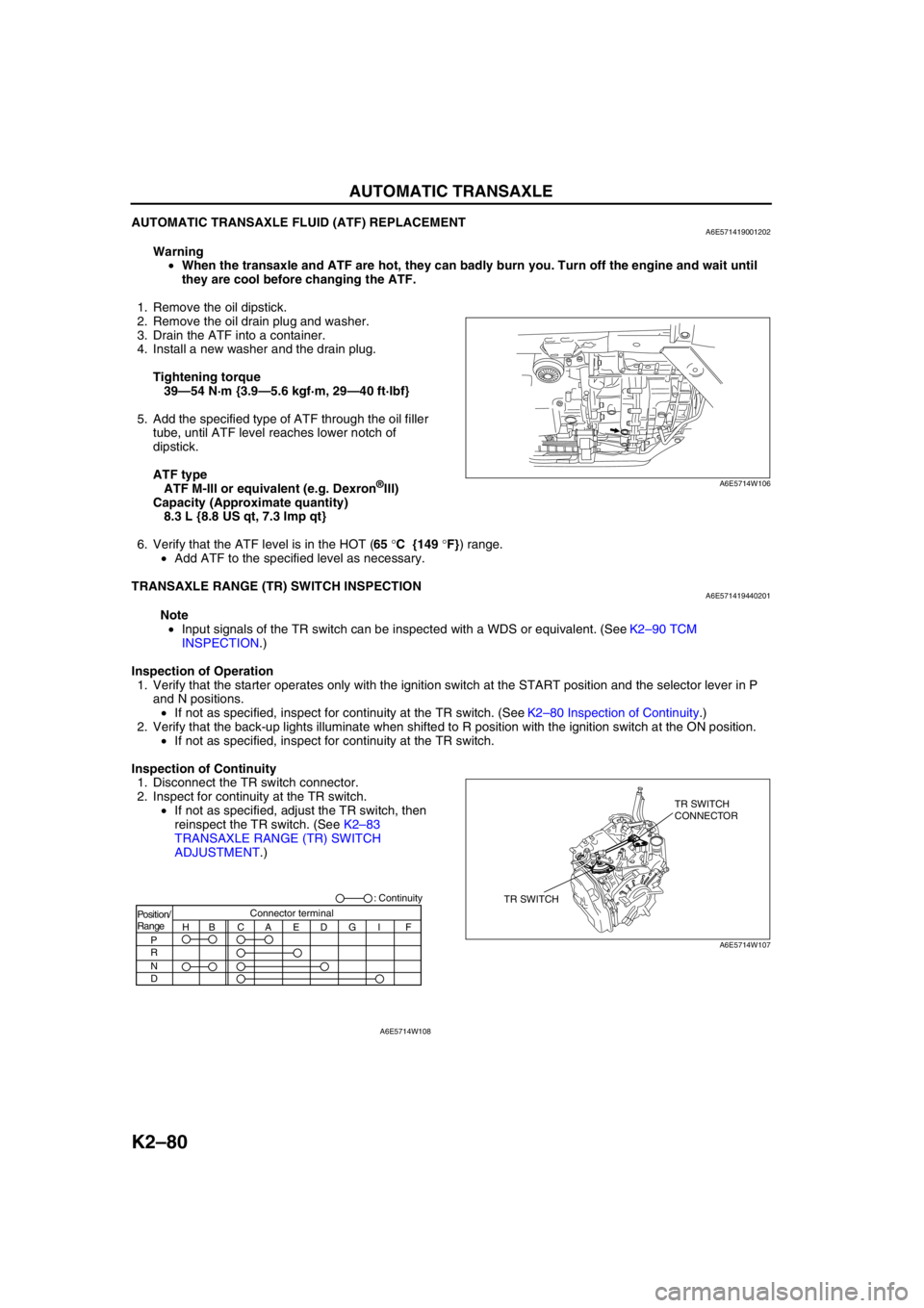
Inspection of Continuity
1. Disconnect the TR switch connector.
2. Inspect for continuity at the TR switch.
•If not as specified, adjust the TR switch, then
reinspect the TR switch. (See K2–83
TRANSAXLE RANGE (TR) SWITCH
ADJUSTMENT.)
A6E5714W106
TR SWITCHTR SWITCH
CONNECTOR
A6E5714W107
Position/
Range
H
P
R
N
DBCAEDGI FConnector terminal: Continuity
A6E5714W108
Page 514 of 909

AUTOMATIC TRANSAXLE
K2–99
K2
AUTOMATIC TRANSAXLE AND TRANSFER REMOVAL/INSTALLATIONA6E5714190902011. Disconnect the negative battery cable.
2. Remove the battery and battery tray.
3. Remove the aircleaner component. (See Sectin F.)
4. Remove the front tires and splash shield.
5. Remove the under cover.
6. Separate the steering shaft and steering hose. (See N–13 STEERING GEAR AND LINKAGE (4WD)
REMOVAL/INSTALLATION.)
7. Remove the front auto leveling sensor. (See Section T.)
8. Drain the ATF. (See K2–80 AUTOMATIC TRANSAXLE FLUID (ATF) REPLACEMENT.)
Warning
•Improperly jacking a transaxle is dangerous. It can slip off the jack and may cause serious injury.
Caution
•To prevent the torque converter and transaxle from separating, remove the transaxle without
tilting it toward the torque converter.
9. Remove in the order shown in the figure.
10. Install in the reverse order of removal.
11. Adjust the headlight zeroset. (See Section T.)
12. Add ATF to the specified level. (See K2–80 AUTOMATIC TRANSAXLE FLUID (ATF) REPLACEMENT.)
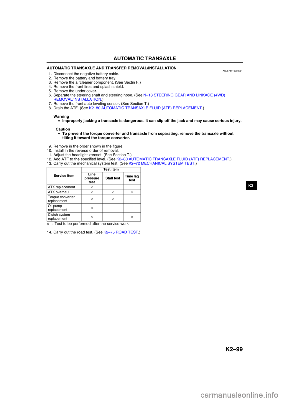
13. Carry out the mechanical system test. (See K2–72 MECHANICAL SYSTEM TEST.)
×: Test to be performed after the service work
14. Carry out the road test. (See K2–75 ROAD TEST.)
Service itemTest item
Line
pressure
testStall testTime lag
test
ATX replacement×
ATX overhaul×××
Torque converter
replacement××
Oil pump
replacement×
Clutch system
replacement××