Page 58 of 909

ENGINE
B2–27
B2
ENGINE REMOVAL/INSTALLATIONA6E232401001201
Warning
•Fuel vapor is hazardous. It can very easily ignite, causing serious injury and damage. Always keep
sparks and flames away from fuel.
•Fuel line spills and leakage are dangerous. Fuel can ignite and cause serious injures or death and
damage. Fuel can also irritate skin and eyes. To prevent this, always complete the “Fuel Line
Safety Procedure”. (See F2–45 Fuel Line Safety Procedures.)
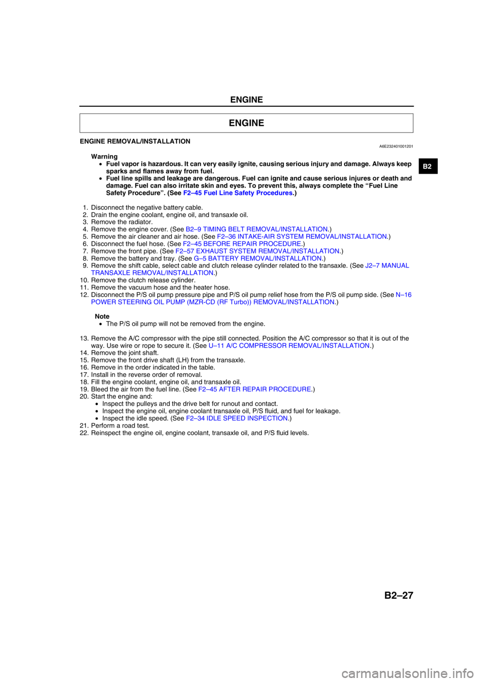
1. Disconnect the negative battery cable.
2. Drain the engine coolant, engine oil, and transaxle oil.
3. Remove the radiator.
4. Remove the engine cover. (See B2–9 TIMING BELT REMOVAL/INSTALLATION.)
5. Remove the air cleaner and air hose. (See F2–36 INTAKE-AIR SYSTEM REMOVAL/INSTALLATION.)
6. Disconnect the fuel hose. (See F2–45 BEFORE REPAIR PROCEDURE.)
7. Remove the front pipe. (See F2–57 EXHAUST SYSTEM REMOVAL/INSTALLATION.)
8. Remove the battery and tray. (See G–5 BATTERY REMOVAL/INSTALLATION.)
9. Remove the shift cable, select cable and clutch release cylinder related to the transaxle. (See J2–7 MANUAL
TRANSAXLE REMOVAL/INSTALLATION.)
10. Remove the clutch release cylinder.
11. Remove the vacuum hose and the heater hose.
12. Disconnect the P/S oil pump pressure pipe and P/S oil pump relief hose from the P/S oil pump side. (See N–16
POWER STEERING OIL PUMP (MZR-CD (RF Turbo)) REMOVAL/INSTALLATION.)
Note
•The P/S oil pump will not be removed from the engine.
13. Remove the A/C compressor with the pipe still connected. Position the A/C compressor so that it is out of the
way. Use wire or rope to secure it. (See U–11 A/C COMPRESSOR REMOVAL/INSTALLATION.)
14. Remove the joint shaft.
15. Remove the front drive shaft (LH) from the transaxle.
16. Remove in the order indicated in the table.
17. Install in the reverse order of removal.
18. Fill the engine coolant, engine oil, and transaxle oil.
19. Bleed the air from the fuel line. (See F2–45 AFTER REPAIR PROCEDURE.)
20. Start the engine and:
•Inspect the pulleys and the drive belt for runout and contact.
•Inspect the engine oil, engine coolant transaxle oil, P/S fluid, and fuel for leakage.
•Inspect the idle speed. (See F2–34 IDLE SPEED INSPECTION.)
21. Perform a road test.
22. Reinspect the engine oil, engine coolant, transaxle oil, and P/S fluid levels.
ENGINE
Page 60 of 909
ENGINE
B2–29
B2
No.1 Engine Mount Rubber Removal Note
1. Suspend the engine using the SST.
2. Remove through-bolt A on the No.1 engine mount
bracket side.
3. Loosen through-bolt B on the front crossmember
side until approximately three pitches are
showing.
Note
•Do not remove the No.1 engine mount
rubber from the front crossmember.
No.4 Engine Mount Bracket and No.4 Engine Mount Rubber Removal Note
1. Secure the engine and the transaxle using an
engine jack and attachment as shown.
49 E017 5A0
A6E2316W101
A B
A6E2324W201
A6E2324W202
A6E2324W209
Page 61 of 909
B2–30
ENGINE
2. Remove the SST.
3. Secure the engine and the transaxle using a
hoist.
4. Remove the No.4 engine mount bracket and
engine mount rubber together as a unit.
No.3 Engine Joint Bracket Installation Note
1. Tighten the No.3 engine mount bracket stud bolt.
Tightening torque
7.0—13 N·m {71.4—132.5 kgf·cm,
62.0—115.0 in·lbf}49 E017 5A0
A6E2316W101
A6E2324W203
A6E2324W304
No.3 ENGINE
MOUNT
BRACKET
STUD
BOLT
A6E2316W200
Page 62 of 909
ENGINE
B2–31
B2
2. Tighten the No.3 engine joint bracket bolt and nut
in the order as shown.
Tightening torque
74.5—104.9 N·m {7.6—10.6 kgf·m,
55.0—76.6 ft·lbf}
No.4 Engine Mount Bracket and No.4 Engine Mount Rubber Installation Note
1. Tighten the No.4 engine mount bracket and No.4
engine mount rubber bolt and nut in the order as
shown.
2. Secure the engine and the transaxle using an
engine jack and attachment as shown.
3. Remove the hoist and secure the engine and
transaxle using SST.12
A6E2316W111
Bolt or nut No.Tightening torque
(N·m {kgf·m, ft·lbf})
1, 2, 358.8—80.4 {6.0—8.1, 43.3—58.5}
4, 5, 666.6—93.1 {6.8—9.4, 49.2—67.9}
5431
2
6
A6E2324W306
A6E2324W209
49 E017 5A0
A6E2316W101
Page 72 of 909

D–8
ENGINE OIL
ENGINE OIL INSPECTIONA6E331214001201MZR-CD (RF Turbo)
1. Position the vehicle on level ground.
2. Warm up the engine to normal operating temperature.
3. Stop the engine and wait for 5 min.
4. Verify that the oil level is between the L and F marks on the dipstick and check the engine oil condition.
•If the oil level is below the L mark, add engine oil. (See D–8 ENGINE OIL REPLACEMENT.)
End Of SieENGINE OIL REPLACEMENTA6E331214001202MZR-CD (RF Turbo)
Warning
•Hot engines and engine oil can cause severe burns. Turn off the engine and wait until it and the
engine oil have cooled.
•A vehicle that is lifted but not securely supported on safety stands is dangerous. It can slip or fall,
causing death or serious injury. Never work around or under a lifted vehicle if it is not securely
supported on safety stands.
•Continuous exposure to USED engine oil has caused skin cancer in laboratory mice. Protect your
skin by washing with soap and water immediately after working with engine oil.
Caution
•In case you spill engine oil on the front pipe, wipe it off completely. If you fail to wipe the spilled
oil, it will produce fumes because of the heat.
1. Position the vehicle on level ground.
2. Remove the the oil filler cap.
3. Remove the under cover.
4. Remove the oil pan drain plug.
5. Drain the engine oil into a container.
6. Install the oil pan drain plug with a new the washer.
Tightening torque
12—17 N·m {1.2—1.8 kgf·m, 9—13 ft·lbf}
Note
•The amount of residual oil in the engine can vary with the replacement method, oil temperature, etc. Verify
the oil level after engine oil replacement.
7. Refill the engine oil with the specified type and amount, then install the oil filler cap.
Oil capacity (approximate quantity)
L {US qt, Imp qt}
Note
•The maintenance intervals on scheduled maintenance table (See GI–8 SCHEDULED MAINTENANCE
TABLE) can only be supported with the use of following oils.
Recommended Engine Oil
8. Start the engine and inspect for oil leakage.
•If the oil leaks, specify the faulty part and repair or replace it.
9. Inspect the oil level .
•If the necessary, add oil. (See D–8 ENGINE OIL INSPECTION.)
10. Install the under cover.
End Of Sie
ENGINE OIL
Item Specification
Total (dry engine) 5.5 {5.8, 4.8}
Oil replacement 4.8 {5.1, 4.2}
Oil and oil filter replacement 5.0 {5.3, 4.4}
Item Specification
Engine oil GradeAPI CF CD, CE, CF-4
ACEA B1 or B3 B3 B3 or B4
Viscosity (SAE) 5W-30 10W-40 5W-30, 10W-30
RemarksMazda genuine Dexelia oil e.g. —
Page 93 of 909
OUTLINE
F1–5
F1
11 Knock sensor
12 CKP sensor
13 CMP sensor
14 Fuel injector No.1
15 Fuel injector No.2
16 Fuel injector No.3
17 Fuel injector No.4
18 IAC valve
19 Oxygen sensor heater (front)
20 Oxygen sensor heater (rear)
21 A/C relay22 Cooling fan relay
23 Cooling fan relay
24 Cooling fan relay
25 TR switch
26 Fuel pump relay
27 Coil
28 Security light
29 Ignition switch
30 Main relay
31 TR switch
32 Starter relay
Page 116 of 909

F1–28
FUEL SYSTEM
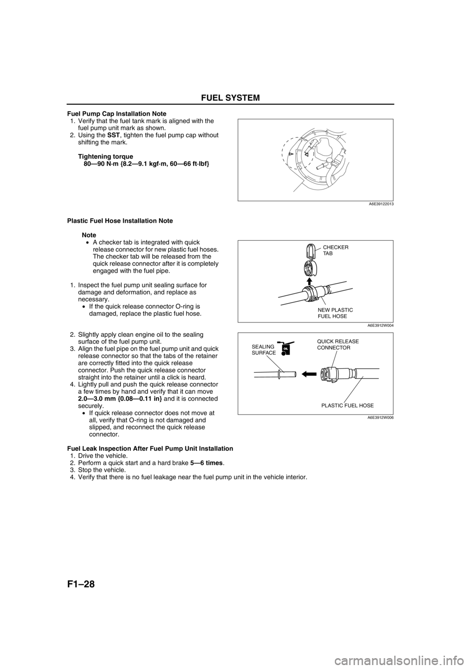
Fuel Pump Cap Installation Note
1. Verify that the fuel tank mark is aligned with the
fuel pump unit mark as shown.
2. Using the SST, tighten the fuel pump cap without
shifting the mark.
Tightening torque
80—90 N·m {8.2—9.1 kgf·m, 60—66 ft·lbf}
Plastic Fuel Hose Installation Note
Note
•A checker tab is integrated with quick
release connector for new plastic fuel hoses.
The checker tab will be released from the
quick release connector after it is completely
engaged with the fuel pipe.
1. Inspect the fuel pump unit sealing surface for
damage and deformation, and replace as
necessary.
•If the quick release connector O-ring is
damaged, replace the plastic fuel hose.
2. Slightly apply clean engine oil to the sealing
surface of the fuel pump unit.
3. Align the fuel pipe on the fuel pump unit and quick
release connector so that the tabs of the retainer
are correctly fitted into the quick release
connector. Push the quick release connector
straight into the retainer until a click is heard.
4. Lightly pull and push the quick release connector
a few times by hand and verify that it can move
2.0—3.0 mm {0.08—0.11 in} and it is connected
securely.
•If quick release connector does not move at
all, verify that O-ring is not damaged and
slipped, and reconnect the quick release
connector.
Fuel Leak Inspection After Fuel Pump Unit Installation
1. Drive the vehicle.
2. Perform a quick start and a hard brake 5—6 times.
3. Stop the vehicle.
4. Verify that there is no fuel leakage near the fuel pump unit in the vehicle interior.
End Of Sie
A6E39122013
CHECKER
TA B
NEW PLASTIC
FUEL HOSE
A6E3912W004
OILOIL
PLASTIC FUEL HOSE QUICK RELEASE
CONNECTOR SEALING
SURFACE
A6E3912W006
Page 117 of 909

FUEL SYSTEM
F1–29
F1
FUEL HOSE (FUEL TANK SIDE, TRANSFER HOSE PART) REMOVAL/INSTALLATIONA6E391242692202
Warning
•Repairing a fuel tank that has not been properly steam cleaned can be dangerous. Explosion or
fire may cause death or serious injury. Always properly steam clean a fuel tank before repairing it.
•Fuel line spills and leakage are dangerous. Fuel can ignite and cause serious injuries or death and
damage. Fuel can also irritate skin and eyes. To prevent this, do not damage the sealing surface of
the fuel pump unit when removing or installing.
Caution
•Disconnecting/connecting the quick release connector without cleaning it may possibly cause
damage to the fuel pipe and quick release connector. Always clean the quick release connector
joint area before disconnecting/connecting using a cloth or soft brush, and make sure that it is
free of foreign material.
Removal
1. Complete the “BEFORE REPAIR PROCEDURE”.
2. Disconnect the negative battery cable.
Note
•Squeezing the tab while lightly pushing the fuel hose on the fuel pipe side will make removal easier.
3. Squeeze the tabs on the quick release connector
and disconnect the quick release connector from
the fuel pipe by pulling it straight back.
4. Cover the disconnected quick release connector
and fuel pipe with vinyl sheets or the like to
prevent them from being scratched or
contaminated with foreign material.
Installation
Caution
•If the quick release connector O-ring is damaged, replace the plastic fuel hose. A fuel leak may be
caused.
1. Inspect the fuel hose and fuel pipe sealing surface for damage and deformation, and replace as necessary.
2. Slightly apply clean engine oil to the sealing surface of the fuel pump unit.
3. Align the fuel pipe and quick release connector. Push the quick release connector straight into the fuel pipe
until a click is heard.
4. Lightly pull and push the quick release connector a few times by hand and verify that it can move 2.0—3.0 mm
{0.08—0.11 in} and it is connected securely.
•If the quick release connector does not move at all, verify that O-ring is not damaged and slipped, and
reconnect the quick release connector.
5. Complete the “AFTER REPAIR PROCEDURE”.
End Of Sie
QUICK RELEASE
CONNECTOR TA BDISCONNECT
FUEL PIPE
A6E39122007
A6E39122014