2002 LAND ROVER DISCOVERY ECU
[x] Cancel search: ECUPage 1433 of 1672
WIPERS AND WASHERS
84-12 DESCRIPTION AND OPERATION
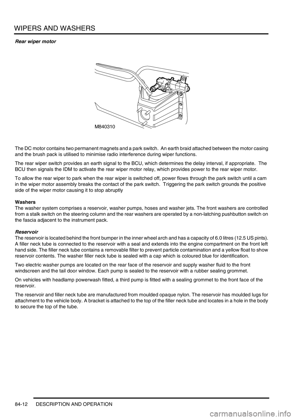
Rear wiper motor
The DC motor contains two permanent magnets and a park switch. An earth braid attached between the motor casing
and the brush pack is utilised to minimise radio interference during wiper functions.
The rear wiper switch provides an earth signal to the BCU, which determines the delay interval, if appropriate. The
BCU then signals the IDM to activate the rear wiper motor relay, which provides power to the rear wiper motor.
To allow the rear wiper to park when the rear wiper is switched off, power flows through the park switch until a cam
in the wiper motor assembly breaks the contact of the park switch. Triggering the park switch grounds the positive
side of the wiper motor causing it to stop abruptly
Washers
The washer system comprises a reservoir, washer pumps, hoses and washer jets. The front washers are controlled
from a stalk switch on the steering column and the rear washers are operated by a non-latching pushbutton switch on
the fascia adjacent to the instrument pack.
Reservoir
The reservoir is located behind the front bumper in the inner wheel arch and has a capacity of 6.0 litres (12.5 US pints).
A filler neck tube is connected to the reservoir with a seal and extends into the engine compartment on the front left
hand side. The filler neck tube contains a removable filter to prevent particle contamination and a yellow float to show
reservoir contents. The washer filler neck tube is sealed with a cap which is coloured blue for identification.
Two electric washer pumps are located on the rear face of the reservoir and supply washer fluid to the front
windscreen and the tail door window. Each pump is sealed to the reservoir with a rubber sealing grommet.
On vehicles with headlamp powerwash fitted, a third pump is fitted with a sealing grommet to the front face of the
reservoir.
The reservoir and filler neck tube are manufactured from moulded opaque nylon. The reservoir has moulded lugs for
attachment to the vehicle body. A bracket is attached to the top of the filler neck tube and locates in a hole in the body
to secure the top of the tube.
Page 1434 of 1672
WIPERS AND WASHERS
DESCRIPTION AND OPERATION 84-13
Front screen washer jets
Two washer jets for the front windscreen are fitted to the top surface of the bonnet and held in place with plastic clips.
Each washer jet is connected via a hose to an in-line valve. The in-line valve prevents the washer fluid draining back
to the reservoir and ensures that the washers operate immediately the washer pump is operated. From each in-line
valve the washers are connected via a short hose to a 'T' connector. From the 'T' connector a single hose connects
to the outlet of the front washer pump. Each jet has two jets which can be adjusted to allow full fluid coverage of the
windscreen.
Rear screen washer jet
A single washer jet for the tail door window is fitted to the rear wiper blade. The jet has four spray orifices which direct
washer fluid to either side and along the length of the wiper blade. The jet is connected by a hose from the wiper blade,
through a sealing grommet in the tail door and connects with the rear washer hose from the rear washer pump. A non-
return valve is used to join the feed hose from the pump to the washer jet hose. The non-return valve prevents fluid
draining to the reservoir and ensures that the washer operates immediately the washer pump is operated. The hose
from the pump to the tail door is located inside the main harness.
Headlamp power washer jets
When fitted, a powerwash jet for each headlamp is located in a housing on the top surface of the front bumper. The
jets are fed with fluid at high pressure from the powerwash pump. A large diameter hose connects each jet to the
pump. Each connection is secured with a metal clip to secure the hose due to the high pressure from the pump. Each
jet directs the high pressure fluid in a wide spray onto the headlamp lens.
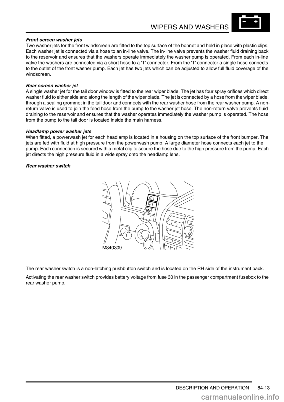
Rear washer switch
The rear washer switch is a non-latching pushbutton switch and is located on the RH side of the instrument pack.
Activating the rear washer switch provides battery voltage from fuse 30 in the passenger compartment fusebox to the
rear washer pump.
Page 1437 of 1672

WIPERS AND WASHERS
84-16 DESCRIPTION AND OPERATION
Operation
Front intermittent wipe variable delay
The front intermittent wipe variable delay operation allows the driver to adjust the interval between wipes to suit local
conditions. Front variable delay operation activates when the following conditions are met:
lIgnition switch in position I or II.
lFront wash/ wipe switch is in the intermittent position.
The BCU receives the front intermittent wipe signal from the front wash/ wipe switch. The BCU receives a separate
signal from the variable delay switch, determines the delay interval from the front wash/ wipe switch position and
passes it on to the IDM. The IDM energises the front wiper relay to activate the front wiper motor.
If the delay duration is decreased during front variable delay operation, the wipers immediately operate once and then
the delay cycle is reset to the new duration.
If the delay duration is increased during front variable delay operation, the delay cycle is automatically increased by
the BCU.
Front low speed
Front low-speed operation activates when the following conditions are met:
lIgnition switch is in position I or II.
lFront wipe/ wash switch is in low speed position.
Selecting low-speed on the front wash/ wipe switch signals the IDM to energises the front wiper relay, which provides
power to the front wiper motor assembly.
Front high speed
Front high-speed operation activates when the following conditions are met:
lIgnition switch is in position I or II.
lFront wipe/ wash switch is in high speed position.
Selecting high speed on the front wash/ wipe switch allows power to flow from the switch directly to the wiper motor.
The high-speed input goes to a set of brushes in the wiper motor that are closer together than the low speed brushes.
These brushes allow the motor to run at a faster speed but with less torque.
Front washer
Front washer operation will only activate when the following conditions are met:
lIgnition switch is in position I or II.
lFront washer switch operated.
Flicking the front washer switch energises the front washer pump motor for 0.4 second. Holding the front washer
switch for longer than 0.4 second allows the front washer pump motor to run as long as the switch is held.
There are two front washer configurations. If the vehicle is fitted with programme wash/ wipe, and the front washer
pump motor is active for more than 0.5 second, the front wipers operate at low speed. The wipers continue to operate
for 4 seconds after the washer switch is released. In some markets, the driver must activate the front wipers after a
front washer operation.
The front washer operation has a higher priority than the variable delay operation. This means that if intermittent wipe
is active when a front washer operation is initiated, the wash cycle executes and the intermittent wipe is re-instated
at the end of the wash operation.
Page 1439 of 1672

WIPERS AND WASHERS
84-18 DESCRIPTION AND OPERATION
Rear wipe
Rear wipe operation will only activate when the following conditions are met:
lIgnition switch is in position II.
lRear wipe switch is operated.
Operating the rear wiper switch provides an earth input to the BCU. The BCU tells the IDM to activate the rear wiper
relay, which provides battery voltage to the wiper motor through the normally closed contacts of the park switch.
Rear wash
Rear wash will only operate when the following conditions are met:
lIgnition switch is in position II.
lRear wash switch operated.
Operating the rear washer switch for longer than 0.4 second allows the rear washer pump motor and rear wipers to
run as long as the switch is held. The wipers run for 4 seconds after the rear washer switch is released. Flicking the
rear washer switch energises the rear washer pump motor for 0.4 second.
The rear washer operation has a higher priority than the intermittent wipe operation. If the intermittent wipe is active
when a rear washer operation is initiated, the wash cycle executes and the intermittent wipe is re-instated at the end
of the washer operation.
Wiper park switch
The park switch allows the wipers to come to rest in the park position when the wipe switch is turned off in mid-wipe.
The park switch consists of a positive and a negative contact. These two contacts are described as closed at park
and closed when operating. When the wipers first start, the park switch is in the closed at park position. A relay
controls battery voltage to the motor. Battery voltage passes through this relay contact to move the wiper motor from
the park position.
When the motor moves, the park switch moves to the closed when operating position. Battery voltage to this relay
contact is direct from fuse 19. Battery voltage passes through this contact to keep the wiper motor running. The wiper
motor operates for one complete revolution until the park switch moves to the closed at park position again.
Switching off the wipers removes battery voltage from the closed at park contact. When the wipers reach the closed
at park switch an earth is applied and the motor stops abruptly.
Headlamp power wash
Headlamp power wash activates when the following conditions are met:
lIgnition switch in position II.
lHeadlamps switched on.
lFront wash switch operated.
lBCU counter allows headlamp power wash.
Operating the front washer switch with the headlamps switched on energises the IDM, supplying a voltage to the
headlamp powerwash relay, which operates the headlamp powerwash pump and increments a counter within the
BCU. This counter prevents the headlamp powerwash pump from operating every time the front washer switch is
activated. Headlamp powerwash is only operational every third front wash cycle, providing the headlamps are on.
The counter resets when the ignition switch is turned off.
When the BCU permits headlamp power wash operation, the pump motor operates only for 0.5 second.
Page 1440 of 1672
WIPERS AND WASHERS
REPAIRS 84-19
REPAIRS
Reservoir - washer - up to 03MY
$% 84.10.03
Remove
1.Remove front grille.
+ EXTERIOR FITTINGS, REPAIRS,
Grille - front - up to 03MY.
2.Remove front bumper assembly.
+ EXTERIOR FITTINGS, REPAIRS,
Bumper assembly - front.
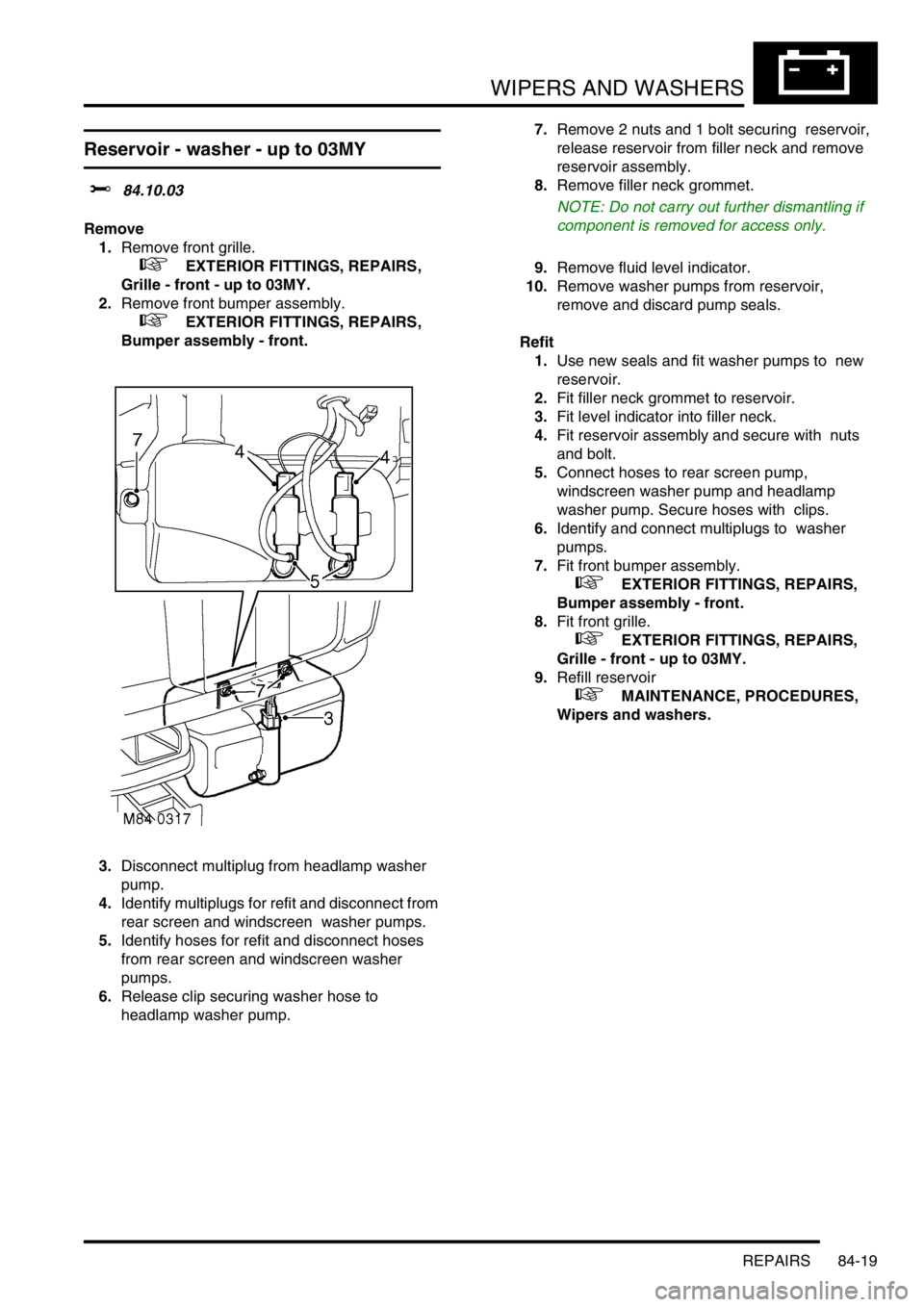
3.Disconnect multiplug from headlamp washer
pump.
4.Identify multiplugs for refit and disconnect from
rear screen and windscreen washer pumps.
5.Identify hoses for refit and disconnect hoses
from rear screen and windscreen washer
pumps.
6.Release clip securing washer hose to
headlamp washer pump. 7.Remove 2 nuts and 1 bolt securing reservoir,
release reservoir from filler neck and remove
reservoir assembly.
8.Remove filler neck grommet.
NOTE: Do not carry out further dismantling if
component is removed for access only.
9.Remove fluid level indicator.
10.Remove washer pumps from reservoir,
remove and discard pump seals.
Refit
1.Use new seals and fit washer pumps to new
reservoir.
2.Fit filler neck grommet to reservoir.
3.Fit level indicator into filler neck.
4.Fit reservoir assembly and secure with nuts
and bolt.
5.Connect hoses to rear screen pump,
windscreen washer pump and headlamp
washer pump. Secure hoses with clips.
6.Identify and connect multiplugs to washer
pumps.
7.Fit front bumper assembly.
+ EXTERIOR FITTINGS, REPAIRS,
Bumper assembly - front.
8.Fit front grille.
+ EXTERIOR FITTINGS, REPAIRS,
Grille - front - up to 03MY.
9.Refill reservoir
+ MAINTENANCE, PROCEDURES,
Wipers and washers.
Page 1441 of 1672
WIPERS AND WASHERS
84-20 REPAIRS
Reservoir - washer - from 03MY
$% 84.10.03
Remove
1.Remove the front bumper assembly.
+ EXTERIOR FITTINGS, REPAIRS,
Bumper assembly - front.
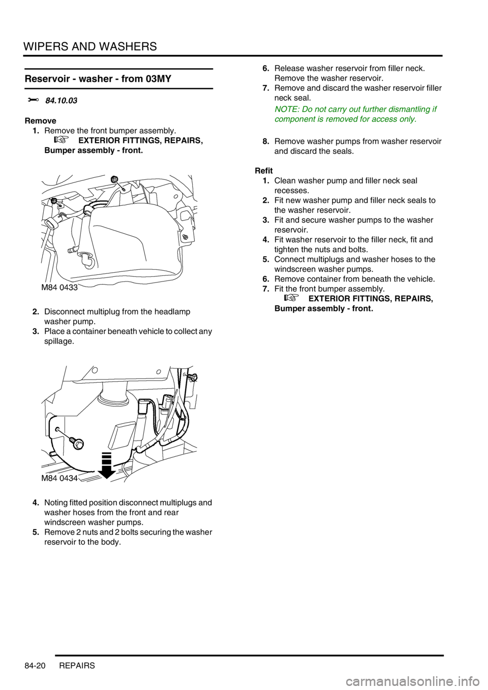
2.Disconnect multiplug from the headlamp
washer pump.
3.Place a container beneath vehicle to collect any
spillage.
4.Noting fitted position disconnect multiplugs and
washer hoses from the front and rear
windscreen washer pumps.
5.Remove 2 nuts and 2 bolts securing the washer
reservoir to the body.6.Release washer reservoir from filler neck.
Remove the washer reservoir.
7.Remove and discard the washer reservoir filler
neck seal.
NOTE: Do not carry out further dismantling if
component is removed for access only.
8.Remove washer pumps from washer reservoir
and discard the seals.
Refit
1.Clean washer pump and filler neck seal
recesses.
2.Fit new washer pump and filler neck seals to
the washer reservoir.
3.Fit and secure washer pumps to the washer
reservoir.
4.Fit washer reservoir to the filler neck, fit and
tighten the nuts and bolts.
5.Connect multiplugs and washer hoses to the
windscreen washer pumps.
6.Remove container from beneath the vehicle.
7.Fit the front bumper assembly.
+ EXTERIOR FITTINGS, REPAIRS,
Bumper assembly - front.
Page 1442 of 1672
WIPERS AND WASHERS
REPAIRS 84-21
Jet - washer - windscreen
$% 84.10.08
Remove
1.Carefully pull the elbow from the washer jet.
2.Place a protective covering around the washer
jet, then release and remove washer jet.
Refit
1.Fit washer jet to its location in the bonnet, and
remove the protective material.
2.Connect the washer tube, ensuring that it is
pushed fully onto the stub pipe.
Pump - washer - screen and headlamp
$% 84.10.21
The following procedure also covers removal of the
rear screen washer pump and the headlamp washer
pump.
Remove
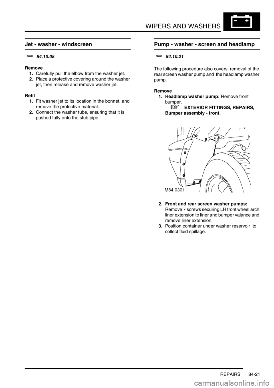
1. Headlamp washer pump: Remove front
bumper.
+ EXTERIOR FITTINGS, REPAIRS,
Bumper assembly - front.
2. Front and rear screen washer pumps:
Remove 7 screws securing LH front wheel arch
liner extension to liner and bumper valance and
remove liner extension.
3.Position container under washer reservoir to
collect fluid spillage.
Page 1443 of 1672
WIPERS AND WASHERS
84-22 REPAIRS
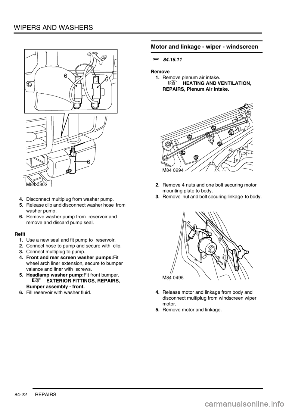
4.Disconnect multiplug from washer pump.
5.Release clip and disconnect washer hose from
washer pump.
6.Remove washer pump from reservoir and
remove and discard pump seal.
Refit
1.Use a new seal and fit pump to reservoir.
2.Connect hose to pump and secure with clip.
3.Connect multiplug to pump.
4. Front and rear screen washer pumps:Fit
wheel arch liner extension, secure to bumper
valance and liner with screws.
5. Headlamp washer pump:Fit front bumper.
+ EXTERIOR FITTINGS, REPAIRS,
Bumper assembly - front.
6.Fill reservoir with washer fluid.
Motor and linkage - wiper - windscreen
$% 84.15.11
Remove
1.Remove plenum air intake.
+ HEATING AND VENTILATION,
REPAIRS, Plenum Air Intake.
2.Remove 4 nuts and one bolt securing motor
mounting plate to body.
3.Remove nut and bolt securing linkage to body.
4.Release motor and linkage from body and
disconnect multiplug from windscreen wiper
motor.
5.Remove motor and linkage.