2002 LAND ROVER DISCOVERY alternator
[x] Cancel search: alternatorPage 1297 of 1672
PANEL REPAIRS
77-2-48 REPAIRS
Cross member outer rear panel (RH/LH
section)
In this procedure, the panel body side assembly and
the 'E' post assembly are replaced in conjunction
with either the RH or LH section of the cross member
outer rear panel.
Remove
1.Disconnect both battery leads, negative lead
first.
2.Disconnect leads/multiplug from alternator.
3.Remove 'E' post assembly.
+ PANEL REPAIRS, REPAIRS, 'E' post
assembly.
4.Remove rear folding step.
+ EXTERIOR FITTINGS, REPAIRS,
Rear folding step.
5. LH side: Remove exhaust tailpipe heatshield.
6.Remove relevant wiring.
Repair
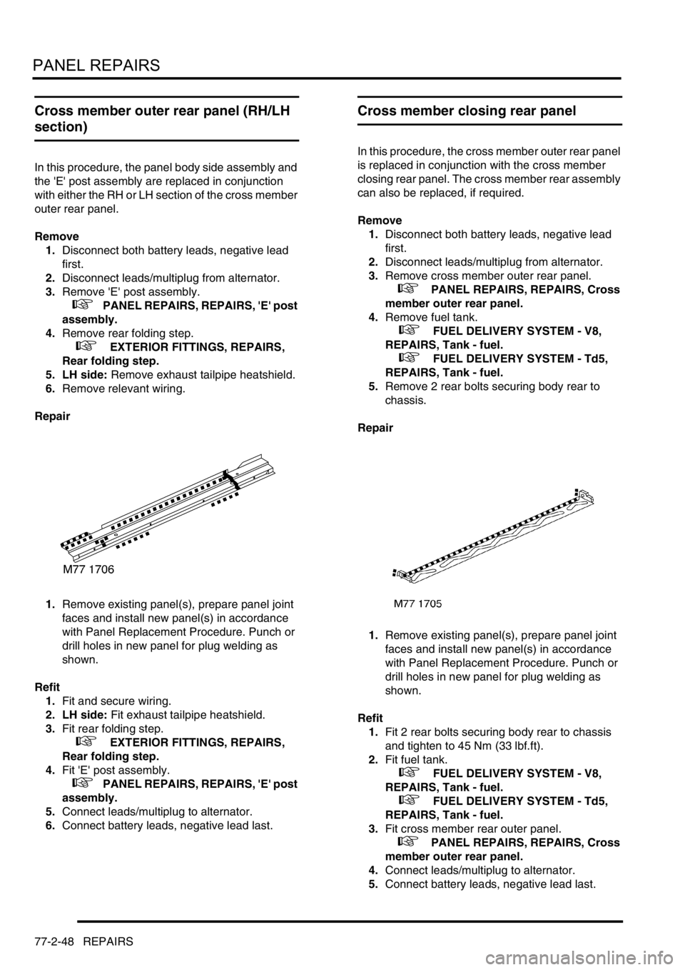
1.Remove existing panel(s), prepare panel joint
faces and install new panel(s) in accordance
with Panel Replacement Procedure. Punch or
drill holes in new panel for plug welding as
shown.
Refit
1.Fit and secure wiring.
2. LH side: Fit exhaust tailpipe heatshield.
3.Fit rear folding step.
+ EXTERIOR FITTINGS, REPAIRS,
Rear folding step.
4.Fit 'E' post assembly.
+ PANEL REPAIRS, REPAIRS, 'E' post
assembly.
5.Connect leads/multiplug to alternator.
6.Connect battery leads, negative lead last.
Cross member closing rear panel
In this procedure, the cross member outer rear panel
is replaced in conjunction with the cross member
closing rear panel. The cross member rear assembly
can also be replaced, if required.
Remove
1.Disconnect both battery leads, negative lead
first.
2.Disconnect leads/multiplug from alternator.
3.Remove cross member outer rear panel.
+ PANEL REPAIRS, REPAIRS, Cross
member outer rear panel.
4.Remove fuel tank.
+ FUEL DELIVERY SYSTEM - V8,
REPAIRS, Tank - fuel.
+ FUEL DELIVERY SYSTEM - Td5,
REPAIRS, Tank - fuel.
5.Remove 2 rear bolts securing body rear to
chassis.
Repair
1.Remove existing panel(s), prepare panel joint
faces and install new panel(s) in accordance
with Panel Replacement Procedure. Punch or
drill holes in new panel for plug welding as
shown.
Refit
1.Fit 2 rear bolts securing body rear to chassis
and tighten to 45 Nm (33 lbf.ft).
2.Fit fuel tank.
+ FUEL DELIVERY SYSTEM - V8,
REPAIRS, Tank - fuel.
+ FUEL DELIVERY SYSTEM - Td5,
REPAIRS, Tank - fuel.
3.Fit cross member rear outer panel.
+ PANEL REPAIRS, REPAIRS, Cross
member outer rear panel.
4.Connect leads/multiplug to alternator.
5.Connect battery leads, negative lead last.
Page 1298 of 1672
PANEL REPAIRS
REPAIRS 77-2-49
Cross member rear assembly
In this procedure, the cross member outer rear panel,
cross member closing rear panel, 'E' post assembly
and the panel body side assembly are replaced in
conjunction with the cross member rear assembly.
Remove
1.Disconnect both battery leads, negative lead
first.
2.Disconnect leads/multiplug from alternator.
3.Remove cross member closing rear panel.
+ PANEL REPAIRS, REPAIRS, Cross
member closing rear panel.
Repair
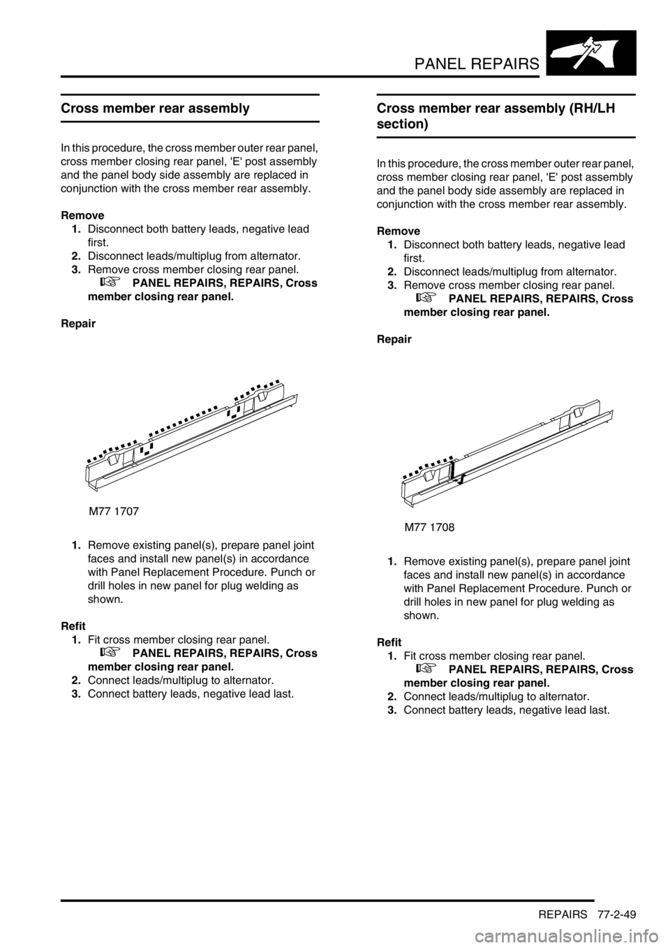
1.Remove existing panel(s), prepare panel joint
faces and install new panel(s) in accordance
with Panel Replacement Procedure. Punch or
drill holes in new panel for plug welding as
shown.
Refit
1.Fit cross member closing rear panel.
+ PANEL REPAIRS, REPAIRS, Cross
member closing rear panel.
2.Connect leads/multiplug to alternator.
3.Connect battery leads, negative lead last.
Cross member rear assembly (RH/LH
section)
In this procedure, the cross member outer rear panel,
cross member closing rear panel, 'E' post assembly
and the panel body side assembly are replaced in
conjunction with the cross member rear assembly.
Remove
1.Disconnect both battery leads, negative lead
first.
2.Disconnect leads/multiplug from alternator.
3.Remove cross member closing rear panel.
+ PANEL REPAIRS, REPAIRS, Cross
member closing rear panel.
Repair
1.Remove existing panel(s), prepare panel joint
faces and install new panel(s) in accordance
with Panel Replacement Procedure. Punch or
drill holes in new panel for plug welding as
shown.
Refit
1.Fit cross member closing rear panel.
+ PANEL REPAIRS, REPAIRS, Cross
member closing rear panel.
2.Connect leads/multiplug to alternator.
3.Connect battery leads, negative lead last.
Page 1299 of 1672
PANEL REPAIRS
77-2-50 REPAIRS
Rear floor complete assembly
Remove
1.Disconnect both battery leads, negative lead
first.
2.Disconnect leads/multiplug from alternator.
3.Remove loadspace carpet.
+ INTERIOR TRIM COMPONENTS,
REPAIRS, Carpet - loadspace.
4.Remove rear seats.
+ SEATS, REPAIRS, Seat - rear.
5.Remove rear carpet.
+ INTERIOR TRIM COMPONENTS,
REPAIRS, Carpet - rear.
6.Remove rear bumper assembly.
+ EXTERIOR FITTINGS, REPAIRS,
Bumper assembly - rear - up to 03MY.
7.Remove RH and LH mud flap and brackets.
8.Remove exhaust tail pipe heatshields.
9.Remove tread plates from rear door apertures.
10.Remove rear door aperture seal.
11.Remove tail door tread plate.
12.Remove loadspace carpet retainer.
13.Remove head lining rear trim finisher.
14.Remove tail door aperture seal.
15.Remove bolts securing body to chassis.
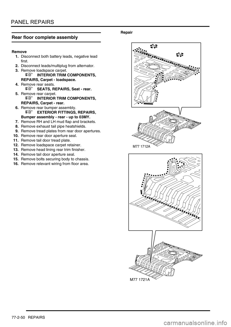
16.Remove relevant wiring from floor area.Repair
M77 1712A
M77 1721A
Page 1300 of 1672
PANEL REPAIRS
REPAIRS 77-2-51
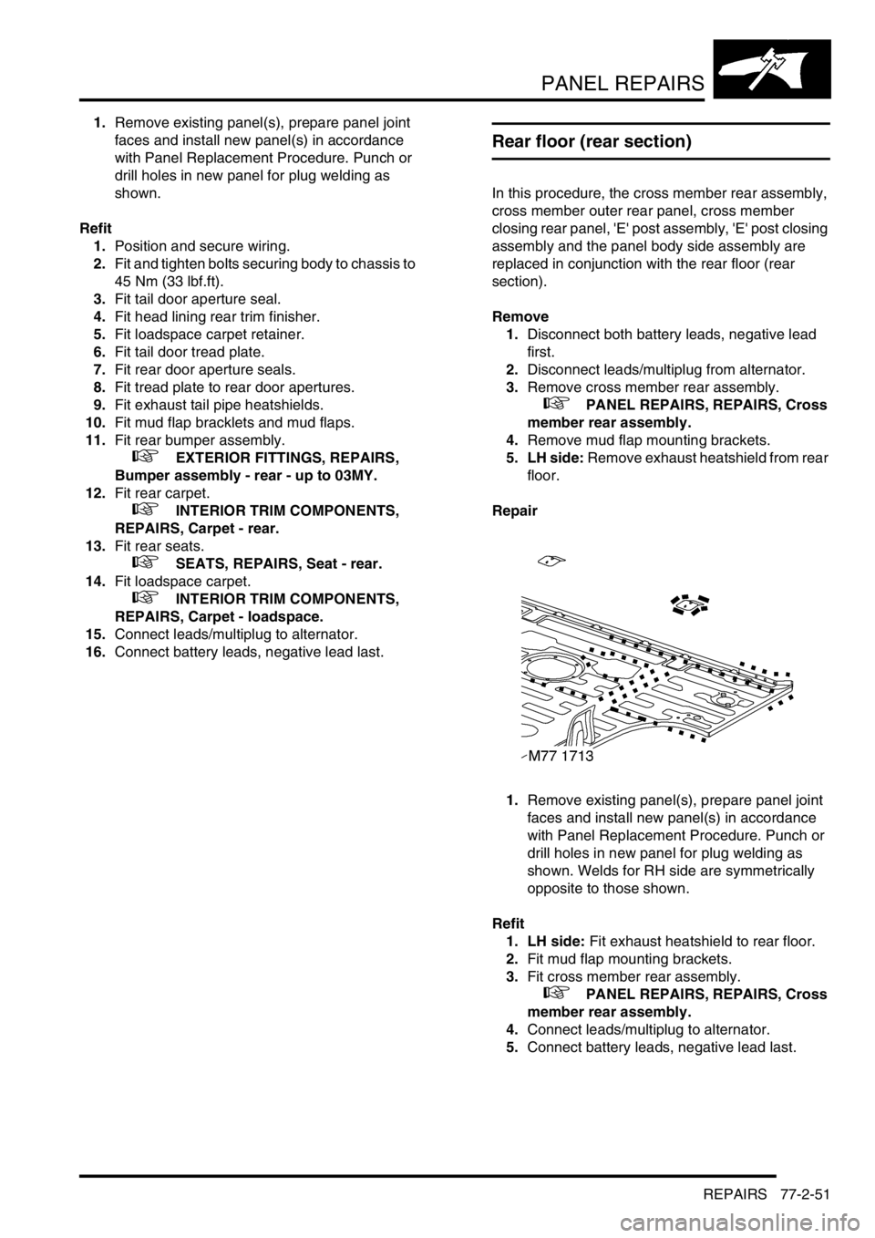
1.Remove existing panel(s), prepare panel joint
faces and install new panel(s) in accordance
with Panel Replacement Procedure. Punch or
drill holes in new panel for plug welding as
shown.
Refit
1.Position and secure wiring.
2.Fit and tighten bolts securing body to chassis to
45 Nm (33 lbf.ft).
3.Fit tail door aperture seal.
4.Fit head lining rear trim finisher.
5.Fit loadspace carpet retainer.
6.Fit tail door tread plate.
7.Fit rear door aperture seals.
8.Fit tread plate to rear door apertures.
9.Fit exhaust tail pipe heatshields.
10.Fit mud flap bracklets and mud flaps.
11.Fit rear bumper assembly.
+ EXTERIOR FITTINGS, REPAIRS,
Bumper assembly - rear - up to 03MY.
12.Fit rear carpet.
+ INTERIOR TRIM COMPONENTS,
REPAIRS, Carpet - rear.
13.Fit rear seats.
+ SEATS, REPAIRS, Seat - rear.
14.Fit loadspace carpet.
+ INTERIOR TRIM COMPONENTS,
REPAIRS, Carpet - loadspace.
15.Connect leads/multiplug to alternator.
16.Connect battery leads, negative lead last.
Rear floor (rear section)
In this procedure, the cross member rear assembly,
cross member outer rear panel, cross member
closing rear panel, 'E' post assembly, 'E' post closing
assembly and the panel body side assembly are
replaced in conjunction with the rear floor (rear
section).
Remove
1.Disconnect both battery leads, negative lead
first.
2.Disconnect leads/multiplug from alternator.
3.Remove cross member rear assembly.
+ PANEL REPAIRS, REPAIRS, Cross
member rear assembly.
4.Remove mud flap mounting brackets.
5. LH side: Remove exhaust heatshield from rear
floor.
Repair
1.Remove existing panel(s), prepare panel joint
faces and install new panel(s) in accordance
with Panel Replacement Procedure. Punch or
drill holes in new panel for plug welding as
shown. Welds for RH side are symmetrically
opposite to those shown.
Refit
1. LH side: Fit exhaust heatshield to rear floor.
2.Fit mud flap mounting brackets.
3.Fit cross member rear assembly.
+ PANEL REPAIRS, REPAIRS, Cross
member rear assembly.
4.Connect leads/multiplug to alternator.
5.Connect battery leads, negative lead last.
Page 1301 of 1672
PANEL REPAIRS
77-2-52 REPAIRS
Rear floor (RH/LH section)
In this procedure, the cross member rear assembly,
cross member outer rear panel (RH/LH section),
cross member closing rear panel, 'E' post assembly,
'E' post closing assembly and the panel body side
assembly are replaced in conjunction with the rear
floor (RH/LH section).
Remove
1.Disconnect both battery leads, negative lead
first.
2.Disconnect leads/multiplug from alternator.
3.Remove cross member rear assembly.
+ PANEL REPAIRS, REPAIRS, Cross
member rear assembly.
4.Remove mud flap mounting brackets.
5. LH side: Remove exhaust heatshield from rear
floor.
Repair
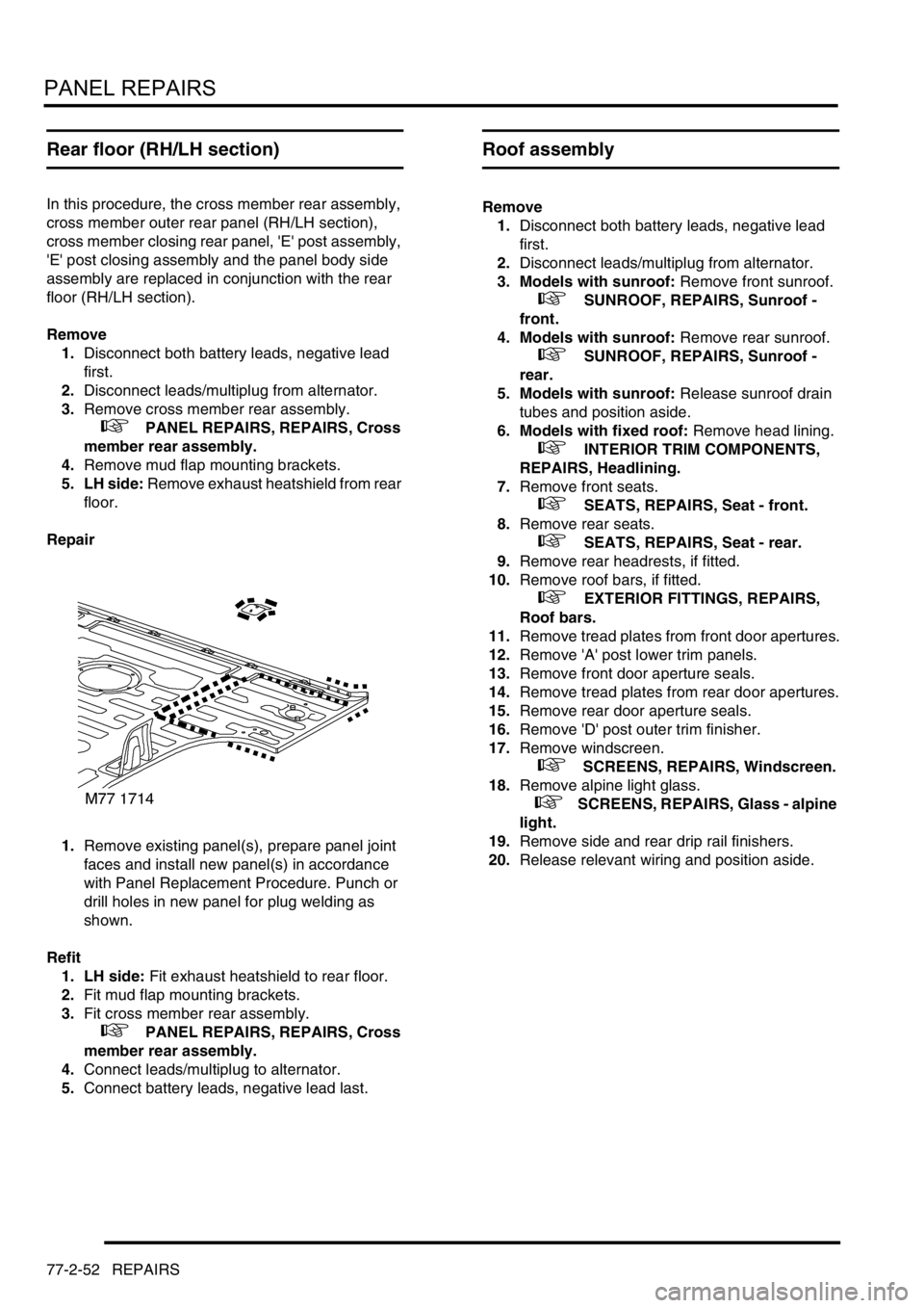
1.Remove existing panel(s), prepare panel joint
faces and install new panel(s) in accordance
with Panel Replacement Procedure. Punch or
drill holes in new panel for plug welding as
shown.
Refit
1. LH side: Fit exhaust heatshield to rear floor.
2.Fit mud flap mounting brackets.
3.Fit cross member rear assembly.
+ PANEL REPAIRS, REPAIRS, Cross
member rear assembly.
4.Connect leads/multiplug to alternator.
5.Connect battery leads, negative lead last.
Roof assembly
Remove
1.Disconnect both battery leads, negative lead
first.
2.Disconnect leads/multiplug from alternator.
3. Models with sunroof: Remove front sunroof.
+ SUNROOF, REPAIRS, Sunroof -
front.
4. Models with sunroof: Remove rear sunroof.
+ SUNROOF, REPAIRS, Sunroof -
rear.
5. Models with sunroof: Release sunroof drain
tubes and position aside.
6. Models with fixed roof: Remove head lining.
+ INTERIOR TRIM COMPONENTS,
REPAIRS, Headlining.
7.Remove front seats.
+ SEATS, REPAIRS, Seat - front.
8.Remove rear seats.
+ SEATS, REPAIRS, Seat - rear.
9.Remove rear headrests, if fitted.
10.Remove roof bars, if fitted.
+ EXTERIOR FITTINGS, REPAIRS,
Roof bars.
11.Remove tread plates from front door apertures.
12.Remove 'A' post lower trim panels.
13.Remove front door aperture seals.
14.Remove tread plates from rear door apertures.
15.Remove rear door aperture seals.
16.Remove 'D' post outer trim finisher.
17.Remove windscreen.
+ SCREENS, REPAIRS, Windscreen.
18.Remove alpine light glass.
+ SCREENS, REPAIRS, Glass - alpine
light.
19.Remove side and rear drip rail finishers.
20.Release relevant wiring and position aside.
Page 1302 of 1672
PANEL REPAIRS
REPAIRS 77-2-53
Repair
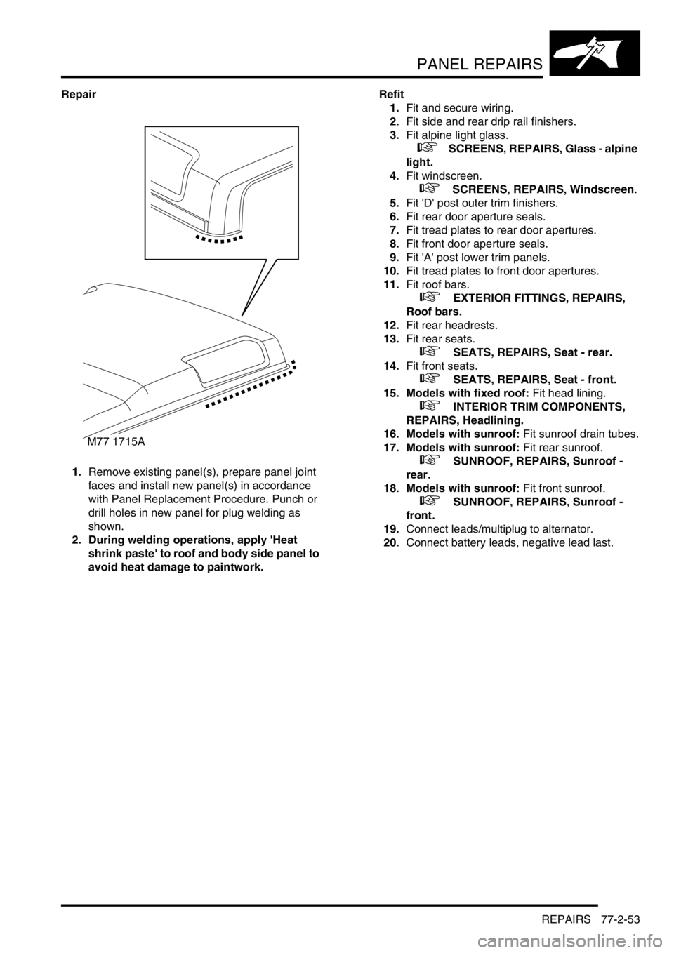
1.Remove existing panel(s), prepare panel joint
faces and install new panel(s) in accordance
with Panel Replacement Procedure. Punch or
drill holes in new panel for plug welding as
shown.
2. During welding operations, apply 'Heat
shrink paste' to roof and body side panel to
avoid heat damage to paintwork.Refit
1.Fit and secure wiring.
2.Fit side and rear drip rail finishers.
3.Fit alpine light glass.
+ SCREENS, REPAIRS, Glass - alpine
light.
4.Fit windscreen.
+ SCREENS, REPAIRS, Windscreen.
5.Fit 'D' post outer trim finishers.
6.Fit rear door aperture seals.
7.Fit tread plates to rear door apertures.
8.Fit front door aperture seals.
9.Fit 'A' post lower trim panels.
10.Fit tread plates to front door apertures.
11.Fit roof bars.
+ EXTERIOR FITTINGS, REPAIRS,
Roof bars.
12.Fit rear headrests.
13.Fit rear seats.
+ SEATS, REPAIRS, Seat - rear.
14.Fit front seats.
+ SEATS, REPAIRS, Seat - front.
15. Models with fixed roof: Fit head lining.
+ INTERIOR TRIM COMPONENTS,
REPAIRS, Headlining.
16. Models with sunroof: Fit sunroof drain tubes.
17. Models with sunroof: Fit rear sunroof.
+ SUNROOF, REPAIRS, Sunroof -
rear.
18. Models with sunroof: Fit front sunroof.
+ SUNROOF, REPAIRS, Sunroof -
front.
19.Connect leads/multiplug to alternator.
20.Connect battery leads, negative lead last.
M77 1715A
Page 1349 of 1672
HEATING AND VENTILATION
80-8DESCRIPTION AND OPERATION
Control panel
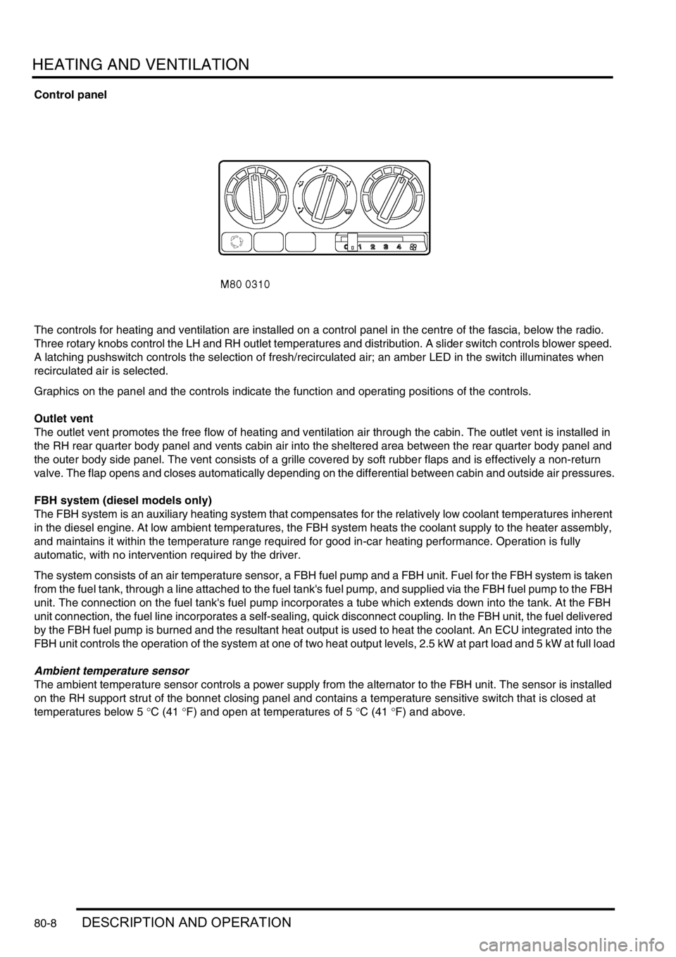
The controls for heating and ventilation are installed on a control panel in the centre of the fascia, below the radio.
Three rotary knobs control the LH and RH outlet temperatures and distribution. A slider switch controls blower speed.
A latching pushswitch controls the selection of fresh/recirculated air; an amber LED in the switch illuminates when
recirculated air is selected.
Graphics on the panel and the controls indicate the function and operating positions of the controls.
Outlet vent
The outlet vent promotes the free flow of heating and ventilation air through the cabin. The outlet vent is installed in
the RH rear quarter body panel and vents cabin air into the sheltered area between the rear quarter body panel and
the outer body side panel. The vent consists of a grille covered by soft rubber flaps and is effectively a non-return
valve. The flap opens and closes automatically depending on the differential between cabin and outside air pressures.
FBH system (diesel models only)
The FBH system is an auxiliary heating system that compensates for the relatively low coolant temperatures inherent
in the diesel engine. At low ambient temperatures, the FBH system heats the coolant supply to the heater assembly,
and maintains it within the temperature range required for good in-car heating performance. Operation is fully
automatic, with no intervention required by the driver.
The system consists of an air temperature sensor, a FBH fuel pump and a FBH unit. Fuel for the FBH system is taken
from the fuel tank, through a line attached to the fuel tank's fuel pump, and supplied via the FBH fuel pump to the FBH
unit. The connection on the fuel tank's fuel pump incorporates a tube which extends down into the tank. At the FBH
unit connection, the fuel line incorporates a self-sealing, quick disconnect coupling. In the FBH unit, the fuel delivered
by the FBH fuel pump is burned and the resultant heat output is used to heat the coolant. An ECU integrated into the
FBH unit controls the operation of the system at one of two heat output levels, 2.5 kW at part load and 5 kW at full load
Ambient temperature sensor
The ambient temperature sensor controls a power supply from the alternator to the FBH unit. The sensor is installed
on the RH support strut of the bonnet closing panel and contains a temperature sensitive switch that is closed at
temperatures below 5
°C (41 °F) and open at temperatures of 5 °C (41 °F) and above.
Page 1351 of 1672
HEATING AND VENTILATION
80-10DESCRIPTION AND OPERATION
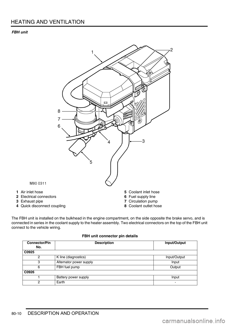
FBH unit
1Air inlet hose
2Electrical connectors
3Exhaust pipe
4Quick disconnect coupling5Coolant inlet hose
6Fuel supply line
7Circulation pump
8Coolant outlet hose
The FBH unit is installed on the bulkhead in the engine compartment, on the side opposite the brake servo, and is
connected in series in the coolant supply to the heater assembly. Two electrical connectors on the top of the FBH unit
connect to the vehicle wiring.
FBH unit connector pin details
Connector/Pin
No.Description Input/Output
C0925
2 K line (diagnostics) Input/Output
3 Alternator power supply Input
6 FBH fuel pump Output
C0926
1 Battery power supply Input
2Earth -