Page 1646 of 1672

INSTRUMENTS
DESCRIPTION AND OPERATION 88-19
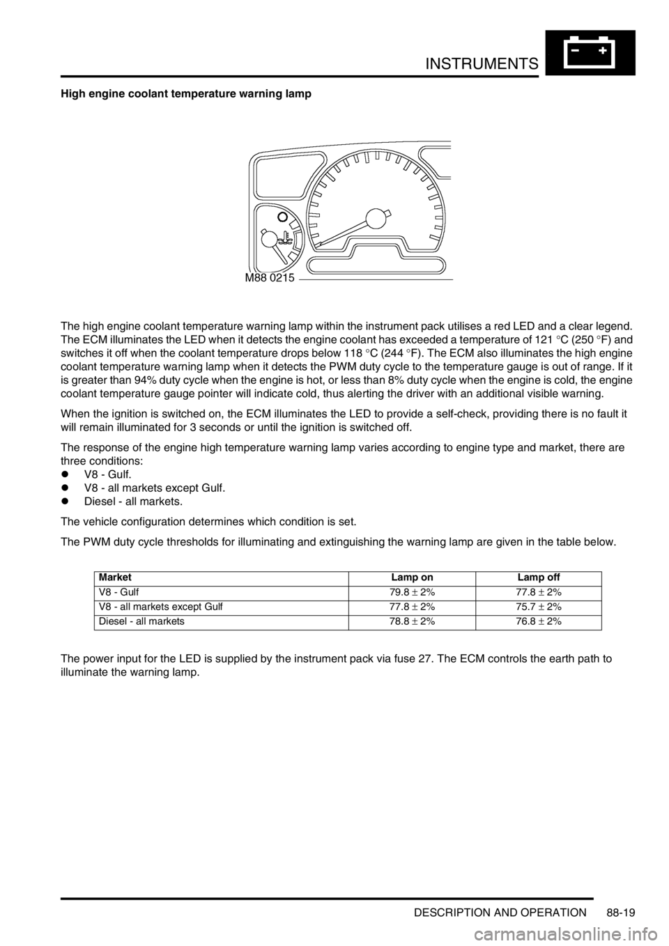
High engine coolant temperature warning lamp
The high engine coolant temperature warning lamp within the instrument pack utilises a red LED and a clear legend.
The ECM illuminates the LED when it detects the engine coolant has exceeded a temperature of 121
°C (250 °F) and
switches it off when the coolant temperature drops below 118
°C (244 °F). The ECM also illuminates the high engine
coolant temperature warning lamp when it detects the PWM duty cycle to the temperature gauge is out of range. If it
is greater than 94% duty cycle when the engine is hot, or less than 8% duty cycle when the engine is cold, the engine
coolant temperature gauge pointer will indicate cold, thus alerting the driver with an additional visible warning.
When the ignition is switched on, the ECM illuminates the LED to provide a self-check, providing there is no fault it
will remain illuminated for 3 seconds or until the ignition is switched off.
The response of the engine high temperature warning lamp varies according to engine type and market, there are
three conditions:
lV8 - Gulf.
lV8 - all markets except Gulf.
lDiesel - all markets.
The vehicle configuration determines which condition is set.
The PWM duty cycle thresholds for illuminating and extinguishing the warning lamp are given in the table below.
The power input for the LED is supplied by the instrument pack via fuse 27. The ECM controls the earth path to
illuminate the warning lamp.
Market Lamp on Lamp off
V8 - Gulf 79.8 ± 2% 77.8 ± 2%
V8 - all markets except Gulf 77.8 ± 2% 75.7 ± 2%
Diesel - all markets 78.8 ± 2% 76.8 ± 2%
Page 1650 of 1672

INSTRUMENTS
DESCRIPTION AND OPERATION 88-23
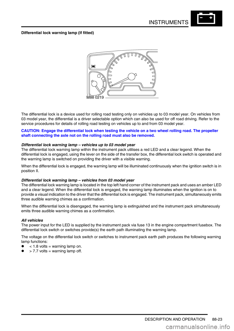
Differential lock warning lamp (If fitted)
The differential lock is a device used for rolling road testing only on vehicles up to 03 model year. On vehicles from
03 model year, the differential is a driver selectable option which can also be used for off road driving. Refer to the
service procedures for details of rolling road testing on vehicles up to and from 03 model year.
CAUTION: Engage the differential lock when testing the vehicle on a two wheel rolling road. The propeller
shaft connecting the axle not on the rolling road must also be removed.
Differential lock warning lamp – vehicles up to 03 model year
The differential lock warning lamp within the instrument pack utilises a red LED and a clear legend. When the
differential lock is engaged, using the lever on the side of the transfer box, the differential lock switch is operated and
the warning lamp is switched on providing the driver with a visible warning.
When the differential lock is engaged, the warning lamp will be illuminated continuously when the ignition switch is in
position II.
Differential lock warning lamp – vehicles from 03 model year
The differential lock warning lamp is located in the top left hand corner of the instrument pack and uses an amber LED
and a clear legend. When the differential lock is engaged, the warning lamp illuminates when the ignition is on to
provide a visual indication to the driver that the differential lock is engaged. The instrument pack, simultaneously emits
three audible warning chimes as a confirmation.
When the differential lock is disengaged, the warning lamp is extinguished and the instrument pack simultaneously
emits three audible warning chimes as a confirmation.
All vehicles
The power input for the LED is supplied by the instrument pack via fuse 13 in the engine compartment fusebox. The
differential lock switch or switches provide(s) the earth path illuminating the warning lamp.
The voltage on the differential lock switch or switches to instrument pack earth path produces the following warning
lamp functions:
l< 1.8 volts = warning lamp on.
l> 7.7 volts = warning lamp off.
Page 1655 of 1672
INSTRUMENTS
88-28 DESCRIPTION AND OPERATION
Glow plug warning lamp
The glow plug warning lamp within the instrument pack utilises an amber LED and a clear legend. On vehicles with
diesel engines the LED illuminates when the ECM operates the glow plugs. After a predetermined time calculated by
the ECM, dependent on engine temperature, the LED is switched off providing the driver with a visible warning that
the engine can be started.
The power input for the LED is supplied by the instrument pack via fuse 27. The ECM provides the earth path to
illuminate the warning lamp.
The voltage on the earth path from the ECM to the instrument pack is as follows:
l< 1.8 volts = warning lamp on.
l> 7.7 volts = warning lamp off.
Page 1656 of 1672
INSTRUMENTS
DESCRIPTION AND OPERATION 88-29
Water in fuel filter warning lamp
The water in fuel filter warning lamp within the instrument pack utilises an amber LED and a clear legend. On vehicles
with diesel engines the LED is illuminated when the water sensor detects water is present in the fuel filter, providing
the driver with a visible warning.
When the ignition is switched on, the instrument pack illuminates the LED to provide a self-check, providing there is
no water present in the fuel filter it will remain illuminated for 3 seconds or until the ignition is switched off.
The power input for the LED is supplied by the instrument pack via fuse 27. The water sensor provides the earth path
to illuminate the warning lamp. The voltage on the earth path from the sensor to the instrument pack is as follows:
l< 1.8 volts = warning lamp on.
l> 7.7 volts = warning lamp off.
Page 1657 of 1672
INSTRUMENTS
88-30 DESCRIPTION AND OPERATION
Water sensor
On vehicles with diesel engines a water sensor is located in the bottom of the fuel filter. The sensor utilises the
different resistance properties between water and diesel fuel to determines the presence of water in the fuel.
The sensor receives a battery voltage supply from the fuel pump relay. The sensor output is supplied to the instrument
pack. The water sensor provides the earth path to illuminate the warning lamp.
l< 1.8 volts = warning lamp on.
l> 7.7 volts = warning lamp off.
Page 1660 of 1672

INSTRUMENTS
DESCRIPTION AND OPERATION 88-33
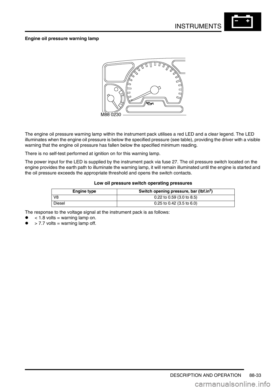
Engine oil pressure warning lamp
The engine oil pressure warning lamp within the instrument pack utilises a red LED and a clear legend. The LED
illuminates when the engine oil pressure is below the specified pressure (see table), providing the driver with a visible
warning that the engine oil pressure has fallen below the specified minimum reading.
There is no self-test performed at ignition on for this warning lamp.
The power input for the LED is supplied by the instrument pack via fuse 27. The oil pressure switch located on the
engine provides the earth path to illuminate the warning lamp, it will remain illuminated until the engine is started and
the oil pressure exceeds the appropriate threshold and opens the switch contacts.
Low oil pressure switch operating pressures
The response to the voltage signal at the instrument pack is as follows:
l< 1.8 volts = warning lamp on.
l> 7.7 volts = warning lamp off.
Engine type Switch opening pressure, bar (lbf.in2)
V8 0.22 to 0.59 (3.0 to 8.5)
Diesel 0.25 to 0.42 (3.5 to 6.0)
Page 1661 of 1672
INSTRUMENTS
88-34 DESCRIPTION AND OPERATION
Alternator charge warning lamp
The alternator charge warning lamp within the instrument pack utilises a red LED and a clear legend. The LED
illuminates when the alternator output voltage is less than 2 volts. When the alternator output is greater than 7.6 volts
the LED is extinguished, providing the driver with a visible warning that the alternator is charging.
When the ignition is switched on, and the LED illuminates, it will remain illuminated until the engine is started and
voltage is above the predetermined parameter, or the ignition is switched off providing there is no fault.
The power input for the LED is supplied by the instrument pack via fuse 27. The alternator provides a signal to
illuminate the warning lamp by means of a hard wired connection to the instrument pack.
The response to the voltage signal at the instrument pack is as follows:
l< 2.0 volts = warning lamp on.
l> 7.6 volts = warning lamp off.
Page 1663 of 1672

INSTRUMENTS
88-36 DESCRIPTION AND OPERATION
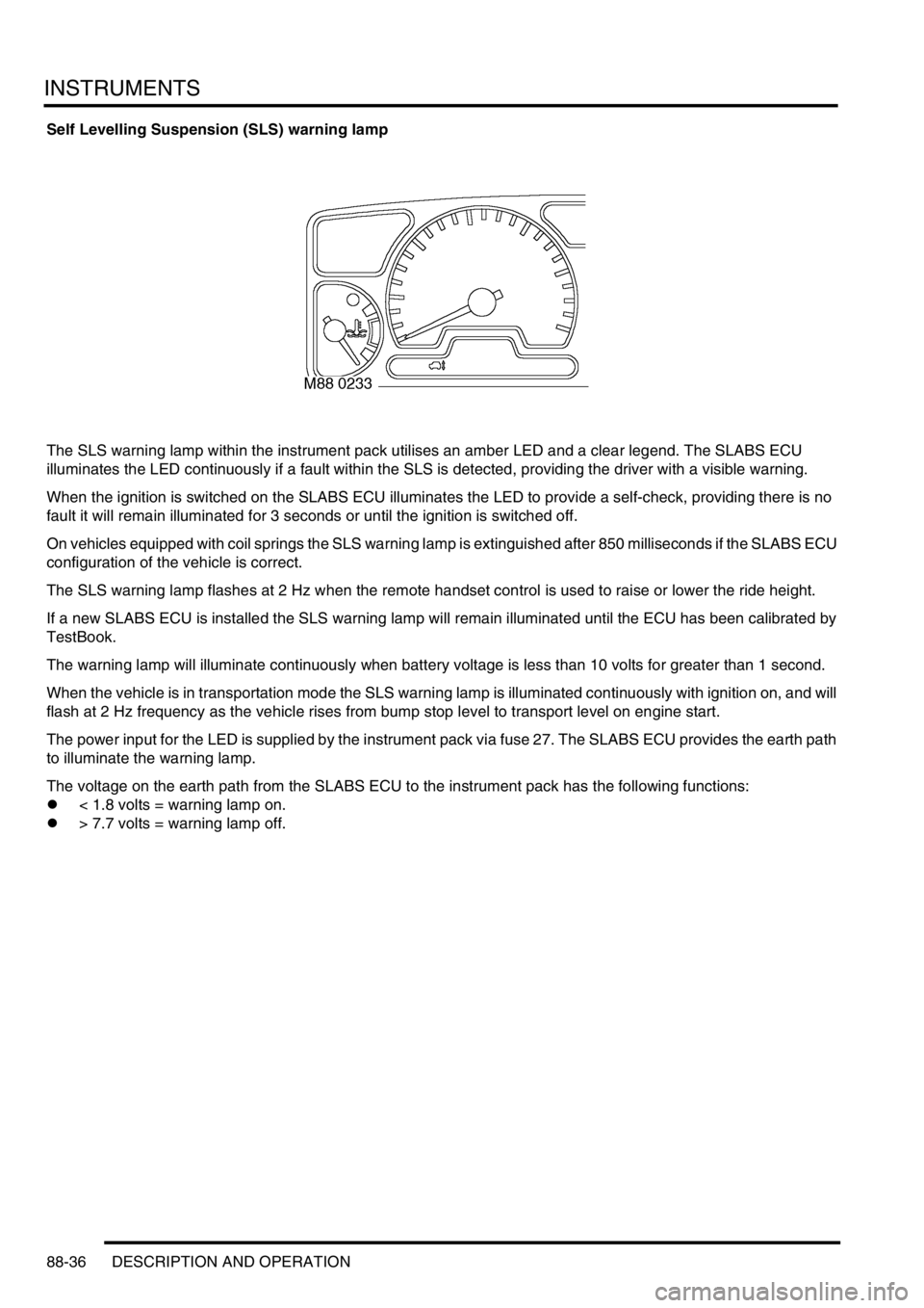
Self Levelling Suspension (SLS) warning lamp
The SLS warning lamp within the instrument pack utilises an amber LED and a clear legend. The SLABS ECU
illuminates the LED continuously if a fault within the SLS is detected, providing the driver with a visible warning.
When the ignition is switched on the SLABS ECU illuminates the LED to provide a self-check, providing there is no
fault it will remain illuminated for 3 seconds or until the ignition is switched off.
On vehicles equipped with coil springs the SLS warning lamp is extinguished after 850 milliseconds if the SLABS ECU
configuration of the vehicle is correct.
The SLS warning lamp flashes at 2 Hz when the remote handset control is used to raise or lower the ride height.
If a new SLABS ECU is installed the SLS warning lamp will remain illuminated until the ECU has been calibrated by
TestBook.
The warning lamp will illuminate continuously when battery voltage is less than 10 volts for greater than 1 second.
When the vehicle is in transportation mode the SLS warning lamp is illuminated continuously with ignition on, and will
flash at 2 Hz frequency as the vehicle rises from bump stop level to transport level on engine start.
The power input for the LED is supplied by the instrument pack via fuse 27. The SLABS ECU provides the earth path
to illuminate the warning lamp.
The voltage on the earth path from the SLABS ECU to the instrument pack has the following functions:
l< 1.8 volts = warning lamp on.
l> 7.7 volts = warning lamp off.