Page 1516 of 1672
ALARM SYSTEM AND HORN
DESCRIPTION AND OPERATION 86-4-7
Driver's door key lock/unlock switches
The BCU uses the driver's door key lock/unlock switches to activate and deactivate the alarm system. Two separate
switches are incorporated into the key lock of the driver's door.
Input/Output
The input from the driver's door key lock/unlock switches to the BCU is either zero volts or an open circuit. Zero volts
indicates the key lock is in the lock or unlock position. An open circuit indicates the key lock is in the centre position.
When the BCU senses an open circuit, it pulls the input high internally.
The driver's door key lock /unlock switches have a dedicated signal input to the BCU. This allows the BCU to identify
the lock/unlock position.
TestBook provides the ability to monitor the real time state of the driver's door key lock/unlock switches.
Page 1517 of 1672
ALARM SYSTEM AND HORN
86-4-8 DESCRIPTION AND OPERATION
Door lock actuators
The door lock actuators are D type latches. The door locks allow the vehicle to be locked/unlocked and super locked
to prevent access to the vehicle via the interior door handles.
Input/Output
The driver's door lock actuator has a dedicated 12 volts power supply from the passenger compartment fuse box to
energise the locking action of the door lock actuator. The passenger and rear door lock actuators share a 12 volts
power supply from the passenger compartment fuse box to energise the locking action of the door lock actuator.
To perform the super locking action all the door lock actuators receive a 12 volts power supply from the passenger
compartment fuse box.
To perform the unlocking action for all the doors, a 12 volts power supply from the passenger compartment fuse box
is supplied to the door lock actuators.
Page 1518 of 1672
ALARM SYSTEM AND HORN
DESCRIPTION AND OPERATION 86-4-9
Bonnet switch
The BCU uses a plunger type switch to determine if the bonnet has been forcibly opened when the alarm has been
set. The switch is located under the bonnet on the left hand side of the vehicle when viewed from the rear.
Input/Output
When the bonnet is closed the bonnet activated alarm switch is in an open condition and the input to the BCU is more
than 6 volts, in which case the BCU pulls the input high internally. When the bonnet is open the bonnet activated alarm
switch is closed and the input to the BCU is less than 2 volts.
The bonnet activated alarm switch has a dedicated signal input to the BCU. This allows the BCU to identify the
position of the bonnet.
TestBook provides the ability to monitor the real time state of the switch.
Page 1519 of 1672
ALARM SYSTEM AND HORN
86-4-10 DESCRIPTION AND OPERATION
Volumetric sensors
The BCU uses volumetric sensors to detect any change in air movement within the vehicle. There are two sensors
located in the headlining of the vehicle.
Input/Output
The sensors require a regulated power supply of 12 volts, via the BCU. When a change in air movement is detected
the sensors generate a 5 Hz pulse train to the BCU.
Each of the sensors have a dedicated signal input to the BCU. Power to the sensors is supplied by the BCU.
TestBook provides the ability to monitor the real time state of the sensors.
Page 1520 of 1672

ALARM SYSTEM AND HORN
DESCRIPTION AND OPERATION 86-4-11
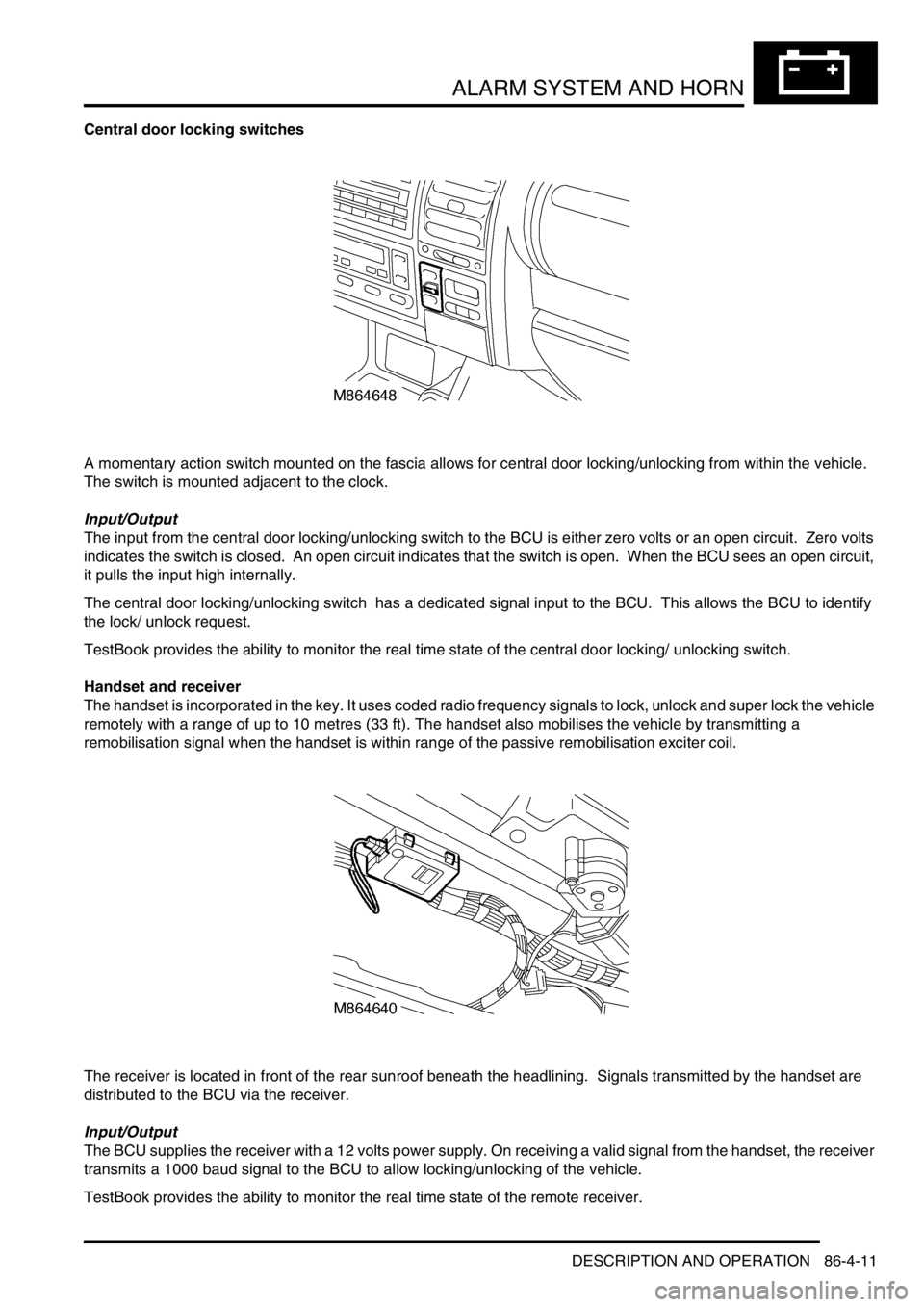
Central door locking switches
A momentary action switch mounted on the fascia allows for central door locking/unlocking from within the vehicle.
The switch is mounted adjacent to the clock.
Input/Output
The input from the central door locking/unlocking switch to the BCU is either zero volts or an open circuit. Zero volts
indicates the switch is closed. An open circuit indicates that the switch is open. When the BCU sees an open circuit,
it pulls the input high internally.
The central door locking/unlocking switch has a dedicated signal input to the BCU. This allows the BCU to identify
the lock/ unlock request.
TestBook provides the ability to monitor the real time state of the central door locking/ unlocking switch.
Handset and receiver
The handset is incorporated in the key. It uses coded radio frequency signals to lock, unlock and super lock the vehicle
remotely with a range of up to 10 metres (33 ft). The handset also mobilises the vehicle by transmitting a
remobilisation signal when the handset is within range of the passive remobilisation exciter coil.
The receiver is located in front of the rear sunroof beneath the headlining. Signals transmitted by the handset are
distributed to the BCU via the receiver.
Input/Output
The BCU supplies the receiver with a 12 volts power supply. On receiving a valid signal from the handset, the receiver
transmits a 1000 baud signal to the BCU to allow locking/unlocking of the vehicle.
TestBook provides the ability to monitor the real time state of the remote receiver.
Page 1521 of 1672
ALARM SYSTEM AND HORN
86-4-12 DESCRIPTION AND OPERATION
Passive remobilisation exciter coil
The passive remobilisation exciter coil consists of a coil around the steering column lock. The coil energises to create
a magnetic field when the ignition is switched to position II.
This coil activates the handset initiating the mobilisation of the vehicle.
Input/Output
The input to the passive remobilisation exciter coil from the BCU is a 12 volts 125 kHz sinewave. The passive
remobilisation exciter coil also receives an ignition controlled power supply via fuse 20 (15 amperes) located in the
engine compartment fuse box. On receiving these signals, a magnetic field is generated which activates the handset
to produce a remobilisation signal. This remobilisation signal is transmitted to the remote receiver and onto the BCU
to allow the engine to start.
Page 1522 of 1672

ALARM SYSTEM AND HORN
DESCRIPTION AND OPERATION 86-4-13
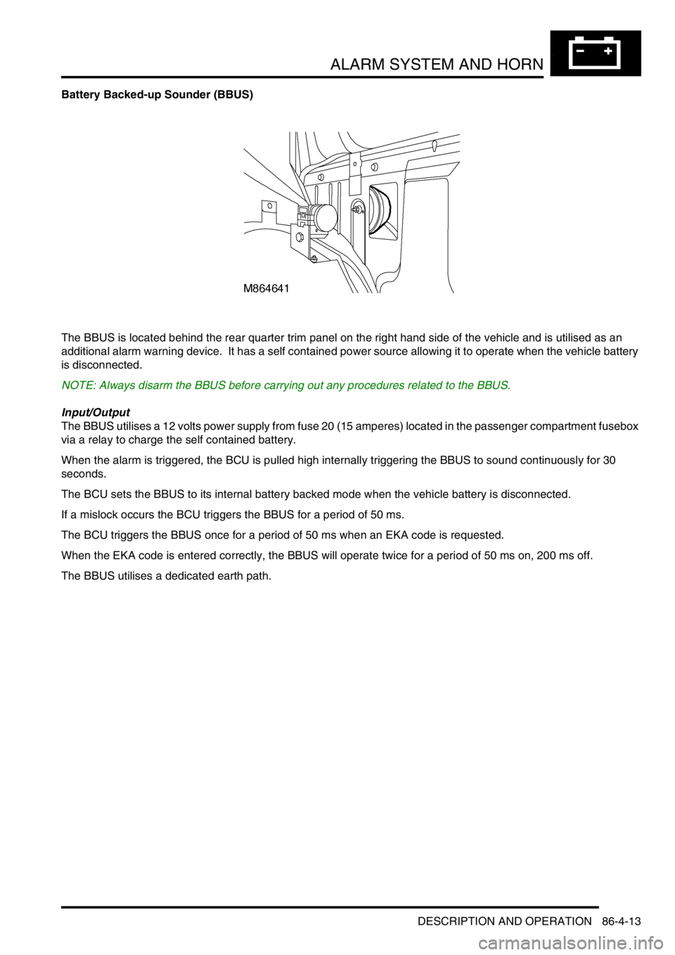
Battery Backed-up Sounder (BBUS)
The BBUS is located behind the rear quarter trim panel on the right hand side of the vehicle and is utilised as an
additional alarm warning device. It has a self contained power source allowing it to operate when the vehicle battery
is disconnected.
NOTE: Always disarm the BBUS before carrying out any procedures related to the BBUS.
Input/Output
The BBUS utilises a 12 volts power supply from fuse 20 (15 amperes) located in the passenger compartment fusebox
via a relay to charge the self contained battery.
When the alarm is triggered, the BCU is pulled high internally triggering the BBUS to sound continuously for 30
seconds.
The BCU sets the BBUS to its internal battery backed mode when the vehicle battery is disconnected.
If a mislock occurs the BCU triggers the BBUS for a period of 50 ms.
The BCU triggers the BBUS once for a period of 50 ms when an EKA code is requested.
When the EKA code is entered correctly, the BBUS will operate twice for a period of 50 ms on, 200 ms off.
The BBUS utilises a dedicated earth path.
Page 1523 of 1672

ALARM SYSTEM AND HORN
86-4-14 DESCRIPTION AND OPERATION
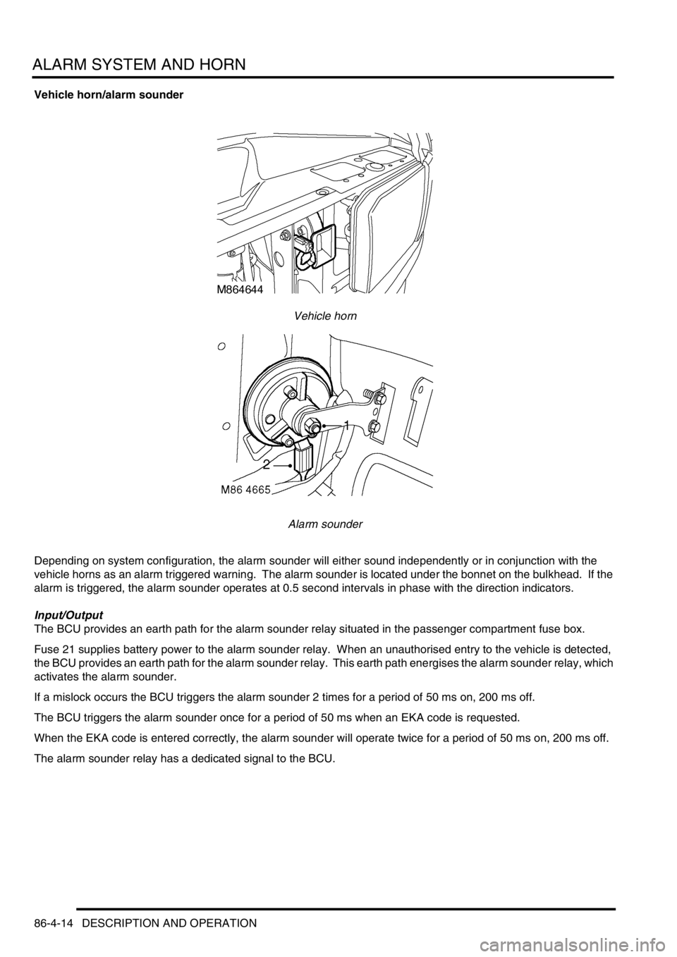
Vehicle horn/alarm sounder
Vehicle horn
Alarm sounder
Depending on system configuration, the alarm sounder will either sound independently or in conjunction with the
vehicle horns as an alarm triggered warning. The alarm sounder is located under the bonnet on the bulkhead. If the
alarm is triggered, the alarm sounder operates at 0.5 second intervals in phase with the direction indicators.
Input/Output
The BCU provides an earth path for the alarm sounder relay situated in the passenger compartment fuse box.
Fuse 21 supplies battery power to the alarm sounder relay. When an unauthorised entry to the vehicle is detected,
the BCU provides an earth path for the alarm sounder relay. This earth path energises the alarm sounder relay, which
activates the alarm sounder.
If a mislock occurs the BCU triggers the alarm sounder 2 times for a period of 50 ms on, 200 ms off.
The BCU triggers the alarm sounder once for a period of 50 ms when an EKA code is requested.
When the EKA code is entered correctly, the alarm sounder will operate twice for a period of 50 ms on, 200 ms off.
The alarm sounder relay has a dedicated signal to the BCU.