2002 LAND ROVER DISCOVERY oil temperature
[x] Cancel search: oil temperaturePage 612 of 1672

COOLING SYSTEM - V8
DESCRIPTION AND OPERATION 26-2-11
Viscous fan operation
A = Cold, B = Hot
1Drive plate
2Fan body
3Clearance
4Valve plate
5Valve
6Bi-metallic coil7Fluid seals
8Ball race
9Fluid chamber
10Reservoir
11Return port
When the engine is off and the fan is not rotating, the silicone fluid stabilises within the fluid chamber and the reservoir.
The fluid levels equalise due to the return port in the valve plate being open between the fluid chamber and the
reservoir. In this condition, when the engine is started, silicone fluid is present in the fluid chamber and causes drag
to occur between the drive plate and the body. This causes the fan to operate initially when the engine is started.
As the fan speed increases, centrifugal force and a scoop formed on the fluid chamber side of the valve plate, pushes
the silicone fluid through the return port in the valve plate into the reservoir. As the fluid chamber empties, the drag
between the drive plate and body is reduced, causing the drive plate to slip. This reduces the rotational speed of the
fan and allows it to 'freewheel'.
When the coolant temperature is low, the heat emitted from the radiator does not affect the bi-metallic coil. The valve
remains closed, preventing fluid escaping from the reservoir into the fluid chamber. In this condition the fan will
'freewheel' at a slow speed.
Page 613 of 1672

COOLING SYSTEM - V8
26-2-12 DESCRIPTION AND OPERATION
As the coolant temperature increases, the heat emitted from the radiator causes the bi-metallic coil to tighten. This
movement of the coil moves the valve to which it is attached. The rotation of the valve exposes ports in the valve plate
which allow silicone fluid to spill into the fluid chamber. As the fluid flows into the clearance between the annular
grooves in the drive plate and body, drag is created between the two components. The drag is due to the viscosity
and shear qualities of the silicone fluid and cause the drive plate to rotate the body and fan blades.
As the coolant temperature decreases, the bi-metallic coil expands, rotating the valve and closing off the ports in the
valve plate. When the valve is closed, centrifugal force pushes silicone fluid through the return port, emptying the fluid
chamber. As the fluid chamber empties, the drag between the drive plate and the body is reduced and the body slips
on the drive plate, slowing the rotational speed of the fan.
Page 617 of 1672

COOLING SYSTEM - V8
26-2-16 REPAIRS
8.Remove 6 scrivets and remove LH and RH air
deflectors from front panel. Disconnect
multiplug of gearbox oil temperature sensor
(arrowed).
9.Remove nut and move horn aside. 10.Remove 2 bolts securing radiator LH and RH
upper mounting brackets to body panel and
remove brackets.
11.Remove 4 screws securing air conditioning
condenser LH and RH upper mounting
brackets to condenser.
12.Remove brackets with rubber mounts from
radiator extension brackets.
13.Position absorbent cloth under each cooler
hose to collect oil spillage.
14.Push against coupling release rings and
disconnect hoses from gearbox oil cooler.
CAUTION: Always fit plugs to open
connections to prevent contamination.
15. If fitted: Push against coupling release rings
and disconnect hoses from engine oil cooler.
Page 618 of 1672

COOLING SYSTEM - V8
REPAIRS 26-2-17
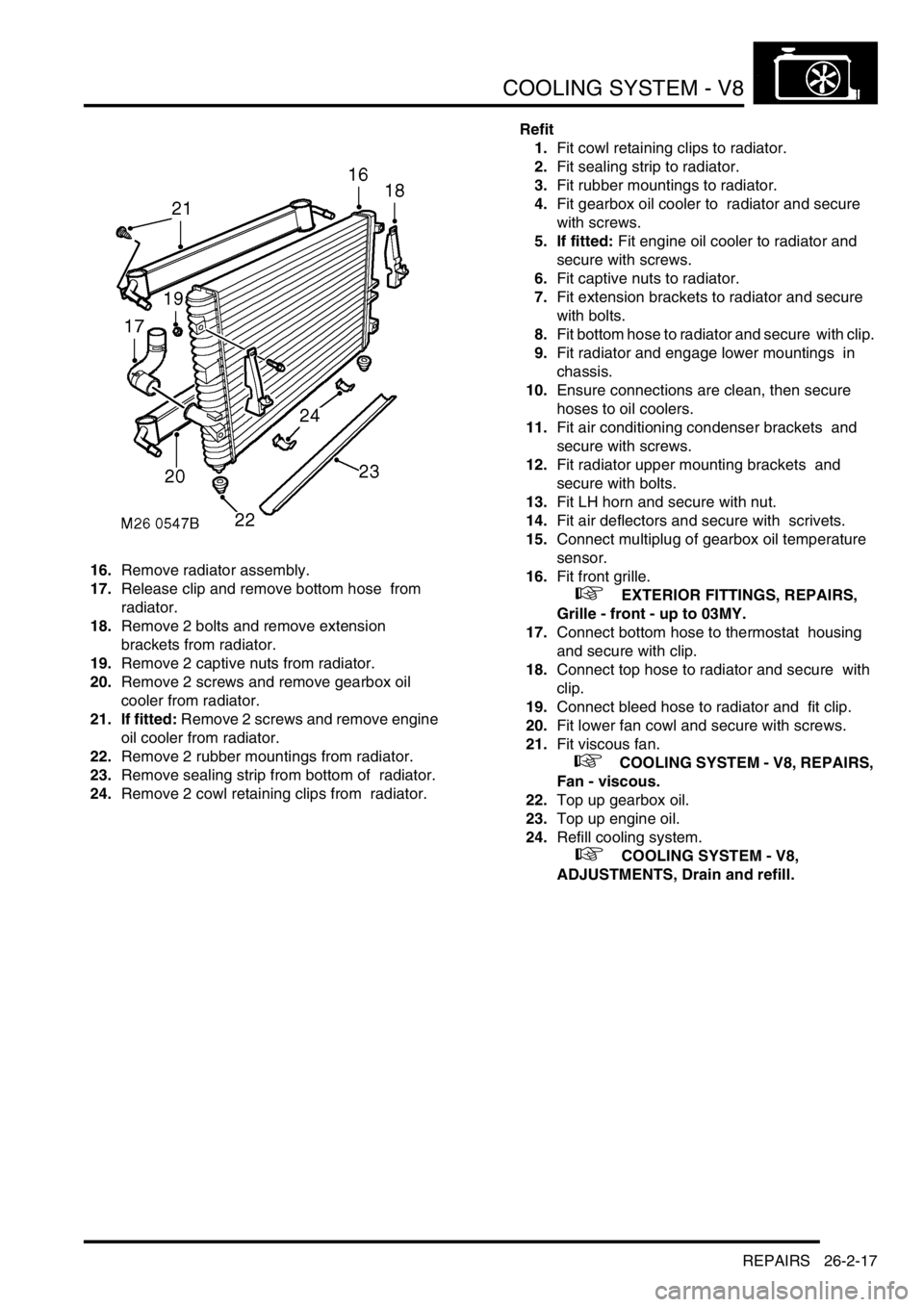
16.Remove radiator assembly.
17.Release clip and remove bottom hose from
radiator.
18.Remove 2 bolts and remove extension
brackets from radiator.
19.Remove 2 captive nuts from radiator.
20.Remove 2 screws and remove gearbox oil
cooler from radiator.
21. If fitted: Remove 2 screws and remove engine
oil cooler from radiator.
22.Remove 2 rubber mountings from radiator.
23.Remove sealing strip from bottom of radiator.
24.Remove 2 cowl retaining clips from radiator. Refit
1.Fit cowl retaining clips to radiator.
2.Fit sealing strip to radiator.
3.Fit rubber mountings to radiator.
4.Fit gearbox oil cooler to radiator and secure
with screws.
5. If fitted: Fit engine oil cooler to radiator and
secure with screws.
6.Fit captive nuts to radiator.
7.Fit extension brackets to radiator and secure
with bolts.
8.Fit bottom hose to radiator and secure with clip.
9.Fit radiator and engage lower mountings in
chassis.
10.Ensure connections are clean, then secure
hoses to oil coolers.
11.Fit air conditioning condenser brackets and
secure with screws.
12.Fit radiator upper mounting brackets and
secure with bolts.
13.Fit LH horn and secure with nut.
14.Fit air deflectors and secure with scrivets.
15.Connect multiplug of gearbox oil temperature
sensor.
16.Fit front grille.
+ EXTERIOR FITTINGS, REPAIRS,
Grille - front - up to 03MY.
17.Connect bottom hose to thermostat housing
and secure with clip.
18.Connect top hose to radiator and secure with
clip.
19.Connect bleed hose to radiator and fit clip.
20.Fit lower fan cowl and secure with screws.
21.Fit viscous fan.
+ COOLING SYSTEM - V8, REPAIRS,
Fan - viscous.
22.Top up gearbox oil.
23.Top up engine oil.
24.Refill cooling system.
+ COOLING SYSTEM - V8,
ADJUSTMENTS, Drain and refill.
Page 697 of 1672

MANUAL GEARBOX - R380
37-14 REPAIRS
24.Remove clevis pin and 'C' washer securing low
ratio selector cable to lever and release cable
from lever housing.
25.Remove 2 cable ties securing cable to fuel
pipes.
26.Disconnect 2 Lucars from oil temperature
sensor and disconnect reverse lamp switch
multiplug.
27.Remove banjo bolts securing breather pipes
and discard sealing washers. 28.Remove bolt securing breather pipe 'P' clip and
release breather pipes.
29. If fitted: Disconnect 2 Lucars from differential
lock switch, release and disconnect transfer
box neutral sensor multiplug.
30. If fitted: Release harness from 2 retaining
clips.
31.Position container to catch oil spillage
32.Remove 3 bolts securing oil cooling pipe
housing to gearbox, release housing and
discard 'O' rings.
33.Using a second jack support the weight of the
engine.
Page 698 of 1672

MANUAL GEARBOX - R380
REPAIRS 37-15
34.Remove 14 bolts securing gearbox to engine.
35.With assistance, remove gearbox from engine.
Refit
1.Clean gearbox to engine mating faces, dowels
and dowel holes.
2.Raise gear gearbox on jack and align to clutch
and engine.
3.Fit bolts securing gearbox to engine and
tighten to 45 Nm (33 lbf.ft).
4.Lubricate and fit new 'O' rings to oil cooling
pipe housing.
5.Position coolant pipe housing, fit bolts and
tighten to 25 Nm (18 lbf.ft).
6. If fitted: Secure harness in retaining clips,
connect Lucars to differential lock warning
switch and multiplug to neutral sensor.
7.Position breather pipes and secure 'P' clip with
bolt.
8.Using new sealing washers fit breather pipe
banjo bolts and tighten to 15 Nm (11 lbf.ft).
9.Connect oil temperature sensor Lucars and
reverse lamp switch multiplug.
10.Position low ratio selector cable to housing and
secure with 'C' washer and clevis pin.
11.Secure cable to fuel pipes with new cable ties.
12.Raise gearbox, ensuring gear change lever is
located in grommet.
13.Fit gearbox mountings and tighten bolts to 85
Nm (63 lbf.ft). 14.Fit nuts to mountings and tighten to 48 Nm (37
lbf.ft).
15.Remove 3 bolts securing support plate to
gearbox.
16.Position clutch slave cylinder and heat shield,
fit bolts and tighten to 25 Nm (18 lbf.ft).
17.Clean handbrake back plate and mating face.
18.Position handbrake back plate, fit bolts and
tighten to 75 Nm (46 lbf.ft).
19.Clean handbrake drum.
20.Fit handbrake drum and tighten retaining
screw.
21.Clean propeller shafts and mating faces.
22.Position propeller shafts, align to marks and
tighten bolts to 47 Nm (35 lbf.ft).
23.Clean exhaust silencer and tail pipe mating
faces.
24.Position silencer and secure on mountings,
using a new gasket align to tail pipe, fit nuts
and tighten to 25 Nm (18 lbf.ft).
25.Position rear cross member, fit bolts and
tighten to 25 Nm (18 lbf.ft).
26.Refill gearbox with oil.
+ MAINTENANCE, PROCEDURES,
Manual gearbox.
27.Refill transfer gearbox oil.
+ MAINTENANCE, PROCEDURES,
Transfer box.
28.Fit front exhaust pipe.
+ MANIFOLDS AND EXHAUST
SYSTEMS - V8, REPAIRS, Front pipe.
29.Fit gear lever extension, fit clamp bolt and
tighten to 25 Nm (18 lbf.ft).
30.Fit gear lever trim and gear change knob.
31.Connect battery earth lead.
32. Fit battery cover and cooling fan cover and
secure fixings.
Page 701 of 1672

MANUAL GEARBOX - R380
37-18 REPAIRS
23.Remove clevis pin and 'C' washer securing low
ratio selector cable to lever and release cable
from lever housing.
24.Remove 2 cable ties securing cable to fuel
pipes.
25.Disconnect 2 Lucars from oil temperature
sensor and disconnect reverse lamp switch
multiplug.
26.Remove banjo bolts securing breather pipes
and discard sealing washers.
27.Remove bolt securing breather pipe 'P' clip and
release breather pipes. 28. If fitted: Disconnect 2 Lucars from differential
lock switch, release and disconnect transfer
box neutral sensor multiplug. Release harness
from 2 retaining clips.
29.Position container to catch oil spillage
30.Remove 2 bolts securing oil cooling pipe
housing to gearbox, release housing and
discard 'O' rings.
CAUTION: Always fit plugs to open
connections to prevent contamination.
31.Using a second jack support the weight of the
engine.
Page 702 of 1672

MANUAL GEARBOX - R380
REPAIRS 37-19
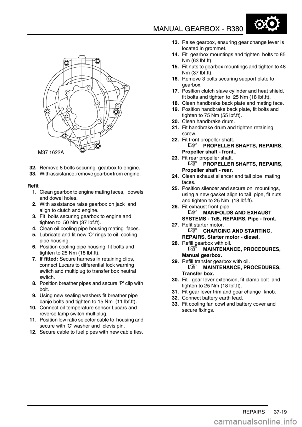
32.Remove 8 bolts securing gearbox to engine.
33.With assistance, remove gearbox from engine.
Refit
1.Clean gearbox to engine mating faces, dowels
and dowel holes.
2.With assistance raise gearbox on jack and
align to clutch and engine.
3.Fit bolts securing gearbox to engine and
tighten to 50 Nm (37 lbf.ft).
4.Clean oil cooling pipe housing mating faces.
5.Lubricate and fit new 'O' rings to oil cooling
pipe housing.
6.Position cooling pipe housing, fit bolts and
tighten to 25 Nm (18 lbf.ft).
7. If fitted: Secure harness in retaining clips,
connect Lucars to differential lock warning
switch and multiplug to transfer box neutral
switch.
8.Position breather pipes and secure 'P' clip with
bolt.
9.Using new sealing washers fit breather pipe
banjo bolts and tighten to 15 Nm (11 lbf.ft).
10.Connect oil temperature sensor Lucars and
reverse lamp switch multiplug.
11.Position low ratio selector cable to housing and
secure with 'C' washer and clevis pin.
12.Secure cable to fuel pipes with new cable ties. 13.Raise gearbox, ensuring gear change lever is
located in grommet.
14.Fit gearbox mountings and tighten bolts to 85
Nm (63 lbf.ft).
15.Fit nuts to gearbox mountings and tighten to 48
Nm (37 lbf.ft).
16.Remove 3 bolts securing support plate to
gearbox.
17.Position clutch slave cylinder and heat shield,
fit bolts and tighten to 25 Nm (18 lbf.ft).
18.Clean handbrake back plate and mating face.
19.Position handbrake back plate, fit bolts and
tighten to 75 Nm (55 lbf.ft).
20.Clean handbrake drum.
21.Fit handbrake drum and tighten retaining
screw.
22.Fit front propeller shaft.
+ PROPELLER SHAFTS, REPAIRS,
Propeller shaft - front..
23.Fit rear propeller shaft.
+ PROPELLER SHAFTS, REPAIRS,
Propeller shaft - rear.
24.Clean exhaust silencer and tail pipe mating
faces.
25.Position silencer and secure on mountings,
using a new gasket align to tail pipe, fit nuts
and tighten to 25 Nm (18 lbf.ft).
26.Fit exhaust front pipe.
+ MANIFOLDS AND EXHAUST
SYSTEMS - Td5, REPAIRS, Pipe - front.
27.Refit starter motor.
+ CHARGING AND STARTING,
REPAIRS, Starter motor - diesel.
28.Refill gearbox with oil.
+ MAINTENANCE, PROCEDURES,
Manual gearbox.
29.Refill transfer gearbox with oil.
+ MAINTENANCE, PROCEDURES,
Transfer box.
30.Fit gear lever extension, fit clamp bolt and
tighten to 25 Nm (18 lbf.ft).
31.Fit gear lever trim and gear change knob.
32.Connect battery earth lead.
33.Fit cooling fan cowl and battery cover and
secure fixings.