2002 LAND ROVER DISCOVERY key
[x] Cancel search: keyPage 928 of 1672

STEERING
REPAIRS 57-41
Refit
1.Position PAS pump to auxiliary housing and
locate housing to engine. Fit and tighten
auxiliary housing bolts to 40 Nm (30 lbf.ft).
2.Tighten auxiliary housing nut to 10 Nm (7 lbf.ft).
3.Fit bolts securing PAS pump and tighten to 22
Nm (16 lbf.ft).
4.Position PAS pump pipe bracket, fit and tighten
bolt to 22 Nm (16 lbf.ft).
5.Fit and tighten PAS pump pressure pipe.
6.Fit PAS pump inlet hose and secure with clip.
7.Position jockey pulley and tighten bolt to 50 Nm
(37 lbf.ft).
8.Clean PAS pump pulley mating faces.
9.Position PAS pump pulley, fit bolts and tighten
to 22 Nm (16 lbf.ft).
10. Models with ACE: Clean ACE pump dowels
and dowel holes. Position ACE pump, fit bolts
and tighten to 25 Nm (18 lbf.ft).
11. Models with A/C: Clean A/C compressor
dowels and dowel holes. Position A/C
compressor, fit bolts and tighten to 22 Nm (16
lbf.ft).
12.Position air intake hose and secure with clips.
13.Secure harness to air intake hose with new
cable tie.
14.Fit auxiliary drive belt.
+ CHARGING AND STARTING,
REPAIRS, Belt - auxiliary drive..
15.Bleed PAS system.
+ STEERING, ADJUSTMENTS,
Hydraulic system - bleed.
Pump - power steering - diesel
$% 57.20.14
Remove
1.Remove auxiliary drive belt.
+ CHARGING AND STARTING,
REPAIRS, Belt - auxiliary drive.
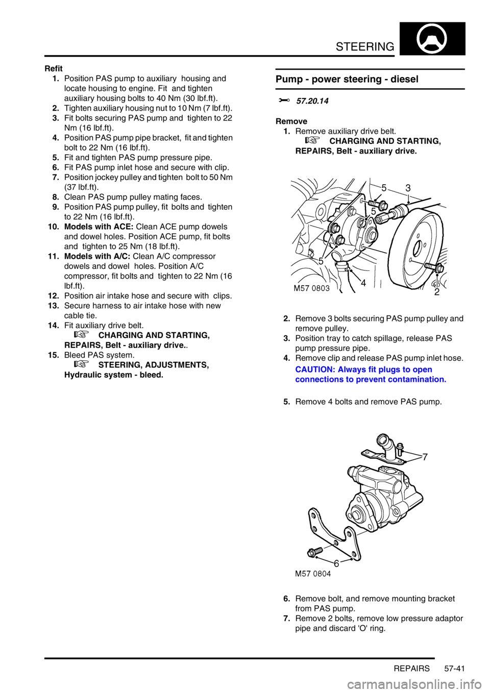
2.Remove 3 bolts securing PAS pump pulley and
remove pulley.
3.Position tray to catch spillage, release PAS
pump pressure pipe.
4.Remove clip and release PAS pump inlet hose.
CAUTION: Always fit plugs to open
connections to prevent contamination.
5.Remove 4 bolts and remove PAS pump.
6.Remove bolt, and remove mounting bracket
from PAS pump.
7.Remove 2 bolts, remove low pressure adaptor
pipe and discard 'O' ring.
Page 931 of 1672

STEERING
57-44 REPAIRS
14.Position steering column assembly in a vice.
15.Remove 2 screws and remove ignition switch.
16.Remove cable tie and remove multiplug from
ignition switch.
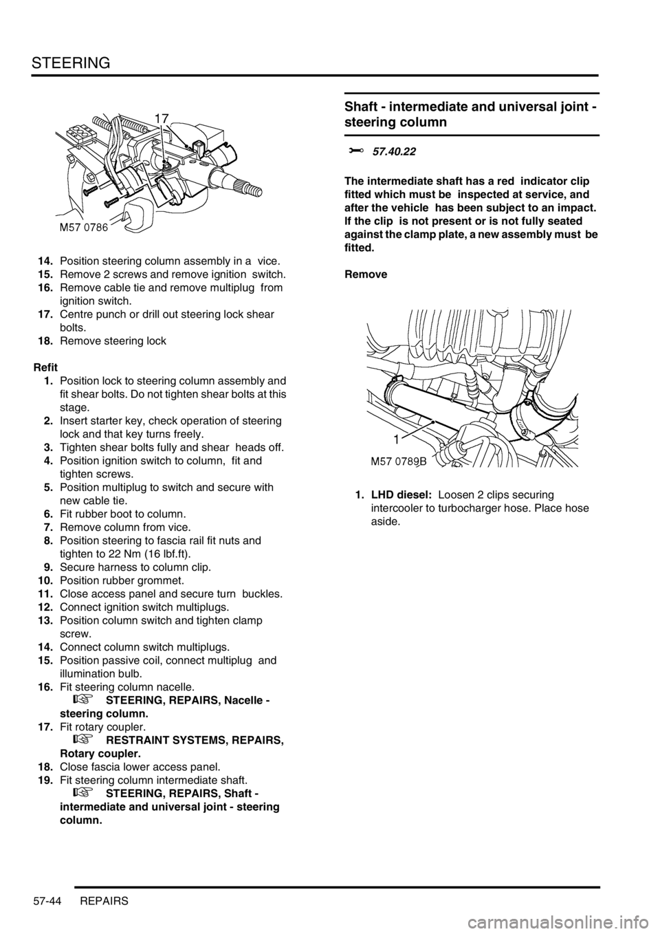
17.Centre punch or drill out steering lock shear
bolts.
18.Remove steering lock
Refit
1.Position lock to steering column assembly and
fit shear bolts. Do not tighten shear bolts at this
stage.
2.Insert starter key, check operation of steering
lock and that key turns freely.
3.Tighten shear bolts fully and shear heads off.
4.Position ignition switch to column, fit and
tighten screws.
5.Position multiplug to switch and secure with
new cable tie.
6.Fit rubber boot to column.
7.Remove column from vice.
8.Position steering to fascia rail fit nuts and
tighten to 22 Nm (16 lbf.ft).
9.Secure harness to column clip.
10.Position rubber grommet.
11.Close access panel and secure turn buckles.
12.Connect ignition switch multiplugs.
13.Position column switch and tighten clamp
screw.
14.Connect column switch multiplugs.
15.Position passive coil, connect multiplug and
illumination bulb.
16.Fit steering column nacelle.
+ STEERING, REPAIRS, Nacelle -
steering column.
17.Fit rotary coupler.
+ RESTRAINT SYSTEMS, REPAIRS,
Rotary coupler.
18.Close fascia lower access panel.
19.Fit steering column intermediate shaft.
+ STEERING, REPAIRS, Shaft -
intermediate and universal joint - steering
column.
Shaft - intermediate and universal joint -
steering column
$% 57.40.22
The intermediate shaft has a red indicator clip
fitted which must be inspected at service, and
after the vehicle has been subject to an impact.
If the clip is not present or is not fully seated
against the clamp plate, a new assembly must be
fitted.
Remove
1. LHD diesel: Loosen 2 clips securing
intercooler to turbocharger hose. Place hose
aside.
Page 932 of 1672

STEERING
REPAIRS 57-45
2.Remove bolt securing intermediate shaft to
steering column.
3.Remove bolt securing intermediate shaft to
universal joint.
4. Universal joint: Remove the bolt securing the
universal joint to the steering box.5.Ensure steering wheel is in the straight ahead
position and fit centralising bolt to steering box.
Remove the key from the ignition switch
CAUTION: Do not turn the steering wheel
with the intermediate shaft or universal joint
disconnected as damage to the rotary
coupler and the steering wheel switches
may occur.
Page 933 of 1672

STEERING
57-46 REPAIRS
6. Intermediate shaft: Slide the intermediate
shaft upwards, release from the universal joint
and remove intermediate shaft from the
steering column.
7. Universal joint: Slide the intermediate shaft
upwards, release from the universal joint and
remove universal joint from the steering box. Refit
1.Clean and inspect splines for wear and
damage.
2. Intermediate shaft: Locate intermediate shaft
on steering column and engage with universal
joint. Ensure splines are fully engaged and bolt
holes aligned.
3. Universal joint: Locate universal joint on
steering box and engage in intermediate shaft.
Ensure splines are fully engaged and bolt
holes aligned.
4.Fit bolts securing intermediate shaft to
universal joint and tighten to 25 Nm (18 lbf.ft).
5. Intermediate shaft: Fit bolts securing
intermediate shaft to steering column and
tighten to 25 Nm (18 lbf.ft).
6. Universal joint: Fit bolts securing universal
joint to steering box and tighten to 25 Nm (18
lbf.ft).
7. LHD diesel: Connect hose to turbocharger
and intercooler and secure the clips.
8.Fit ignition key, remove steering box
centralising bolt and check that steering wheel
is in the straight ahead position.
Page 1026 of 1672

REAR SUSPENSION
DESCRIPTION AND OPERATION 64-21
Normal ride height
When the vehicle is stationary, a door is open and the ignition is off, the SLS system will allow the rear of the vehicle
to lower to within 20 mm of the normal ride height as load is removed from the vehicle. The SLS system will only
operate the compressor to raise the rear of the vehicle when the engine is running, unless requested using the remote
handset.
Off-road mode (ORM)
ORM is used to raise the rear of the vehicle from normal ride height to the ORM ride height of 100 mm between the
tip of the bump stop and the axle.
ORM is activated by depressing the ORM switch located on the fascia for not less than 0.5 seconds. With the engine
running, all doors closed and the vehicle speed below 18 mph (30 km/h), the audible warning will sound once and the
ORM warning lamp in the instrument pack will start to flash when the switch is released. The compressor will be
started and the air control valves will be energised by the ECU to inflate the air springs and raise the rear of the vehicle.
When the full ORM height is reached, the ECU will terminate compressor operation and close the air valves. The ORM
warning lamp will stop flashing and remain continuously illuminated to inform the driver that the SLS system is in ORM.
When ORM is no longer required, depressing the ORM switch for not less than 0.5 seconds with all doors closed will
lower the SLS to normal ride height. The audible warning will sound once and the ORM warning lamp will flash as the
suspension lowers. The ECU energises the air control valves and the exhaust valve to release air pressure from the
air springs. When standard ride height is reached the ORM warning lamp will extinguish and the ECU will de-energise
the air control valves and the exhaust valve solenoids.
If the SLS is in ORM and the vehicle speed exceeds 18 mph (30 km/h), the ECU will lower the SLS to standard ride
height. The driver will be informed of this by an audible warning and the ORM warning lamp flashing as the suspension
lowers. When normal ride height is achieved, the ORM warning lamp will extinguish.
At sea level, the time to change the SLS from normal ride height to ORM or visa versa will take between 15 and 20
seconds.
If the ECU determines that conditions are not correct for SLS operation, i.e.; axle articulation or system fault, the
audible warning will sound three times to inform the driver that the ORM request has not been granted.
Extended mode
The extended mode is automatically operated by the ECU and requires no input from the driver. Extended mode
operates when the chassis is grounded causing the rear wheels to spin. This information is generated by the ABS
function of the SLABS ECU.
When the ECU senses that the chassis is grounded and the vehicle speed is less than 6 mph (10 km/h), the ECU will
operate the compressor and energise the air control valves for 25 seconds to raise the rear of the vehicle. This
operates irrespective of the mode that the SLS system is in at that time. To inform the driver, the ORM warning lamp
will flash continuously at all times that the system is in extended mode.
The driver can exit the extended mode by depressing the ORM switch for not less than 0.5 seconds or by exceeding
8 mph (13 km/h).
Remote handset SLS control
The remote handset is an accessory item which allows the SLS to be operated between normal ride height and bump
stop height to allow easier connection and disconnection of trailers. The remote handset is similar in appearance to
that of the remote door locking handset but does not have an integral key. A circular button with an arrow is used to
raise the SLS and an oval button with the 'Land Rover' logo is used to lower the SLS.
The remote handset control requires all doors to be closed and the ignition to be in position II, but the engine does
not need to be running.
Page 1071 of 1672

BRAKES
70-26 DESCRIPTION AND OPERATION
Description
General
The handbrake consists of a drum brake, installed on the rear of the transfer box, operated by a cable connected to
a handbrake lever between the front seats.
Handbrake lever
The handbrake lever is mounted on a base plate which attaches to the transmission tunnel. A conventional ratchet
and thumb operated release button are incorporated for locking and unlocking the lever. A warning switch on the base
of the lever operates the brake warning lamp in the instrument pack. While the handbrake is applied the warning
switch connects an earth to the instrument pack which, if the ignition is on, illuminates the brake warning lamp. In
some markets, the instrument pack performs a bulb check of the brake warning lamp each time the ignition is switched
on.
Cable
The handbrake cable consists of inner and outer cables installed between the handbrake lever and the drum brake.
A protective sleeve is installed on the cable to protect the cable from heat from the exhaust system. Handbrake
adjustment is provided by a threaded sleeve installed on the outer cable where it locates in the handbrake lever.
Turning an adjuster wheel, which is keyed to the threaded sleeve and secured by a 'C' clip, alters the effective length
of the outer sleeve and consequently changes the handbrake lever movement needed to apply the drum brake.
Page 1113 of 1672

RESTRAINT SYSTEMS
75-18 REPAIRS
Pre-tensioner - front seat belt
$% 76.73.30
WARNING: It is imperative that before any work
is undertaken on the SRS system the appropriate
information is read thoroughly.
WARNING: Always disconnect both battery leads
before beginning work on the SRS system.
Disconnect the negative battery lead first. Never
reverse connect the battery.
Remove
1.Remove the key from the starter switch.
Disconnect both battery leads, negative lead
first. Wait ten minutes before starting work.
2.Remove front seat.
+ SEATS, REPAIRS, Seat - front.
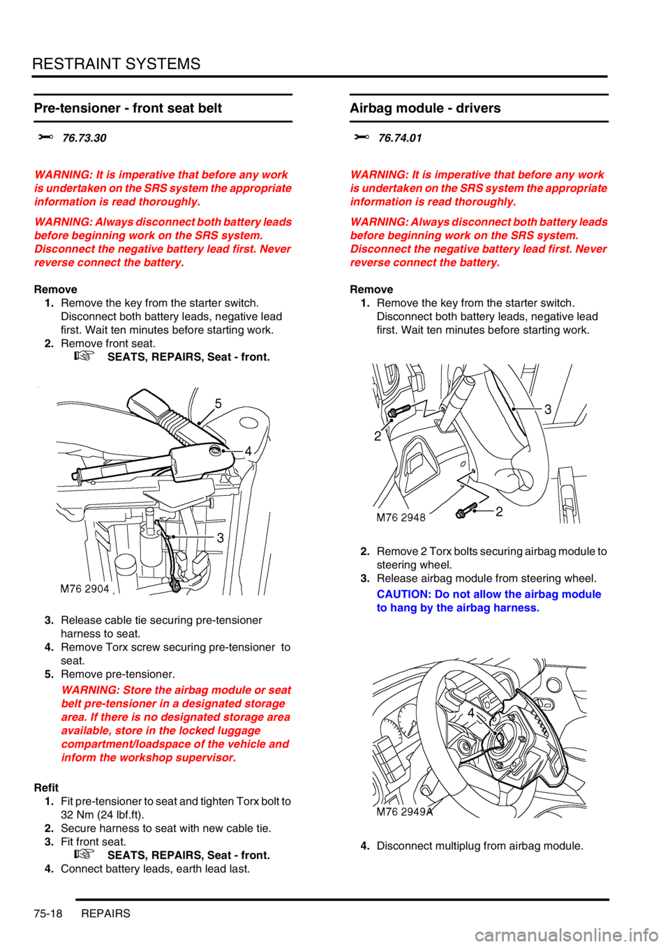
3.Release cable tie securing pre-tensioner
harness to seat.
4.Remove Torx screw securing pre-tensioner to
seat.
5.Remove pre-tensioner.
WARNING: Store the airbag module or seat
belt pre-tensioner in a designated storage
area. If there is no designated storage area
available, store in the locked luggage
compartment/loadspace of the vehicle and
inform the workshop supervisor.
Refit
1.Fit pre-tensioner to seat and tighten Torx bolt to
32 Nm (24 lbf.ft).
2.Secure harness to seat with new cable tie.
3.Fit front seat.
+ SEATS, REPAIRS, Seat - front.
4.Connect battery leads, earth lead last.
Airbag module - drivers
$% 76.74.01
WARNING: It is imperative that before any work
is undertaken on the SRS system the appropriate
information is read thoroughly.
WARNING: Always disconnect both battery leads
before beginning work on the SRS system.
Disconnect the negative battery lead first. Never
reverse connect the battery.
Remove
1.Remove the key from the starter switch.
Disconnect both battery leads, negative lead
first. Wait ten minutes before starting work.
2.Remove 2 Torx bolts securing airbag module to
steering wheel.
3.Release airbag module from steering wheel.
CAUTION: Do not allow the airbag module
to hang by the airbag harness.
4.Disconnect multiplug from airbag module.
Page 1114 of 1672

RESTRAINT SYSTEMS
REPAIRS 75-19
5.Remove airbag module.
WARNING: Store the airbag module with the
deployment side uppermost. If it is stored
deployment side down, accidental
deployment will propel the airbag module
with enough force to cause serious injury.
WARNING: Store the airbag module or seat
belt pre-tensioner in a designated storage
area. If there is no designated storage area
available, store in the locked luggage
compartment/loadspace of the vehicle and
inform the workshop supervisor.
Refit
NOTE: If the airbag module is to be replaced,
the bar code of the new module must be
recorded.
1.Position airbag module and connect multiplug.
2.Fit airbag module to steering wheel and tighten
Torx bolts to 9 Nm (7 lbf.ft).
3.Connect battery leads, earth lead last.
Airbag module - passenger
$% 76.74.02
WARNING: It is imperative that before any work
is undertaken on the SRS system the appropriate
information is read thoroughly.
WARNING: Always disconnect both battery leads
before beginning work on the SRS system.
Disconnect the negative battery lead first. Never
reverse connect the battery.
Remove
1.Remove the key from the starter switch.
Disconnect both battery leads, negative lead
first. Wait ten minutes before starting work.
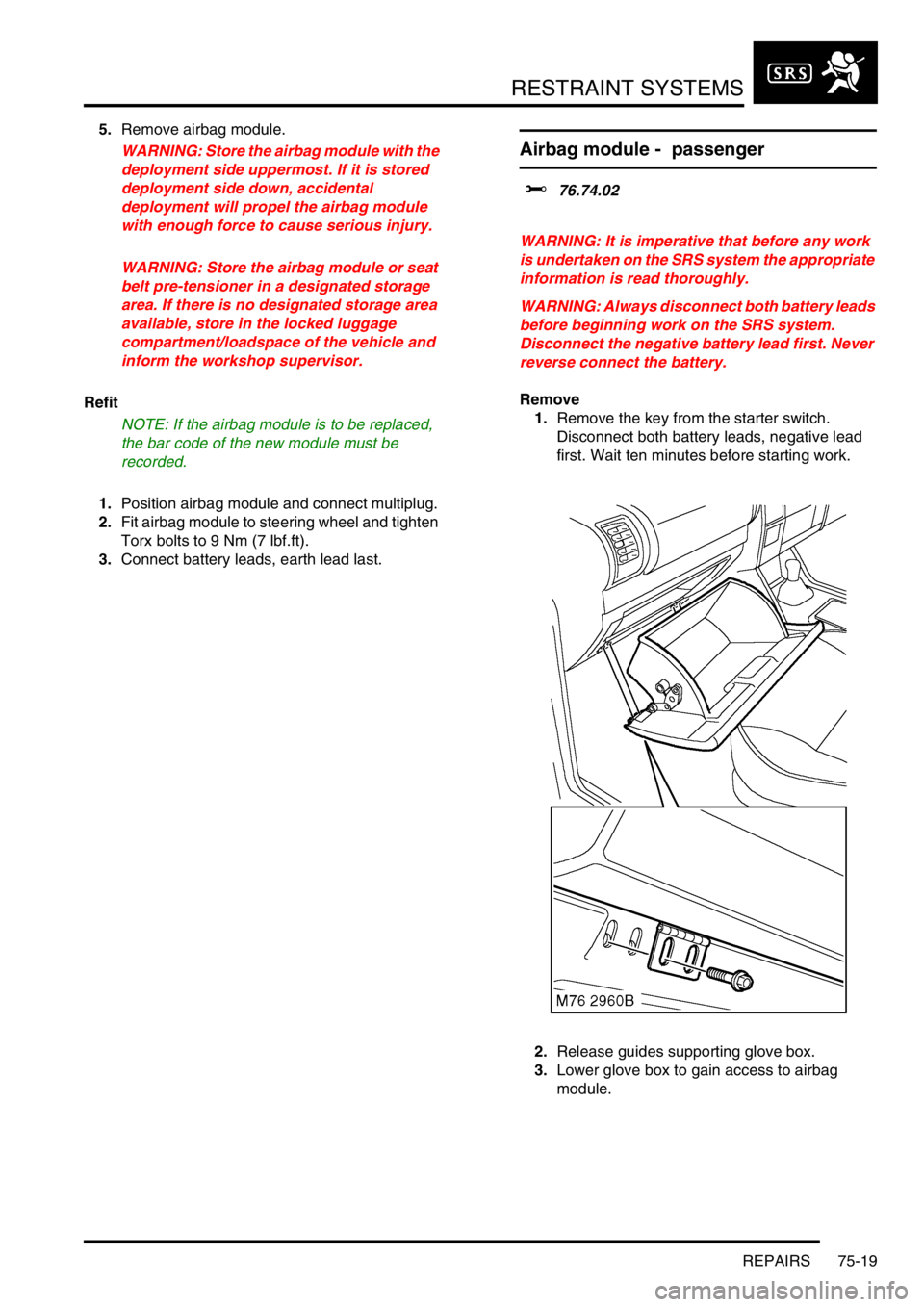
2.Release guides supporting glove box.
3.Lower glove box to gain access to airbag
module.