2002 LAND ROVER DISCOVERY key
[x] Cancel search: keyPage 1532 of 1672

ALARM SYSTEM AND HORN
DESCRIPTION AND OPERATION 86-4-23
Depending on which market the vehicle is sold, either the vehicle horn, a specific alarm sounder, or a BBUS operates
in phase with the direction indicators when the alarm is triggered. The audible warning device operates for
approximately 30 seconds at 0.25 second on, and 0.25 second off. The BCU allows the alarm to be triggered up to 3
times in any armed period.
Theft deterrent LED
An LED located in the instrument pack indicates the status of the alarm system.
There are eight theft deterrent alarm configurations:
lNo handset low battery warning.
lHandset low battery warning.
lNo passive immobilisation.
lPassive immobilisation.
lEngine immobilised (ignition off, LED off).
lEngine immobilised (ignition off, LED flashes).
lNo alarm tampered indication.
lAlarm tampered indication.
The theft deterrent LED utilises a particular flash to show the status of the following:
lAlarm armed.
lEngine immobilised.
lAlarm tampered.
lHandset low battery warning.
Transit mode
To prevent excessive battery drain during transportation to overseas markets, the vehicle is placed in a transit mode
at the end of line test.
The following functions are disabled when the vehicle is in transit mode:
lVolumetric sensors.
lPassive immobilisation.
lMobilisation of the vehicle by use of door lock.
lIgnition key interlock.
lElectric seat enable time-out with drivers door open.
To exit this mode, switch on the ignition and simultaneously hold down the heated rear window and the rear fog lamp
switch for 2 seconds.
Transit mode can be entered using Testbook.
Page 1568 of 1672

IN CAR ENTERTAINMENT
REPAIRS 86-6-15
Switches - remote control - ICE
$% 86.50.13
Remove
1.Remove the key from the starter switch.
Disconnect both battery leads, negative lead
first. Wait ten minutes before starting work.
2.Remove driver's airbag module.
+ RESTRAINT SYSTEMS, REPAIRS,
Airbag module - drivers.
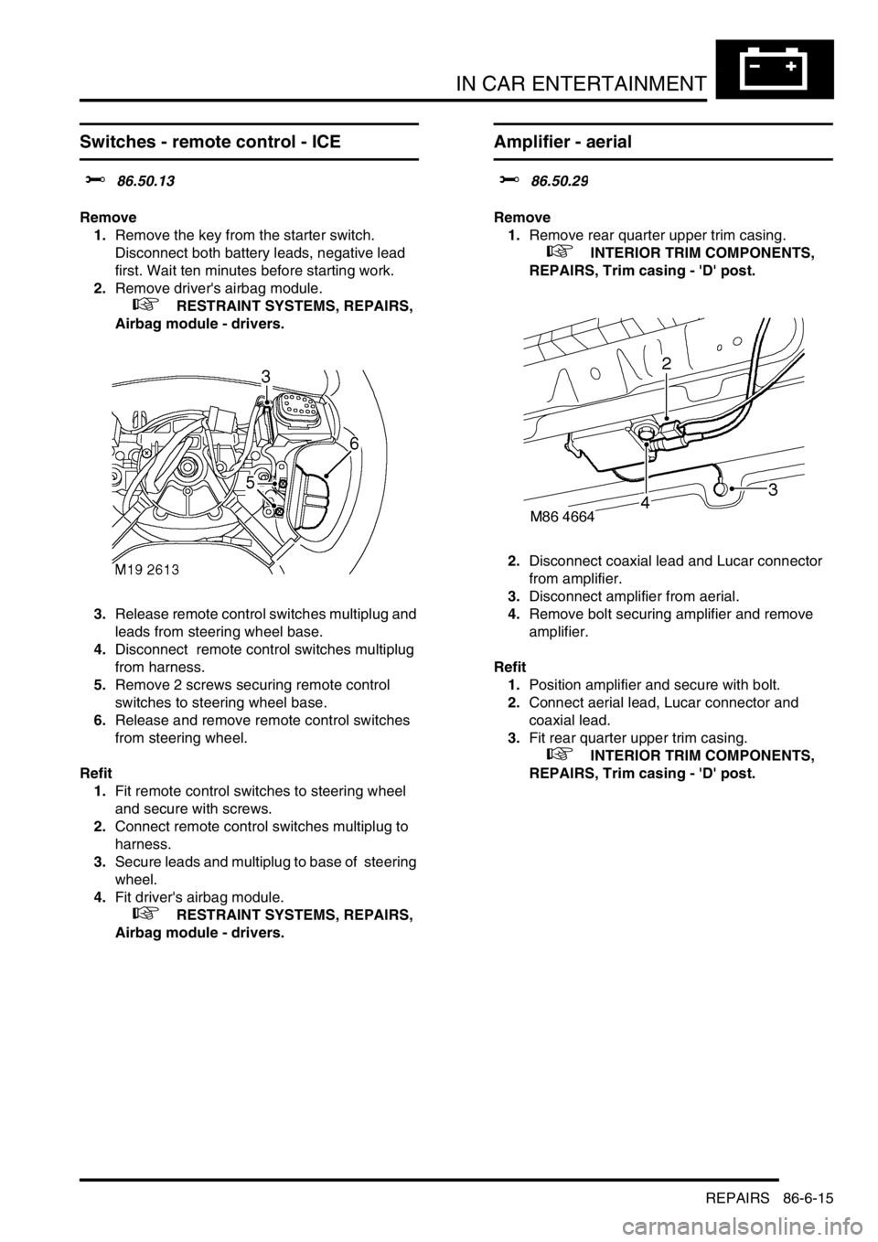
3.Release remote control switches multiplug and
leads from steering wheel base.
4.Disconnect remote control switches multiplug
from harness.
5.Remove 2 screws securing remote control
switches to steering wheel base.
6.Release and remove remote control switches
from steering wheel.
Refit
1.Fit remote control switches to steering wheel
and secure with screws.
2.Connect remote control switches multiplug to
harness.
3.Secure leads and multiplug to base of steering
wheel.
4.Fit driver's airbag module.
+ RESTRAINT SYSTEMS, REPAIRS,
Airbag module - drivers.
Amplifier - aerial
$% 86.50.29
Remove
1.Remove rear quarter upper trim casing.
+ INTERIOR TRIM COMPONENTS,
REPAIRS, Trim casing - 'D' post.
2.Disconnect coaxial lead and Lucar connector
from amplifier.
3.Disconnect amplifier from aerial.
4.Remove bolt securing amplifier and remove
amplifier.
Refit
1.Position amplifier and secure with bolt.
2.Connect aerial lead, Lucar connector and
coaxial lead.
3.Fit rear quarter upper trim casing.
+ INTERIOR TRIM COMPONENTS,
REPAIRS, Trim casing - 'D' post.
Page 1622 of 1672

NAVIGATION SYSTEM
DESCRIPTION AND OPERATION 87-7
Sensor Check
1Call up the SENSORS screen on the LCD:
lIf the navigation CD-ROM has not been installed before, press and hold multifunction button 1 then press
multifunction button 10.
lIf the navigation CD-ROM has been installed before, use the garage menu as detailed above.
2Drive the vehicle forwards a short distance at a speed greater than 2.5 mph (4 km/h) and ensure the road speed
counter on the SENSORS screen starts to increment.
3Select reverse gear and ensure the direction arrows on the SENSORS screen point rearwards.
4Ensure the GPS data on the SENSORS screen is displayed and updated.
NOTE: The GPS data will randomly display a GPS MODULE FAILURE message. This is not a fault condition, and
no action need be taken, provided the GPS data switches between the GPS MODULE FAILURE message and
actual GPS data.
5Exit the SENSORS screen:
lIf the navigation CD-ROM has not been installed before, press and hold multifunction button 1 then press
multifunction button 10.
lIf the navigation CD-ROM has been installed before, press the Nav button.
Calibration Routine
1Park the vehicle outside in an area clear of high buildings, trees etc.
NOTE: The more open the surrounding area is, the faster the system will acquire sufficient GPS satellite signals to
begin calibration. To minimise the calibration time, the vehicle should not be moved again until the calibration
ride.
2Turn the ignition switch to position II. If the navigation computer does not come on, press the navigation
computer ON button.
3If necessary, use the navigation computer multifunction buttons to enter the security code.
4Turn the ignition switch to position 0 and remove the ignition key.
5Press the navigation computer ON button.
6Call up the SENSORS screen on the LCD:
lIf the navigation CD-ROM has not been installed before, press and hold multifunction button 1 then press
multifunction button 10.
lIf the navigation CD-ROM has been installed before, use the garage menu as detailed above.
7Turn the LH rotary control to minimum volume.
8Wait for 30 minutes. If necessary, the vehicle can be left unattended and locked.
NOTE: Land Rover recommend a minimum of 30 minutes be allowed to elapse in order to ensure that only a short
distance need be driven to achieve calibration.
9After the 30 minutes have elapsed, ensure the navigation computer LCD shows a GPS almanac figure of 27 or
higher.
10Start the vehicle engine and allow to idle.
11Install the navigation CD-ROM.
12Wait until the navigation computer LCD prompts for a language to be selected. Turn the RH rotary control to
scroll through the options, highlight the required language and press the RH rotary control to select.
13The navigation computer LCD will prompt for a voice to be selected. Turn the RH rotary control to scroll through
the options, highlight the required voice and press the RH rotary control to select.
14Wait until the navigation computer LCD advises "language has been loaded OK". Press the RH rotary control to
confirm the language and voice selections.
15The navigation computer LCD will default to the CALIBRATION RIDE screen and should show the
CALIBRATION RIDE CAN START message. The GPS data and the road speed counter will also be shown.
16Drive the vehicle over a road route approximating that shown below (it is not necessary to copy the route
exactly). Calibration is complete when the navigation computer LCD switches to show DESTINATION & POI
and the satellite graphic. If all the pre calibration ride conditions were complied with, calibration is typically
achieved within 3 miles (5 km) and usually occurs when the vehicle returns to the start point. However,
calibration may be achieved earlier in the journey and, if it is, there is no need to complete the remainder of the
calibration route.
Page 1627 of 1672

NAVIGATION SYSTEM
87-12 REPAIRS
Display unit
$% 86.53.20
Remove
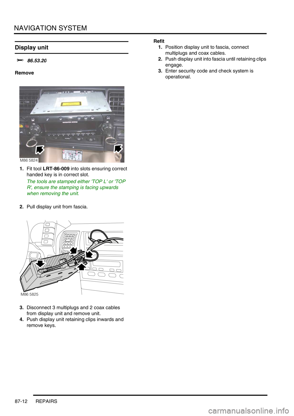
1.Fit tool LRT-86-009 into slots ensuring correct
handed key is in correct slot.
The tools are stamped either 'TOP L' or 'TOP
R', ensure the stamping is facing upwards
when removing the unit.
2.Pull display unit from fascia.
3.Disconnect 3 multiplugs and 2 coax cables
from display unit and remove unit.
4.Push display unit retaining clips inwards and
remove keys.Refit
1.Position display unit to fascia, connect
multiplugs and coax cables.
2.Push display unit into fascia until retaining clips
engage.
3.Enter security code and check system is
operational.
M86 5824
M86 5825
Page 1667 of 1672

INSTRUMENTS
88-40 DESCRIPTION AND OPERATION
Audible warning speaker
The audible warning speaker is integral with the instrument pack and provides an audible warning to alert the driver
of the following situations:
lSeat belt warning lamp.
lKey in/lights on warning.
lSLABS command received warning.
lTransfer box in neutral warning.
lLights on warning.
It has a maximum pressure level of 87 dB at 1 metre (3.3 ft). The audible warning speaker is located on the rear of
the instrument pack.
The power input for the audible warning speaker is supplied by the instrument pack via fuse 27.
The BCU provides the earth paths for the following:
lThe seatbelt warning.
lKey in/lights on warning.
lLights on warning.
The SLABS ECU provides the earth paths for the SLABS commands. The EAT ECU provides the earth path for the
transfer box in neutral warning.
The BCU activates the audible warning speaker to produce audible warnings.
The audible warning speaker can operate with the ignition off.
The seatbelt warning will commence at key on, and in the event of a serial link failure, will terminate after 6 seconds.
The SLABS warnings are sounded only once for each received command.
The lights on warning and transfer box in neutral are sounded continuously until a sound off command is received.
Sound request number Sound functions Priority (1 = lowest, 6 = highest)
0Off 1
1 Seat belt warning 6
2 Key-in warning 3
3 SLABS/ HDC warning 4
4 Transfer box in neutral warning 5
5 Lights on warning 2